Crankshaft and Bearing Installation
|
|
Crankshaft and Bearing Installation
|
|
Note
|
|
If crankshaft bearing failure is due to other than normal wear, investigate the cause. Inspect the crankshaft or connecting rod bearing bores.
|
Inspect the connecting rod bearing bores or crankshaft main bearing bores using the following procedure:
|
•
|
Tighten the bedplate to specification using the
EN-45059
angle meter .
|
|
•
|
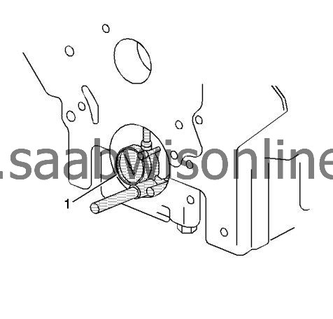
Measure the bearing bore for taper and out-of-round using the
EN-8087
gauge (1).
|
|
•
|
No taper or out-of-round should exist.
|
Measure the bearing clearance to determine the correct replacement bearing insert size. There are 2 methods to measure bearing clearance. Method A gives more reliable results and is preferred.
|
•
|
Method A yields measurement from which the bearing clearance can be computed.
|
|
•
|
Method B yields the bearing clearance directly. Method B does not give any indication of bearing run-out.
|
|
Note
|
|
Do not mix inserts of different nominal size in the same bearing bore.
|
To measure bearing clearance using Method A, use the following procedure:
|
1.
|
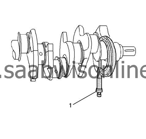
Measure the crankshaft bearing journal diameter with a micrometer (1) in several places, 90 degrees apart. Average the measurements.
|
|
2.
|
Measure the crankshaft bearing journal taper and runout.
|
|
3.
|
Install the lower crankcase and tighten the bearing cap bolts to specification.
|
|
4.
|
Measure bearing inside diameter (ID) in several places 90 degrees apart, average measurements.
|
|
5.
|
Subtract journal measurement from bearing ID measurement to determine clearance.
|
|
6.
|
Determine whether clearance is within specification.
|
|
7.
|
If out of specification, choose different inserts.
|
|
8.
|
Measure the connecting rod inside diameter in the same direction as the length of the rod with an inside micrometer.
|
|
9.
|
Measure the crankshaft main bearing inside diameter with an inside micrometer.
|
To measure bearing clearance using Method B, use the following procedure:
|
1.
|
Clean the used bearing inserts.
|
|
2.
|
Install the used bearing inserts.
|
|
3.
|
Place a piece of gaging plastic across the entire bearing width.
|
|
4.
|
Install the bearing caps.
|
|
5.
|
 Warning
|
|
In order to prevent the possibility of cylinder block or crankshaft bearing cap damage, the crankshaft bearing caps are tapped into the cylinder block cavity using a brass, lead, or a leather mallet before the attaching bolts are installed. Do not use attaching bolts to pull the crankshaft bearing caps into the seats. Failure to use this process may damage a cylinder block or a bearing cap.
|
|
|
|
|
|
Install the bearing cap bolts to specification.
|
|
6.
|
|
Note
|
|
Do not rotate the crankshaft.
|
Remove the bearing cap, leaving the gaging plastic in place. It does not matter whether the gaging plastic adheres to the journal or to the bearing cap.
|
|
7.
|
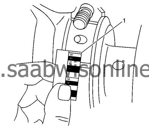
Measure the gaging plastic at its widest point with the scale (1) printed on the gaging plastic package.
|
|
8.
|
Remove the gaging plastic.
|