PRE-RELEASE
Cylinder Head Replacement
| Cylinder Head Replacement |
Special Tools
| • |
EN-38188
Cylinder Head Broken Bolt Extractor Kit
|
|
| • |
EN-45059
Angle Meter
|
|
For equivalent regional tools, refer to Special Tools (LDK, LHU) .
| Removal Procedure |
| 1. |
Disconnect the negative battery cable. Refer to
Battery Negative Cable Disconnection and Connection
.
|
|
| 2. |
Drain the cooling system. Refer to
Cooling System Draining and Filling (LDK/A20NHT)
and
Cooling System Draining and Filling (LBS/A20DTH)
Cooling System Draining and Filling (LAU/A28NER)
.
|
|
| 3. |
Remove the camshaft position actuator solenoid valve - intake. Refer to
Camshaft Position Actuator Solenoid Valve Replacement (Exhaust)
Camshaft Position Actuator Solenoid Valve Replacement (Intake)
.
|
|
| 4. |
Remove the camshaft position actuator solenoid valve - exhaust. Refer to
Camshaft Position Actuator Solenoid Valve Replacement (Exhaust)
Camshaft Position Actuator Solenoid Valve Replacement (Intake)
.
|
|
| 5. |
Remove the intake manifold. Refer to
Intake Manifold Replacement
.
|
|
| 6. |
Remove the exhaust manifold. Refer to
Exhaust Manifold Replacement (Diesel)
Exhaust Manifold Replacement (LDK/A20NHT)
.
|
|
| 7. |
Remove the timing chain guide - upper. Refer to
Timing Chain Guide Replacement - Upper
.
|
|
| 8. |
Remove the hydraulic valve lash adjuster - exhaust. Refer to
Hydraulic Valve Lash Adjuster Replacement - Exhaust
.
|
|
| 9. |
Remove the hydraulic valve lash adjuster - intake. Refer to
Hydraulic Valve Lash Adjuster Replacement - Intake
.
|
|
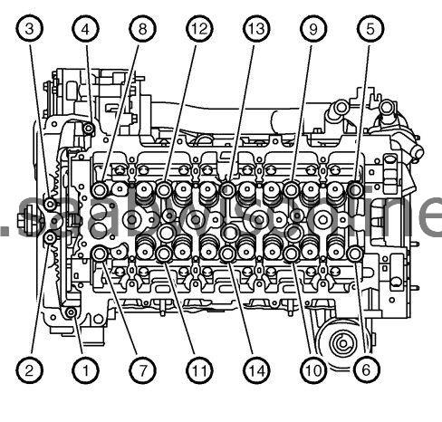
| 10. |
Remove the cylinder head to the block fastener in sequence.
|
|
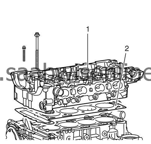
| 11. |
Remove the cylinder head (1) and the cylinder head gasket (2) from the block.
|
|
| 12. |
Clean all of the gasket surfaces.
|
|
| • |
Use a razor blade gasket scraper to clean the cylinder head and cylinder block gasket surfaces. Do not scratch or gouge any surfaces.
|
| • |
Use a new blade for each cylinder head and cylinder block. |
|||||||
| • |
Hold the razor blade (1) as parallel to the gasket surfaces (2) as possible. 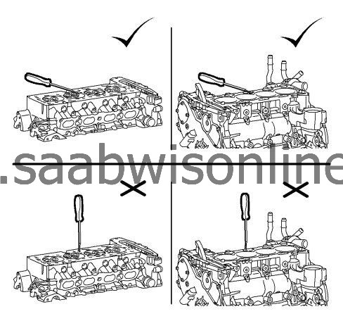
|
|||||||
| 13. |
Clean the fastener holes with a nylon bristle brush. |
|||||||
| 14. |
When cleaning the cylinder head bolt holes, use a suitable solvent in spray form. Use a compressed-air cleaning pistol with an extra long nozzle to reach the bottom of the holes. |
|||||||||
 Warning
| 15. |
Remove any broken long cylinder head fastener using the
EN-38188
cylinder head broken bolt extractor kit .
|
|
| Installation Procedure |
| 1. |
Install the cylinder head gasket (1) to the cylinder block (2). On right ones sit pay attention from the cylinder head lock pin (3). 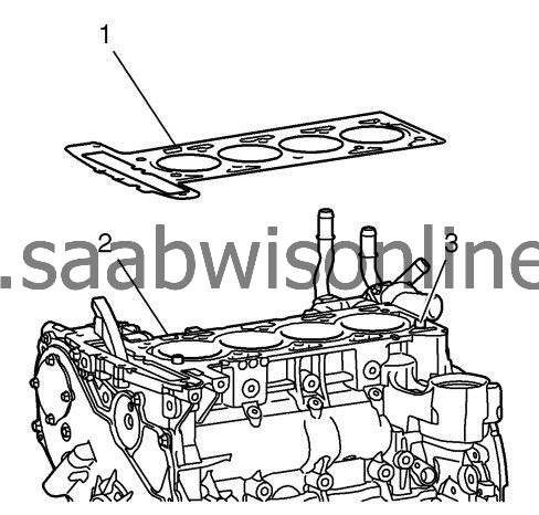
|
|||||||
| 2. |
Ensure the number 1 cylinder is at top dead center (TDC).
Setting up the crankshaft balancer mark (1) to the oil pump housing mark (2). 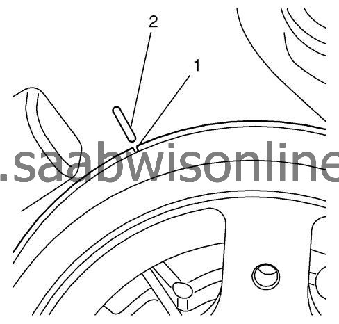
|
|
| 3. |
Refer to
Fastener Caution
.
Install the cylinder head. 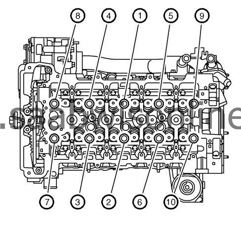
|
|||||||
| 4. |
Install NEW cylinder head fastener.
|
|
| • |
Tighten the fasteners in sequence to
30 Nm (22 lb ft)
.
|
| • |
Tighten the fastener in additional
155
degrees in sequence using the
EN-45059
angle meter .
|
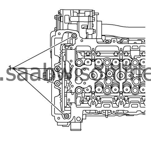
| 5. |
Install the front cylinder head fastener (1) and tighten to
35 Nm (26 lb ft)
.
|
|
| 6. |
Install the hydraulic valve lash adjuster - intake. Refer to
Hydraulic Valve Lash Adjuster Replacement - Intake
.
|
|
| 7. |
Install the hydraulic valve lash adjuster - exhaust. Refer to
Hydraulic Valve Lash Adjuster Replacement - Exhaust
.
|
|
| 8. |
Install the timing chain guide - upper. Refer to
Timing Chain Guide Replacement - Upper
.
|
|
| 9. |
Install the exhaust manifold. Refer to
Exhaust Manifold Replacement (Diesel)
Exhaust Manifold Replacement (LDK/A20NHT)
.
|
|
| 10. |
Install the intake manifold. Refer to
Intake Manifold Replacement
.
|
|
| 11. |
Install the camshaft position actuator solenoid valve - exhaust. Refer to
Camshaft Position Actuator Solenoid Valve Replacement (Exhaust)
Camshaft Position Actuator Solenoid Valve Replacement (Intake)
.
|
|
| 12. |
Install the camshaft position actuator solenoid valve - intake. Refer to
Camshaft Position Actuator Solenoid Valve Replacement (Exhaust)
Camshaft Position Actuator Solenoid Valve Replacement (Intake)
.
|
|
| 13. |
Fill the cooling system. Refer to
Cooling System Draining and Filling (LDK/A20NHT)
and
Cooling System Draining and Filling (LBS/A20DTH)
Cooling System Draining and Filling (LAU/A28NER)
.
|
|
| 14. |
Connect the negative battery cable. Refer to
Battery Negative Cable Disconnection and Connection
.
|
|
