PRE-RELEASE
Intake Manifold Installation (LDK, LHU)
| Intake Manifold Installation (LDK, LHU) |
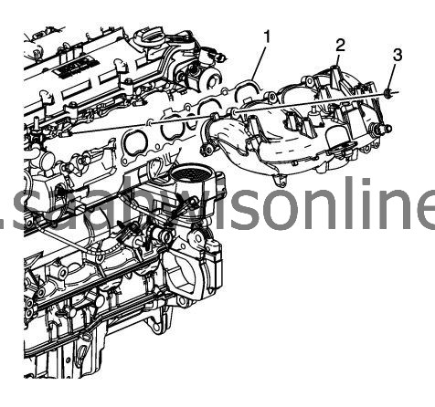
| 1. |
Install a NEW intake manifold gasket (1).
|
|
| 2. |
Install the intake manifold (2).
|
|
| 3. |
Refer to
Fastener Caution
.
Install the intake manifold bolts and nuts (3) finger tight. |
|
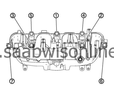
| 4. |
Tighten the intake manifold bolts and nuts in sequence:
|
|
| 4.1. |
Tighten the intake manifold bolts to
25 Nm (18 lb ft)
.
|
| 4.2. |
Tighten the intake manifold nuts to
22 Nm (16 lb ft)
.
|
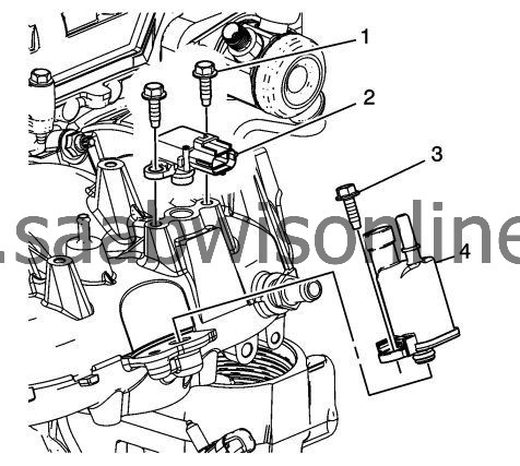
| 5. |
Install the EVAP purge solenoid valve (4) and bolt (3). Tighten the bolt to
4 Nm (35 lb in)
.
|
|
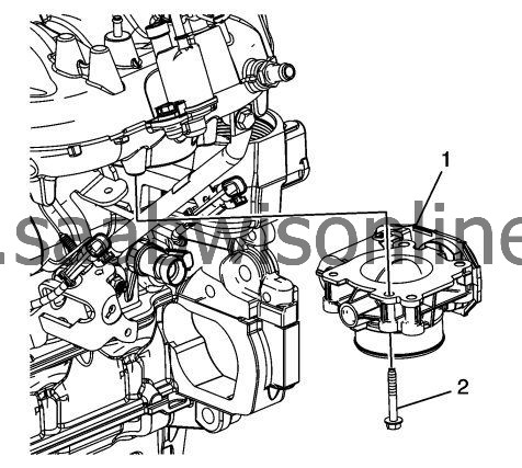
| 6. |
Install the MAP sensor (2) and bolt (1). Tighten the bolt to
4 Nm (35 lb in)
.
|
|
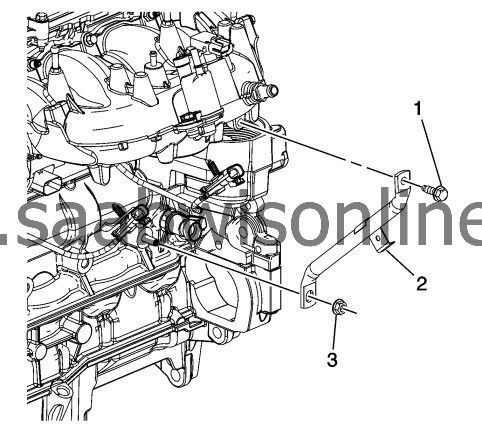
| 7. |
Install the intake manifold brace (2).
|
|
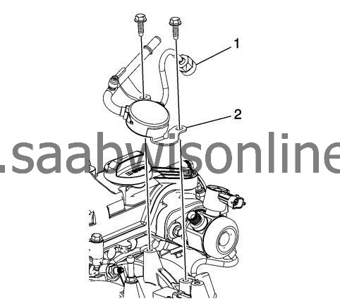
| 8. |
Install the intake manifold brace bolt (1) and nut (3) and tighten to
25 Nm (18 lb ft)
.
|
|
| 9. |
Connect the rear knock sensor to the intake manifold brace.
|
|
| 10. |
Install the throttle body (1).
|
|
| 11. |
Install the throttle body bolts (2) and tighten to
10 Nm (89 lb in)
.
|
|
| 12. |
Lubricate the high pressure fuel pump fuel feed line connection threads with clean 5W30 engine oil.
|
|
| 13. |
Install the fuel feed line. (2)
|
|
| 14. |
Install the fuel feed line bolts.
|
|
| 15. |
Connect the low pressure fuel line nut (1) and tighten to
30 Nm (22 lb ft)
.
|
|
| 16. |
Tighten the fuel line bolts to
10 Nm (89 lb in)
.
|
|
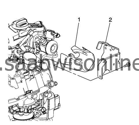
| 17. |
Install the high pressure fuel pump noise insulator (1).
|
|
| 18. |
Install the high pressure fuel pump cover (2).
|
|
| 19. |
Install the HP fuel pump cover bolts and tighten to
10 Nm (89 lb in)
.
|
|
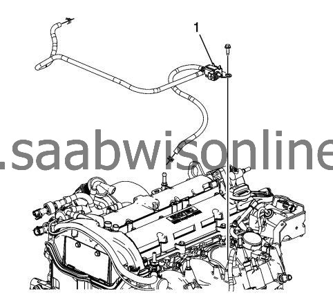
| 20. |
Install the charger AIR bypass valve solenoid (1) with charger AIR bypass tube assemblies.
|
|
| 21. |
Install the charger (AIR) bypass valve solenoid bolts and tighten to
10 Nm (89 lb in)
.
|
|
| 22. |
Connect the charger AIR bypass tube assemblies and clips from the charger AIR bypass valve solenoid to the turbocharger and vehicle. |
|||||||
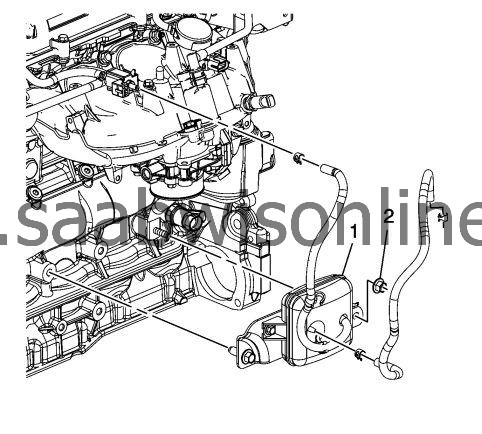
| 23. |
Install the charger AIR bypass valve tank assembly (1).
|
|
| 24. |
Tighten the charger AIR bypass valve tanks assembly bolt to
25 Nm (18 lb ft)
.
|
|
| 25. |
Install the charger (AIR) bypass valve tank unit nut (2) and tighten to
25 Nm (18 lb in)
.
|
|
| 26. |
Connect the appropriate charger AIR bypass tube assembly to the intake manifold. |
|||||||
| 27. |
Connect the final charger AIR Bypass tube assembly from the charger AIR bypass valve tank assembly to the charger AIR bypass valve solenoid.
|
|
