Camshaft Cleaning and Inspection
|
|
Camshaft Cleaning and Inspection
|
Special Tools
EN-49474
Magnetic Base Dial Indicator
For equivalent regional tools, refer to
Special Tools
.
|
1.
|
Clean the camshaft in solvent.
|
|
2.
|
 Warning
|
|
Wear safety glasses when using compressed air, as flying dirt particles may cause eye injury.
|
|
|
|
|
|
Dry the camshaft with compressed air.
|
|
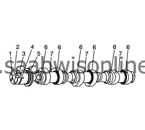
1.
|
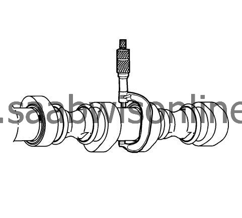
Inspect the camshaft oil feed holes (1) to the camshaft position actuator for dirt, debris or blockage.
|
|
2.
|
Inspect the threaded hole (2) for damage.
|
|
3.
|
Inspect the camshaft position actuator locating notch (3) for damage or wear.
|
|
4.
|
Inspect the camshaft sealing grooves (4) for damage.
|
|
5.
|
Inspect the camshaft thrust surface (5) for damage.
|
|
6.
|
Inspect the camshaft lobes (6) and journals (7) for the following conditions:
|
|
|
•
|
Excessive scoring or pitting
|
|
|
•
|
Discoloration from overheating
|
|
|
•
|
Deformation from excessive wear, especially the camshaft lobes
|
|
7.
|
If any of the above conditions exist on the camshaft, replace the camshaft.
|
|
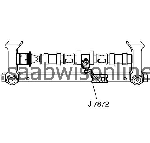
1.
|
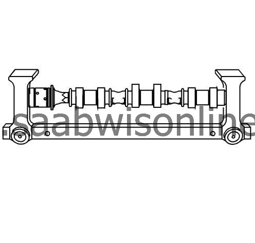
With the camshaft in a suitable fixture, measure the camshaft for wear.
|
|
|
•
|
If the diameter is smaller than specifications, replace the camshaft.
|
|
|
•
|
If the out-of-round exceeds specifications, replace the camshaft.
|
|
6.
|
If the camshaft is damaged or worn beyond specifications, replace the camshaft. No machining of the camshaft is allowed.
|
|
7.
|
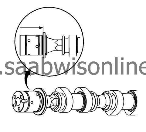
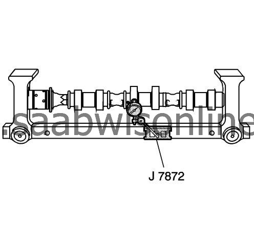
Measure the camshaft lobes for wear using the
EN 49474
indicator.
|
|
8.
|
Place the
EN 49474
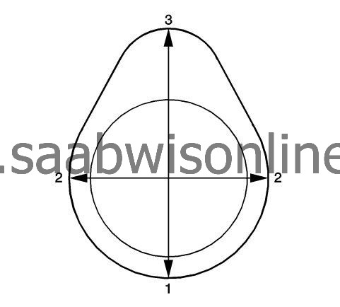
indicator with the indicator tip on the base circle (1) of the camshaft lobe.
|
|
|
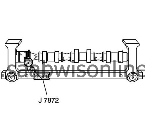
8.1.
|
Place the
EN 49474
indicator at zero .
|
|
|
8.2.
|
Rotate the camshaft until the indicator tip is at the highest point (3) on the lobe. This reading is the lift of the camshaft lobe. Refer to
Engine Mechanical Specifications
.
|
|
|
8.3.
|
If the indicated measurement is significantly lower than these specifications, replace the camshaft or engine performance will be reduced.
|