Crankshaft and Bearing Cleaning and Inspection
|
|
Crankshaft and Bearing Cleaning and Inspection
|
|
1.
|
Clean the following components in solvent:
|
|
|
•
|
Crankshaft oil passages
|
|
|
•
|
Crankshaft threaded holes
|
|
2.
|
 Warning
|
|
Wear safety glasses when using compressed air, as flying dirt particles may cause eye injury.
|
|
|
|
|
|
Dry the following components with compressed air:
|
|
|
•
|
Crankshaft oil passages
|
|
|
•
|
Crankshaft threaded holes
|
|
1.
|
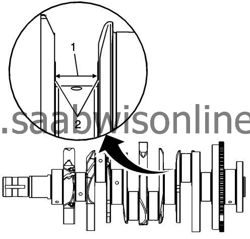
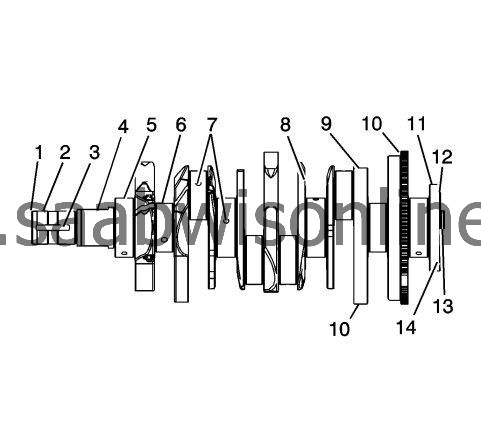
Perform the following visual inspections:
|
|
|
•
|
Inspect the crankshaft balancer bolt hole (1) for thread damage.
|
|
|
•
|
Inspect the crankshaft balancer mounting area (2) for damage.
|
|
|
•
|
Inspect the crankshaft keyway (3) for damage.
|
|
|
•
|
Inspect the oil pump drive flats (4) for damage.
|
|
|
•
|
Inspect the crankshaft main journals (5) for damage.
|
|
|
•
|
Inspect the crankshaft connecting rod journals (6) for damage.
|
|
|
•
|
Inspect the crankshaft oil passages (7) for obstructions.
|
|
|
•
|
Inspect the crankshaft main bearing thrust wall surfaces (8) for damage.
|
|
|
•
|
Inspect the crankshaft counterweights (9) for damage.
|
|
|
•
|
Inspect the crankshaft reluctor ring teeth (10) for damage.
|
|
|
•
|
Inspect the crankshaft rear main oil seal surface (11) for damage.
|
|
|
•
|
Inspect the crankshaft engine flywheel mounting surface (12) for damage.
|
|
|
•
|
Inspect the crankshaft pilot hole (13) for damage.
|
|
|
•
|
Inspect the crankshaft engine flywheel bolt holes (14) for thread damage.
|
|
2.
|
Repair or replace the crankshaft as necessary.
|
|
Crankshaft Bearing Inspection
|
|
1.
|
|
Note
|
|
•
|
All connecting rod and main journal bearings that have been used in a running engine must be replaced. Never re-use the crankshaft or connecting rod bearings.
|
|
•
|
The following bearing wear conditions should be used to diagnose engine operating conditions or root cause of a condition.
|
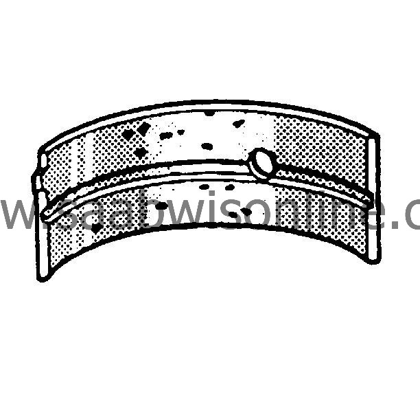
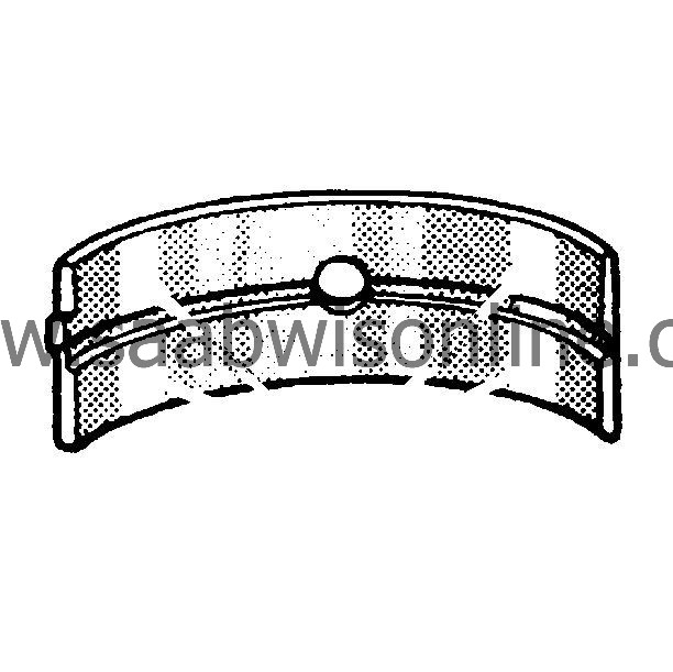
Inspect for fatigue indicated by craters or pockets. Flattened sections on the bearing halves also indicate fatigue.
|
|
2.
|
Inspect for excessive scoring or discoloration on both front and back of the bearing halves.

|
|
3.
|
Inspect the main bearings for dirt embedded into the bearing material.
|
|
4.
|
Inspect for improper seating indicated by bright, polished sections.
|
Special Tools
EN-49474
Magnetic Base Dial Indicator
For equivalent regional tools, refer to
Special Tools
.
|
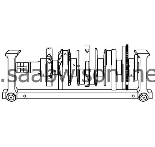
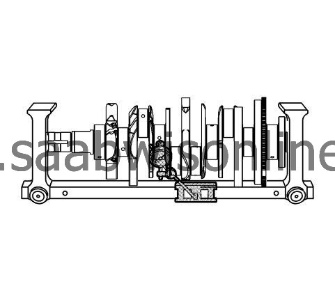
1.
|
Using a suitable fixture, support the crankshaft.
|
|
2.
|
Install the
EN 49474
indicator.
|
|
6.
|
If the crankshaft journals are damaged or worn beyond specifications, the crankshaft may be ground 0.25 mm (0.010 in). There is only 1 size of oversized main bearings available for service.
|
|
7.
|
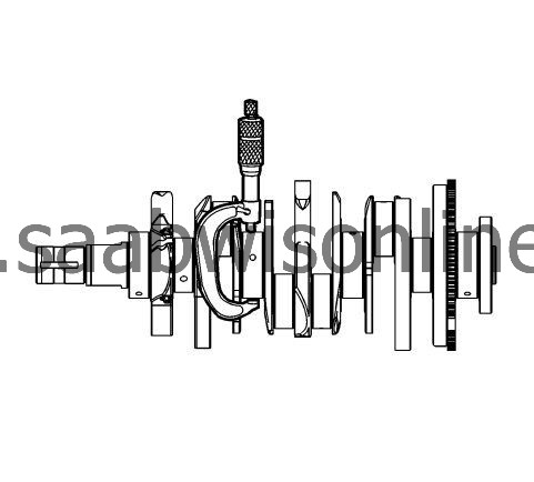
Inspect the crankshaft main journals for undersize, using an outside micrometer.
|
|
8.
|
Inspect the crankpins for undersize using an outside micrometer.
|
|
9.
|
Compare your measurements with those listed in the
Engine Mechanical Specifications
. If the crankpin journals are worn beyond the specifications, the crankshaft may be ground 0.25 mm (0.010 in). There is only 1 size of oversized connecting rod bearings available for service.
|
|
10.
|
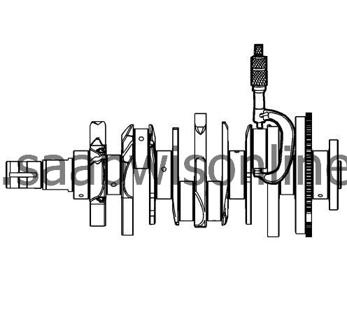
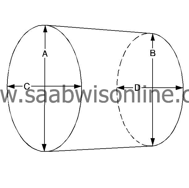
Measure the main bearing and crankpin journals for out-of-round using the following procedure:
|
|
|
10.1.
|
Using an outside micrometer, measure the journal at the extreme front and rear locations on the journal. Call these points A and B.
|
|
|
10.2.
|
Measure the journal in 2 new locations exactly 90 degrees from the first points. Call these points C and D.
|
|
|
10.3.
|
Subtract A from C and B from D. The differences will indicate journal out-of-round.
|
|
|
10.4.
|
The out-of-round should not exceed 0.004 mm (0.00016 in) maximum.
|
|
|
10.5.
|
If the journals are worn beyond the specifications, the crankshaft may be ground 0.25 mm (0.010 in). There is only 1 size of oversized crankshaft and connecting rod bearings available for service.
|
|
11.
|
Measure the main bearing and crankpin journals for taper using the following procedure:
|
|
|
11.1.
|
Using an outside micrometer, measure the journal at the extreme front (A) and rear (B) of the journal parallel to the crankshaft centerline.
|
|
|
11.2.
|
Subtract the smallest from the largest measurement. The result will be the journal taper.
|
|
|
11.3.
|
If the main bearing journal taper exceeds 0.004 mm (0.00016 in), replace the crankshaft.
|
|
|
11.4.
|
If the journals are worn beyond the specifications, the crankshaft may be ground 0.25 mm (0.010 in). There is only 1 size of oversized crankshaft and connecting rod bearings available for service.
|