Crankshaft and Bearing Installation
|
|
Crankshaft and Bearing Installation
|
Special Tools
|
•
|
DT-8390270
Slide Hammer
|
|
•
|
EN 45059
Torque Angle Sensor Kit
|
|
•
|
EN 41818
Crankshaft Bearing Cap Remover
|
For equivalent regional tools, refer to
Special Tools
.
|
Crankshaft Bearing Installation Procedure
|
|
Note
|
|
If the crankshaft bearings have been used in a running engine, you must replace them with NEW crankshaft bearings for reassembly.
|
|
1.
|
Clean the crankcase crank bore with a lint-free cloth.
|
|
2.
|
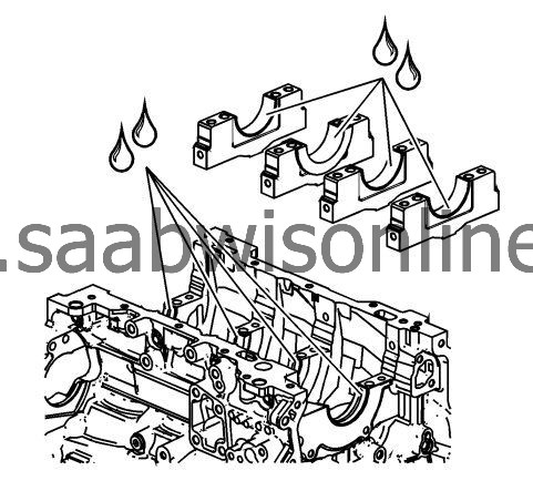
Clean all the oil from the backside of new bearing halves.
|
|
3.
|
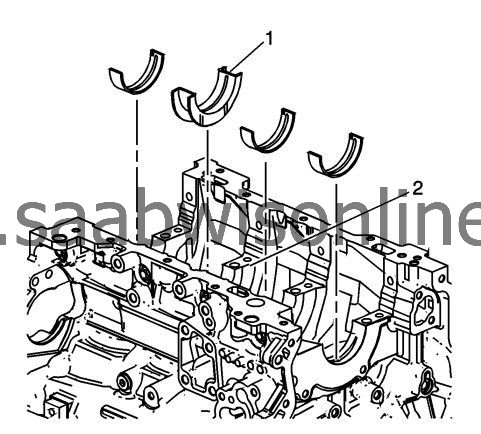
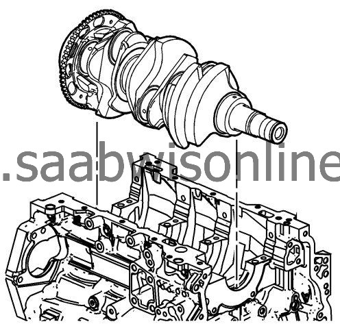
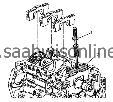
Install the new upper crankshaft bearing halves to the cylinder block. Note the position of the thrust bearing (1) at the number 3 journal (2).
|
|
4.
|
Ensure that the upper bearing insert contains the oil transfer hole and groove. Roll the bearing into position so that the lock tang engages the crank slot. The bearing must fit flush with the upper crankcase.
|
|
5.
|
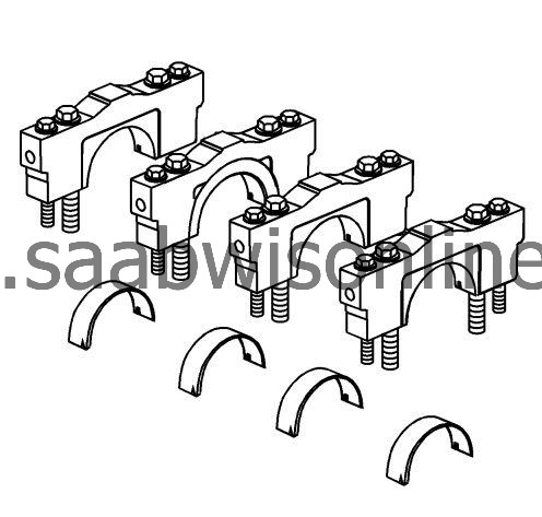
Install the new lower crankshaft bearings into position in the main bearing caps.
|
|
6.
|
The lower crankshaft bearings are identified by NO grooves or holes. The bearings must fit flush with the crankshaft bearing caps.
|
|
Crankshaft Installation Procedure
|
|
1.
|
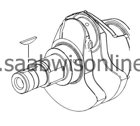
If removed, install the crankshaft key. Lightly tap the key in place with a small soft face, bronze/plastic, hammer until it bottoms in the keyway.
|
|
2.
|
Gently lower the crankshaft into position in the cylinder block.
|
|
Crankshaft Bearing Clearance Measurement Procedure
|
|
1.
|
Place a length of fresh, room temperature plastic gaging material all the way across all the crankshaft bearing journals.
|
|
2.
|
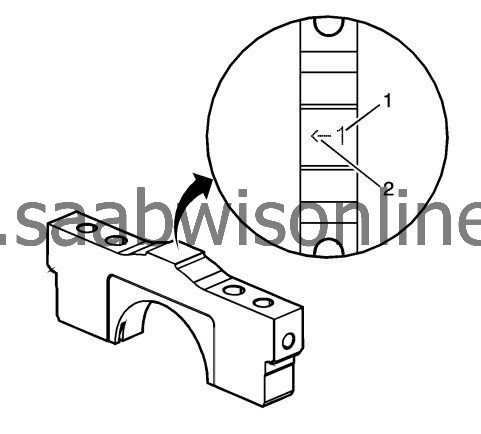
Identify the proper order of the main bearing caps. The main bearing caps are numbered 1 (1) through 4, with the front main bearing cap marked with the number 1. The arrow (2) is to be oriented to the front of the engine.
|
|
3.
|
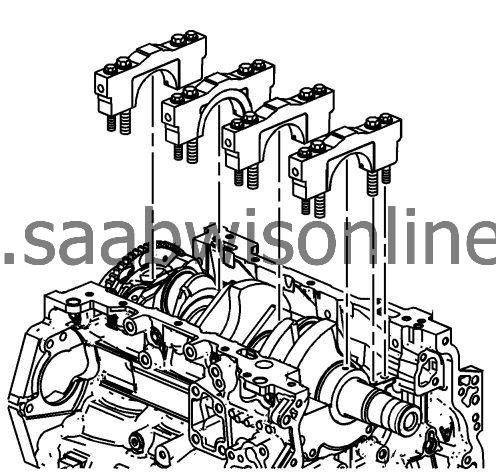
Install the crankshaft main bearing caps.
|
|
4.
|
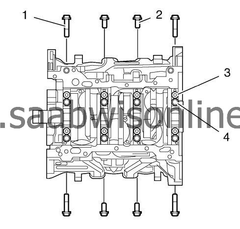
Loosely install the original inner main cap bolts (4).
|
|
5.
|
Loosely install the original outer main cap bolts (3).
|
|
6.
|
Loosely install the original short/inner side main cap bolts (2).
|
|
7.
|
Loosely install the original long/outer side main cap bolts (1).
|
|
8.
|
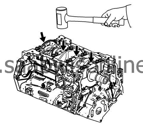
Tap the crankshaft main bearing caps with a soft-faced hammer.
|
|
9.
|
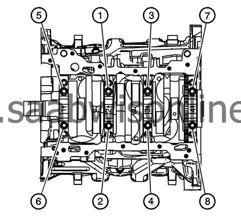
Tighten the main caps bolts in the sequence as shown using the
EN 45059
angle meter.
|
|
10.
|
Refer to
Fastener Caution
.
Tighten the inboard bolts (1-8) first, in 2 passes:
|
|
|
10.1.
|
Tighten the inboard bolts (1-8) to
20 Nm (15 lb ft)
on the first pass.
|
|
|
10.2.
|
Tighten the inboard bolts (1-8) an additional
80 degrees
on the 2nd pass.
|
|
11.
|
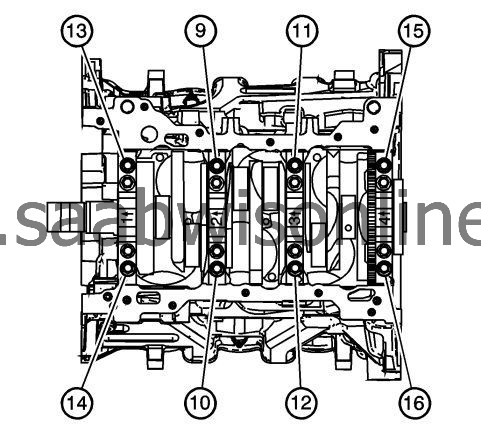
Tighten the outboard bolts (9-16) second, in 2 passes:
|
|
|
11.1.
|
Tighten the inboard bolts (9-16) to
15 Nm (11 lb ft)
on the first pass.
|
|
|
11.2.
|
Tighten the inboard bolts (9-16) an additional
110 degrees
on the 2nd pass.
|
|
12.
|
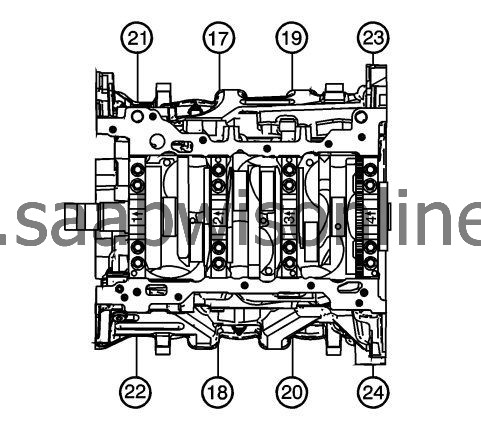
Tighten the main caps side bolts in the sequence as shown using the
EN 45059
angle meter.
|
|
13.
|
Tighten the short/inner bolts (17-20) third, in 2 passes.
|
|
|
13.1.
|
Tighten the short/inboard bolts (17-20) to
30 Nm (22 lb ft)
on the first pass.
|
|
|
13.2.
|
Tighten the short/inner bolts (17-20) an additional
60 degrees
on the 2nd pass.
|
|
14.
|
Tighten the long/outer bolts (21-24) fourth, in 2 passes.
|
|
|
14.1.
|
Tighten the long/outboard bolts (21-24) to
30 Nm (22 lb ft)
on the first pass.
|
|
|
14.2.
|
Tighten the long/outer bolts (21-24) an additional 60 degrees on the 2nd pass.
|
|
15.
|
|
Note
|
|
Do not rotate the crankshaft.
|
After reaching final torque, allow the assembly to sit for 2 minutes.
|
|
16.
|
Remove the 8 crankshaft bearing cap side bolts (1) and (2).
|
|
17.
|
Remove the 8 crankshaft bearing cap outer bolts (3).
|
|
18.
|
Remove the 8 crankshaft bearing cap inner bolts (4).
|
|
19.
|
Remove the crankshaft bearing caps using the
DT 8390270
slide hammer (1) and
EN 41818
remover (2).
|
|
20.
|
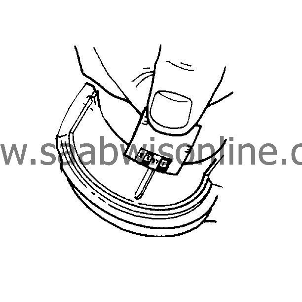
Determine the crankshaft bearing clearance by comparing the width of the flattened plastic gaging material at its widest point with the graduation on the gaging material container.
|
|
21.
|
|
Note
|
|
The crankshaft bearings CAN be reused after checking the clearance if the bearings have never been used in a running engine.
|
Compare your measurements with the Engine Mechanical Specifications. Refer to
Engine Mechanical Specifications
. If the new bearings do not provide the proper crankshaft to bearing clearance, inspect the following:
|
|
|
•
|
Re-measure the crankshaft journals for the correct specified size and ensure the proper new bearings are being installed. If the crankshaft journals are incorrectly sized, replace or regrind the crankshaft. Crankshaft machining is permitted and undersized bearings are available.
|
|
|
•
|
Re-measure the engine block crankshaft bearing bore diameter to ensure proper size. The crankshaft bearing hole in the engine block cannot be machined. If the diameter is incorrect, the block must be replaced.
|
|
22.
|
Clean the plastic gaging material from the crankshaft bearing journals with a soft, lint-free cloth.
|
|
23.
|
Lift the crankshaft out of the cylinder block.
|
|
25.
|
Gently lower the crankshaft into position in the cylinder block.
|
|
26.
|
Identify the proper order of the main bearing caps. The main bearing caps are numbered 1 (1) through 4, with the front main bearing cap marked with the number 1.
The arrow (2) is to be oriented to the front of the engine.
|
|
27.
|
Install the crankshaft main bearing caps.
|
|
28.
|
Loosely install the NEW inner main cap bolts.
|
|
29.
|
Loosely install the NEW outer main cap bolts.
|
|
30.
|
|
Note
|
|
The side main cap bolts originally have a sealant on the flange of the bolt head. NEW bolts must be used. If NEW bolts are not used, oil can leak from the crankcase past the bolts.
|
Loosely install the NEW inner main cap bolts (4).
|
|
31.
|
Loosely install the NEW outer main cap bolts (3).
|
|
32.
|
Loosely install the NEW short/inner side main cap bolts (2).
|
|
33.
|
Loosely install the NEW long/outer side main cap bolts (1).
|
|
34.
|
Tap the crankshaft main bearing caps with a soft-faced hammer.
|
|
35.
|
Tighten the main caps bolts in the sequence as shown using the
EN 45059
angle meter.
|
|
36.
|
Tighten the inboard bolts (1-8) first, in 2 passes:
|
|
|
36.1.
|
Tighten the inboard bolts (1-8) to
20 Nm (15 lb ft)
on the first pass.
|
|
|
36.2.
|
Tighten the inboard bolts (1-8) an additional
80 degrees
on the 2nd pass.
|
|
37.
|
Tighten the outboard bolts (9-16) second, in 2 passes:
|
|
|
37.1.
|
Tighten the inboard bolts (9-16) to
15 Nm (11 lb ft)
on the first pass.
|
|
|
37.2.
|
Tighten the inboard bolts (9-16) an additional
110 degrees
on the 2nd pass.
|
|
38.
|
Tighten the main caps side bolts in the sequence as shown using the
EN 45059
angle meter.
|
|
39.
|
Tighten the short/inner bolts (17-20) third, in 2 passes.
|
|
|
39.1.
|
Tighten the short/inboard bolts (17-20) to
30 Nm (22 lb ft)
on the first pass.
|
|
|
39.2.
|
Tighten the short/inner bolts (17-20) an additional
60 degrees
on the 2nd pass.
|
|
40.
|
Tighten the long/outer bolts (21-24) fourth, in 2 passes.
|
|
|
40.1.
|
Tighten the long/outboard bolts (21-24) to
30 Nm (22 lb ft)
on the first pass.
|
|
|
40.2.
|
Tighten the long/outer bolts (21-24) an additional
60 degrees
on the 2nd pass.
|
|
41.
|
Ensure that the crankshaft turns without binding or noise.
|