PRE-RELEASE
Piston and Connecting Rod Assemble
| Piston and Connecting Rod Assemble |
Special Tools
| • |
EN 46121
Connecting Rod Guide Pin Set
|
|
| • |
EN 46745
Piston Pin Clip Remover/Installer
|
|
For equivalent regional tools, refer to Special Tools .
| Piston and Piston Pin Installation Procedure |
| 1. |
Lubricate the piston pin bores in the piston and the connecting rod with or equivalent. Refer to Adhesives, Fluids, Lubricants, and Sealers for the recommended lubricant. 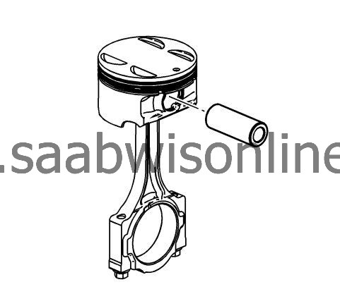
|
|||||||
| 2. |
Assemble the piston and piston pin to the connecting rod. Properly orient the piston when reusing a marked connecting rod.
|
|
| 3. |
Align the piston pin bore with the connecting rod pin bore.
|
|
| 4. |
Slide the piston pin into the piston and the connecting rod.
|
|
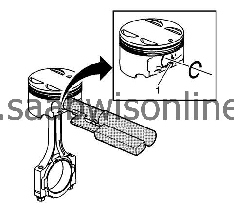
| 6. |
Ensure that the piston pin retainers are fully seated in their grooves.
|
|
| 7. |
Repeat these procedures for the remaining pistons.
|
|
| Piston Ring Installation Procedure |
| 1. |
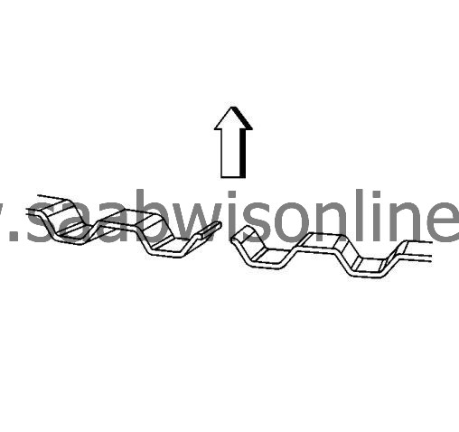
Properly orient the oil control ring expander as shown before installation. The ends of the expander must be facing toward the top of the piston.
|
|
| 2. |
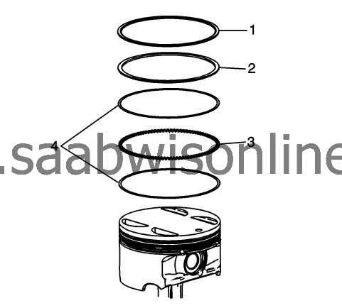
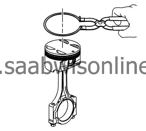
Using a piston ring expander, install the oil control ring assembly using the following procedure:
|
|
| 2.1. |
Install the expander ring (3).
|
| 2.2. |
Install the 2 oil scraper rings (4). Expand the rings only enough to clear the piston diameter. Overexpanding the piston rings will distort or crack the rings.
|
| 3. |
Install the second and top piston rings using the ring expander. Ensure that you do not overexpand the rings.
|
|
| 4. |
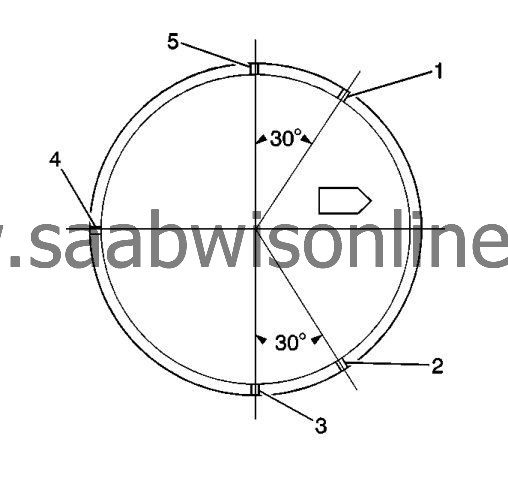
Once the rings are installed, set the ring gaps for the oil control, second and top ring as follows. Use the piston location arrow for reference.
|
|
| 4.1. |
Lower oil control ring - position 1
|
| 4.2. |
Upper oil control ring - position 2
|
| 4.3. |
Top Ring - position 3
|
| 4.4. |
Oil control ring expander - position 4
|
| 4.5. |
Second ring - position 5
|
| Connecting Rod Bearing Installation Procedure |
| 1. |
Clean the connecting rod and the connecting rod cap bearing bore with a lint-free cloth. 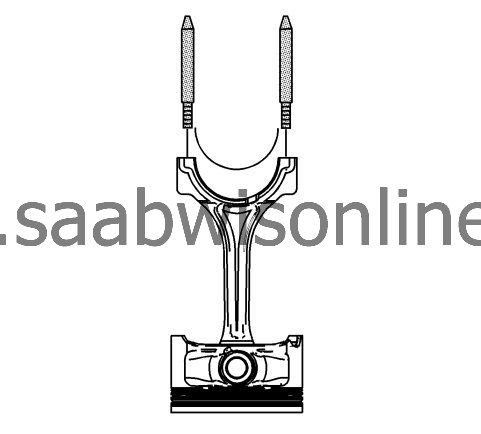
|
|||||||
| 2. |
Clean all the oil from behind the connecting rod bearing halves.
|
|
| 3. |
Install new upper connecting rod bearings into position. Roll the bearing into position so that the lock tang engages the alignment slot. The bearing must fit flush in the connecting rod.
|
|
| 4. |
Install the
EN 46121
pin into the connecting rod bolt holes.
|
|
| 5. |
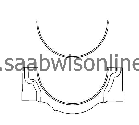
Install new lower connecting rod bearings into position in the connecting rod cap. Roll the bearing into position so that the lock tang engages the alignment slot. The bearings must fit flush with the connecting rod cap.
|
|

