PRE-RELEASE
Headlamp Aiming (Check and Adjust)
| Headlamp Aiming (Check and Adjust) |
76/756 EEC or ECE-R48 guidelines cover checking and adjustment of headlamps on vehicle. Correct adjustment of headlamps on vehicle should enable optimal road illumination by low beam, with minimal dazzling of oncoming traffic. To this end, inclination of headlamp beam to level road surface and angle of beam to vertical longitudinal plane running through vehicle centre must satisfy conditions laid down in guidelines.
Dazzling (low beam) is considered eliminated if intensity of illumination at a distance of 25 m (82 ft) from each individual headlamp on the plane perpendicular to the road and at height of headlamp as well as beyond, is not greater than 1 lux. This requirement is generally satisfied if headlamp adjustment is carried out according to adjustment guidelines.
Main headlamp housing or retainer displays reference 1.0 percent for low beam adjustment according to EEC 76/756 or ECE-R48 guidelines.
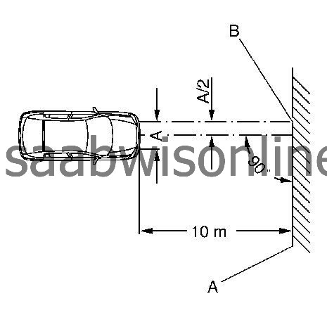
Reference 1.0 percent corresponds to the adjustment dimension of the headlamp with reference to the inclination of the light beam. The inclination at a distance of 10 m (33 ft) from vehicle headlamp is therefore 10 cm (4 in). The inclination of the dipped beam headlamp is indicated by its light/dark boundary.
The adjustment guideline is clarified by the following two illustrations.
B = Central marking
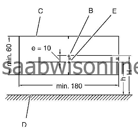
C = Test surface
D = Road surface
E = Break point
e = Adjustment dimension in cm, e = H - h (adjustment dimension, main headlamps 1.0 percent, e = 10 cm (4 in), front fog lamps 2 percent, e = 20 cm (8 in))
H = Height of centre of headlamp over road surface
h = Height of light/dark boundary line of dipped beam above road surface
The headlamp adjustment is performed according to the specifications, as shown in the illustrations, using an adjuster. When using a headlamp adjuster, ensure that vehicle tire area in contact with the road and the surface for setting up the adjuster are level and parallel with one another.
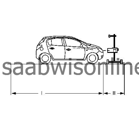
The surface on which the measuring instrument and the vehicle stand must be flat. The level of the ground must not vary by more than ± 0.5 mm / m .
| • |
I =
± 0.1 mm / m
|
|
| • |
II =
± 0.5 mm / m
|
|
Vehicle tires must have specified air pressure. Defective headlamp lenses and mirrors as well as blackened bulbs must be replaced before adjusting.
The adjustment is performed at vehicle curb weight plus one person or 75 kg (165 lb) on the driver's seat. (Curb weight = weight of vehicle ready for use with completely filled fuel tank plus the weight of all equipment carried during use, e.g. spare wheel, tools, jack, first aid kit, emergency warning triangle, etc.).
Vehicles with manual level control must be adjusted to the specified basic pressure (0.8 bar at curb weight).
If manual headlamp range control is fitted, switch the ignition on and position the adjuster wheel of the light switch centre to "0".
The intersection between the horizontal and the ascending parts of the light/dark boundary (break point) must lie on the perpendicular through the central marking.
For easier determination of the intersection point, headlamp halves can be alternately covered and uncovered.
The headlamp adjusting equipment used must comply with the existing guidelines and the manufacturer's operating instructions must be observed.
The headlamp adjuster must be regularly checked by manufacturer's maintenance service.
The headlamp adjuster is set up according to manufacturer's guidelines and is adjusted to 1.0 percent inclination for the low beam or 2 percent inclination for the fog lamp.
According to the directive 76/756, EEC the 15 degree line is no longer required for the dipped beam on the measurement screen. The adjustment direction can also be undertaken with headlamp adjustment equipment which shows the 15 degree line on the measurement screen.

In headlamps where the main and dipped beam can be adjusted, the centre of the main beam must lie within the boundary corners around the central mark.
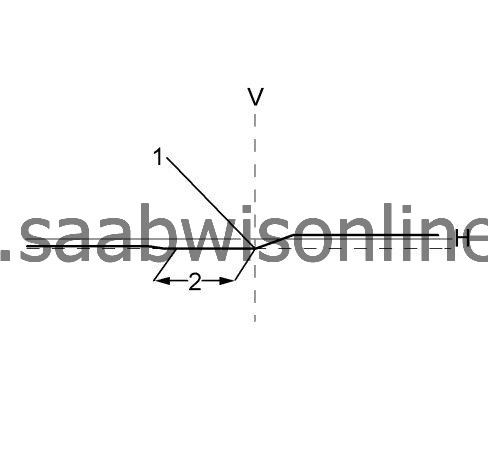
Only Vehicle with AFL
1= Break point to the side setting in line V
2= Setting of the height by means of brightly darkness border in this area in line H on 1 percent of preinclination.
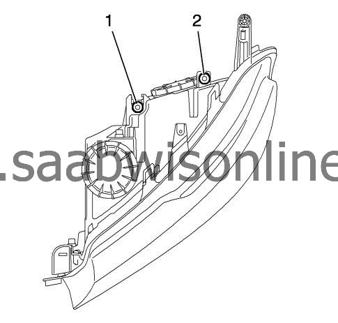
Headlamps must be adjusted using a legally specified projection wall or with optical headlamp adjuster. Adjust with bolt for vertical adjustment (1) and bolt for lateral adjustment (2).
| Note | ||
|
Turn (screw) down the light below the correct adjustment, approx. 2 full revolutions. Then turn (screw) up the light to correct adjustment. To obtain correct light adjustment, the light setting must be adjusted from below |
Vertical adjustment the light/dark boundary line left of the adjustment cross must run horizontally along the adjustment line.
| Note | ||
|
Carry out vertical adjustment first, then lateral adjustment. Check vertical adjustment again after lateral adjustment. |
Lateral adjustment the light-dark border must run horizontally from the left side up to the adjusting cross and from there on at an angle of up to approximately 15 degree towards the upper right. The beam inclination is 1.0 percent on 10 m (33 ft).
