PRE-RELEASE
Electrical Schematic Symbols
| Electrical Schematic Symbols |
Voltage Indicators
| Symbol | Description |

|
Battery Voltage
|

|
Ignition switch - Off position
|

|
Ignition switch - Accessory position
|

|
Ignition switch - Drive position
|

|
Ignition switch - Start position
|
General Icons
| Symbol | Description |

|
Master Component List Icon
This icon is used on the schematic to link to the Master Electrical Component List. |

|
Description and Operation Icon
This icon is used on the schematic to link to the Description and Operation of that particular system. |

|
Computer Programming Icon
This icon is used on the schematic to link to Control Module References, which identifies which components need programming upon replacement. |

|
Next Schematic Page Icon
This icon is used on the schematic to navigate to the next schematic in the subsystem. |

|
Previous Schematic Page Icon
This icon is used on the schematic to navigate to the previous schematic in the subsystem. |

|
Supplemental Inflatable Restraint (SIR) or Supplemental Restraint System (SRS) Icon
This icon is used to alert the technician that the system contains SIR/SRS components that require certain precautions before servicing. |

|
Information Icon
This icon is used to alert the technician that there is additional information that will aid in servicing a system. |

|
Danger - High Voltage Icon
This icon is used to alert the technician that a component/system contains 300 volt circuits. |

|
High Voltage Icon
This icon is used to alert the technician that a component/system contains voltage greater than 42 volts but less than 300 volts. |

|
Caution Icon
This icon is used to advise the technician to use caution when servicing this component. |

|
Functional Serial Data Communication
This icon is used to show the technician that the serial data circuit detail is shown incomplete. It also provides an active link to the Data Communication Schematics were the circuit is shown complete. |
Switch Position Icons
| Symbol | Description |

|
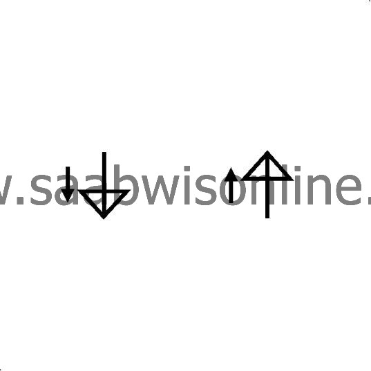
Generic Up Arrows
|

|
Generic Down Arrows
|

|
Generic Left Arrows
|

|
Generic Right Arrows
|

|
Generic Express Down Arrows
|

|
Off/On Icon
|

|
Generic Lock Icon
|

|
Generic Unlock Icon
|
|
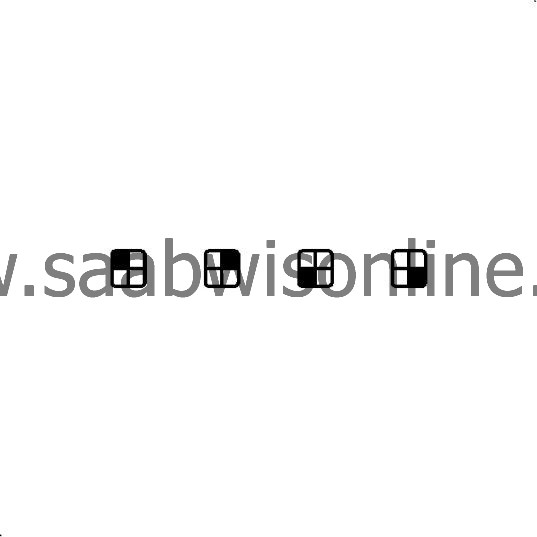
Generic Window Switch Positions - 4 Door
|

|
Generic Window Switch Positions - 2 Door
|
Module Circuit Function Icons
| Symbol | Description |
|
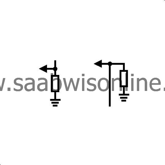
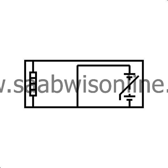
I/O Pull-Down Resistors (-)
|
|
I/O Pull-Up Resistors (+)
|

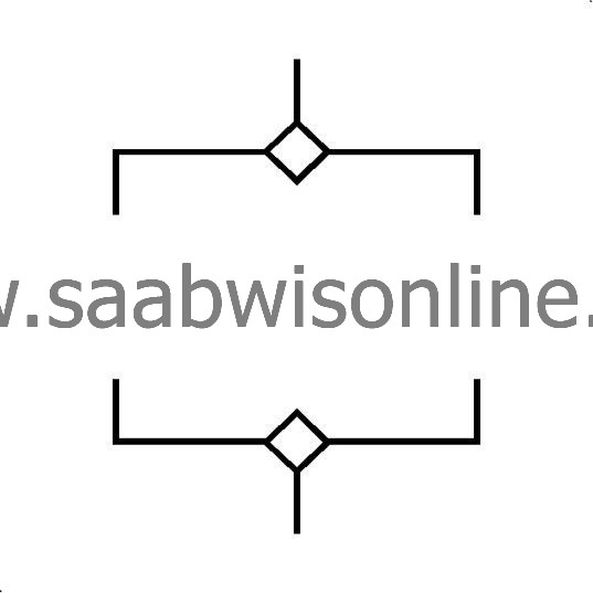
|
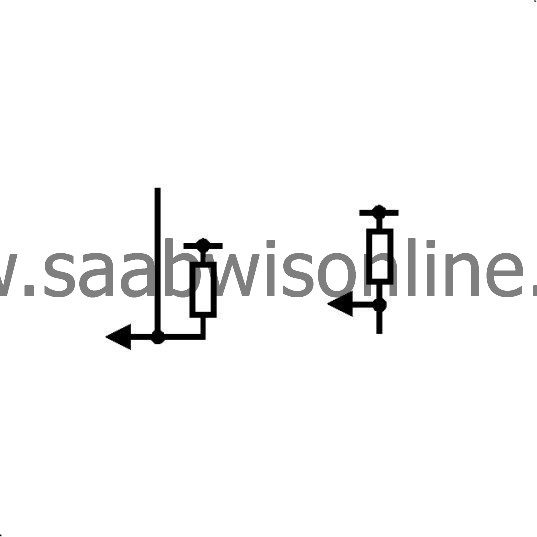
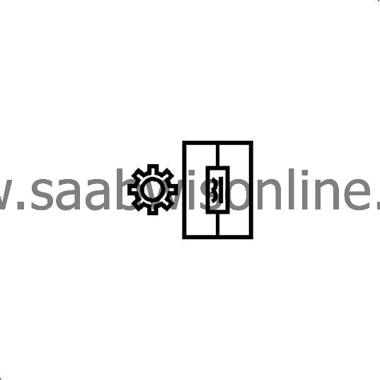
I/O High-Side Drive Switch (+)
|

|
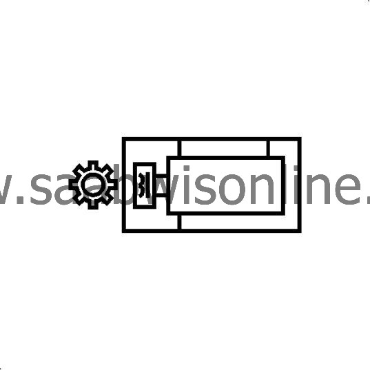
I/O Low-Side Drive Switch (+)
|
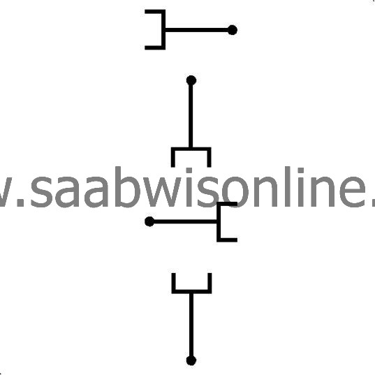
|
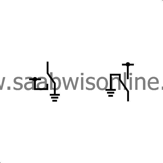
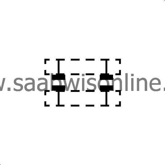
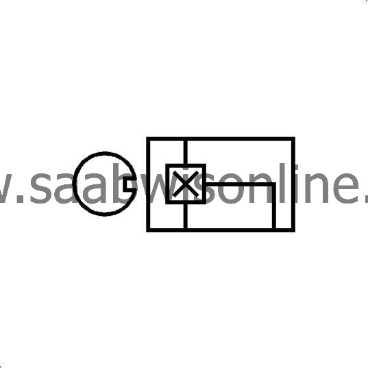
I/O Bidirectional Switch (+/-)
|

|
Pulse-Width Modulation Symbol
|

|
Battery Voltage
|

|
Ignition Voltage
|

|
Voltage Reference
|

|
A/C Voltage
|

|
Low Reference
|

|
Ground
|

|
Serial Data
|
|
Antenna Signal - In
|

|
Antenna Signal - Out
|

|
Brake Apply
|
Harness Components
| Symbol | Description |

|
Fuse
|

|
Fuse Supplied by a Relay
|

|
Overcurrent protection
|

|
Fusible Link
|

|
Ground
|

|
Case Ground
|
|
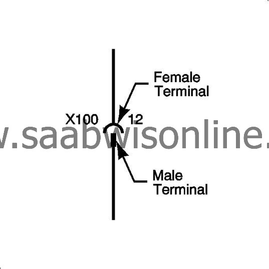
Inline Harness Connector
|
|
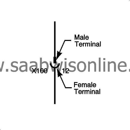
Inline Harness Connector
|
|
Pigtail Connection
|
|
Pigtail Connection
|

|
Provisional or Diagnostic Connector
|

|
Blunt Cut Wire
|

|
Incomplete Physical Splice
|

|
Complete Physical Splice - 2 Wires
|

|
Complete Physical Splice - 3 or more wires
|

|
Wire Crosses
|

|
Twisted Wires
|
|
Shield
|
|
Circuit References
|

|
Circuit Continuation Arrowheads
|
|
Option Breakpoint
|

|
Ground Circuit Connection
|

|
Connector Shorting Clip
|
Component Parts
| Symbol | Description |

|
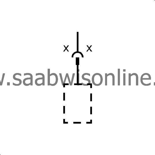
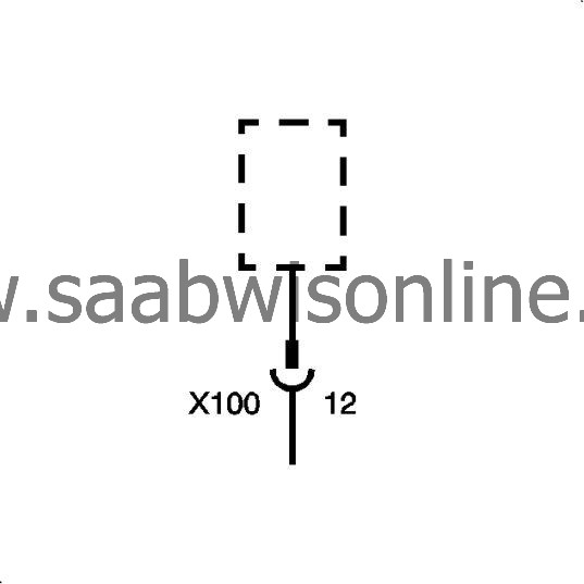
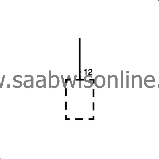
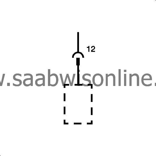
Partial Component
When a component is represented in a dashed box, the component or its wiring is not shown in its entirety. |

|
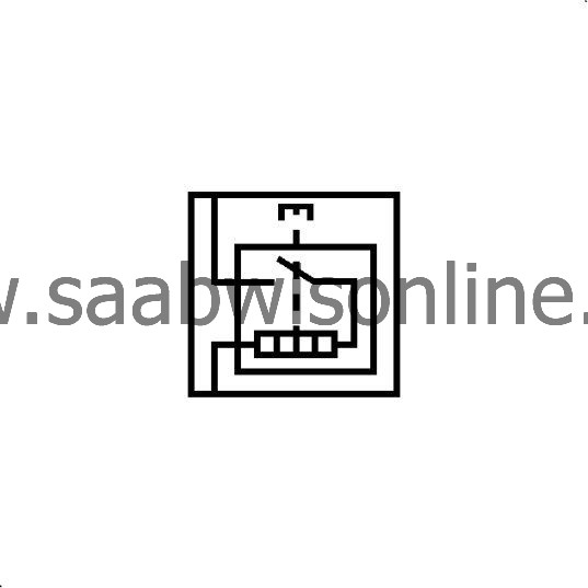
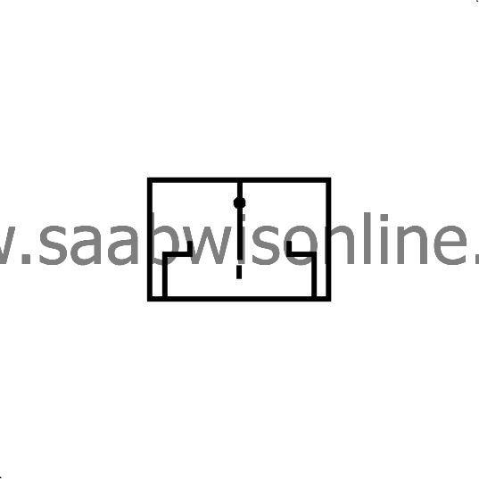
Entire Component
When a component is represented in a solid box the component or its wiring is shown in its entirety. |
|
Connector Directly Attached to Component
|
|
Pigtail Connector
|
Switches and Relays
| Symbol | Description |

|
Accessory Power Outlet
|
|
Cigarette lighter
|

|
Switch - 2 Position, Normally Open
|

|
Switch - 2 Position, Normally Closed
|
|
Switch - Rocker
|

|
Switch - Contact Plate (1 Wire)
|
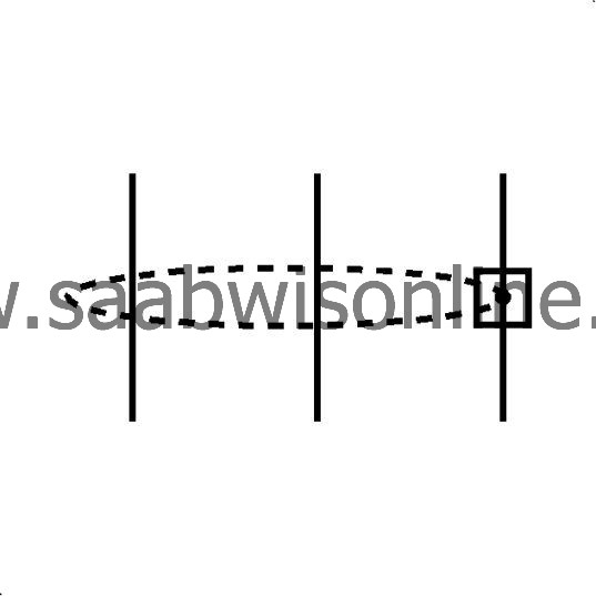
|
Switch - Contact Plate (2 Wire)
|

|
Switch - 3 Position
|

|
Switch - 4 Position
|

|
Switch - 5 Position
|

|
Switch - 6 Position
|

|
Switch Actuator - Push (Momentary)
|

|
Switch Actuator - Push (Latching)
|

|
Switch Actuator - Pull (Momentary)
|

|
Switch Actuator - Pull (Latching)
|

|
Switch Actuator - Rotate (Momentary)
|

|
Switch Actuator - Rotate (Latching)
|

|
Switch Actuator - Slide (Momentary)
|

|
Switch Actuator - Slide (Latching)
|

|
Switch Actuator - Push (Momentary)
|

|
Switch Actuator - Temperature (Momentary)
|

|
Switch Actuator - Volume (Latching)
|
|
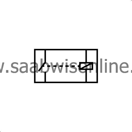
4-Pin Single Pole Relay/Throw Relay - Normally Open
|
|
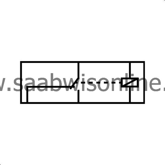
5-Pin Relay - Normally Closed
|
Devices and Sensors
| Symbol | Description |
|
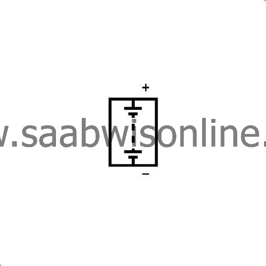
Battery
|

|
Battery Assembly - Hybrid
|

|
Single Filament Light Bulb
|

|
Double Filament Light Bulb
|

|
Light Emitting Diode (LED)
|

|
Photo Sensor
|

|
Gauge
|

|
Diode
|

|
Capacitor
|

|
Resistor
|

|
Adjustable resistor
|

|
NTC resistor
|

|
Breakable Wire
|

|
Heating Element
|

|
Position Sensor
|

|
Pressure Sensor
|

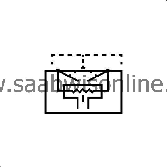
|
Knock Sensor
|
|
Inductive sensor - 2-wire
|
|
Inductive sensor - 3-wire
|

|
Hall sensor - 2-wire
|
|
Hall sensor - 3-wire
|

|
Oxygen sensor - 2-wire
|
|
Heated oxygen sensor - 4-wire
|

|
Solenoid - Actuator
|

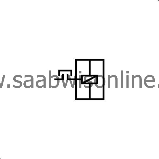
|
Solenoid - Valve
|
|
Clutch
|

|
Engine
|
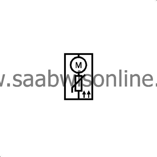
|
Motor with PTC-resistor
|

|
Antenna
|

|
Speaker
|

|
Horn
|

|
Microphone
|
|
Airbag
|

|
SIR Coil
|

|
SIR Impact Sensor
|
