Front Wheel Drive Shaft and Intermediate Shaft Assembly Replacement - Right Side (Diesel, FWD)
|
|
Front Wheel Drive Shaft and Intermediate Shaft Assembly Replacement - Right Side (Diesel, FWD)
|
Special Tools
|
•
|
CH-49376
Holding Wrench
|
|
•
|
CH-49400
Hub Spindle Remover
|
For equivalent regional tools, refer to
Special Tools
.
|
1.
|
 Warning
|
|
To prevent personal injury and/or component damage, do not allow the weight of the vehicle to load the front wheels, or attempt to operate the vehicle, when the wheel drive shaft(s) or wheel drive shaft nut(s) are removed. To do so may cause the inner bearing race to separate, resulting in damage to brake and suspension components and loss of vehicle control.
|
|
|
|
|
|
|
Warning
|
|
Wheel drive shaft boots, seals and clamps should be protected from sharp objects any time service is performed on or near the wheel drive shaft(s). Damage to the boot(s), the seal(s) or the clamp(s) may cause lubricant to leak from the joint and lead to increased noise and possible failure of the wheel drive shaft.
|
|
|
|
|
|
Raise and suitably support the vehicle. Refer to
Lifting and Jacking the Vehicle
.
|
|
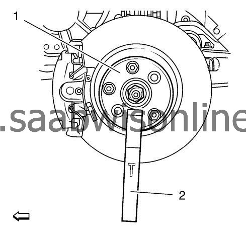
3.
|
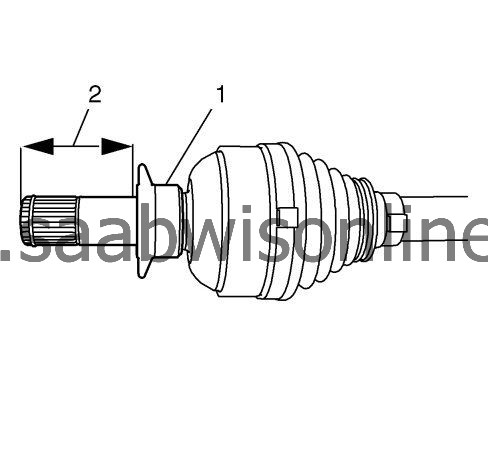
Using the
CH-49376
holding wrench (1) with
EN-956-1
extension (2).
|
|
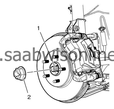
4.
|
|
Note
|
|
DO NOT re-use the wheel drive shaft nut. Discard the nut and replace with NEW.
|
Remove the wheel drive shaft nut (2) from the wheel drive shaft (1).
|
|
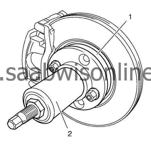
5.
|
|
Warning
|
|
Hang up the brake caliper with heavy-duty steel wire or the like. This applies on all occasions when the yoke is removed from the bracket and the brake hose is still connected. Failure to support the caliper in this manner will cause the flexible brake hose to bear the weight of the caliper, which may cause damage to the brake hose and in turn may cause a brake fluid leak.
|
|
|
|
|
|
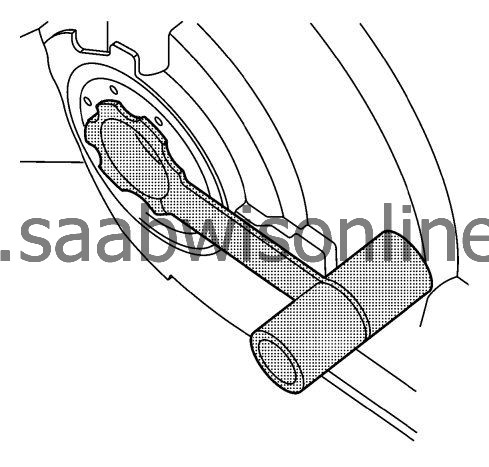
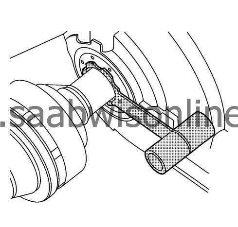
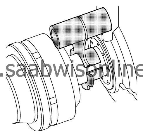
Using the
CH-49400
remover (2), separate the brake rotor and wheel bearing/hub assembly (1).
|
|
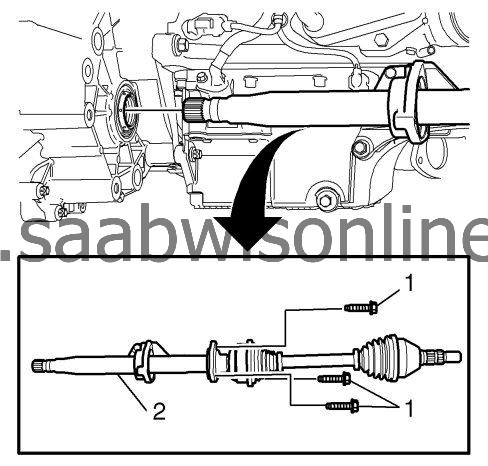
9.
|
Remove the fasteners (1) from the intermediate flange.
|
|
10.
|
|
Note
|
|
Discard the complete assembly.
|
Remove the wheel drive shaft and intermediate shaft assembly (2) through bracket.
|
|
1.
|
Clean the mating faces of the intermediate shaft and the drive shaft.
Possible cleaner: brake cleaner (i.e. Loctite 7063)
|
|
2.
|
Assemble rubber slinger (1).
|
|
3.
|
|
Note
|
|
It is not possible to install the bearing after the bonding is made.
|
Assemble bearing and flange onto intermediate shaft.
|
|
4.
|
Apply Loctite 262 only to the drive shaft in the position shown (2). Container and brush have to be free from metal if used more than once.
|
|
5.
|
Assemble drive shaft and intermediate shaft.
The bonding process takes 12 hours at room temperature. Let the bonding age either prior reinstallation into the car or after reinstallation. The vehicle must not be driven or moved when the adhesive dries. The vehicle can be pushed to a parking place while the adhesive dries.
|
|
6.
|
Install the
DT-6332
protector into the differential output shaft seal.
|
|
7.
|
Reinstall the drive shaft and the intermediate shaft through the bracket onto the engine.
|
|
8.
|
|
Note
|
|
In order to prevent lubricant leaks, use care when installing the wheel drive shaft to the differential. Do not damage the oil seal. Replace the oil seal if it becomes nicked, distorted, or otherwise damaged.
|
Carefully install the intermediate shaft into the differential until the splines are past the
DT-6332
protector.
|
|
9.
|
Remove the
DT-6332
protector from the differential output shaft seal.
|
|
10.
|
Install the intermediate shaft into the differential until it is fully seated.
|
|
11.
|
Refer to
Fastener Caution
.
Install the fasteners to the intermediate flange. Tighten fasteners to
22 Nm (16 lb ft)
.
|
|
12.
|
Install the front wheel drive shaft into the front wheel bearing/hub.
|
|
15.
|
Install the NEW wheel drive shaft nut (2) to the wheel drive shaft (1) tighten in 3 passes.
|
|
16.
|
Using the
CH-49376
holding wrench (1) with
EN-956-1
extension (2).
|
|
17.
|
Using a torque wrench and the appropriate size socket, tighten the wheel drive shaft nut to
150 Nm (111 lb ft)
.
|
|
|
•
|
Release the wheel drive shaft nut trough
45°
.
|
|
|
•
|
Tighten the drive shaft nut to
250 Nm (185 lb ft)
.
|
|
19.
|
|
Note
|
|
The bonding process takes 12 hours at room temperature. Let the bonding age either prior reinstallation into the car or after reinstallation.
|
|
The vehicle must not be driven or moved when the adhesive dries. The vehicle can however be pushed to a parking place while the adhesive dries.
|
Fill up the transmission fluid. Refer to
Transmission Fluid Replacement
.
|
