SIR System Description and Operation
|
|
SIR System Description and Operation
|
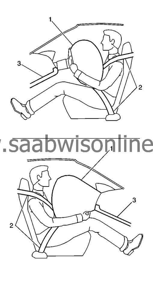
The supplemental inflatable restraint (SIR) system supplements the protection offered by the occupants Seat Belt System (2). The SIR system may contain several inflator modules located throughout the vehicle, i.e. steering wheel module (1), instrument panel module (1), or roof rail modules (1). In addition to inflator modules, the vehicle may contain seat belt pretensioners (2) that tighten the seat belt in the event of a collision, thus reducing the distance between the occupant and the seat belt when an inflator module is deployed. Each inflator module has a deployment loop that is controlled by the inflatable restraint sensing and diagnostic module (SDM) mounted inside the vehicle. The SDM determines the severity of a collision with the assistance of various sensor inputs located at strategic points on the vehicle. When the SDM detects a collision, it will process the information provided by the sensors to further support air bag or pretensioner deployment. The SDM will deploy the frontal air bags and pretensioners if it detects a collision of sufficient force. If the force of the impact is not sufficient to warrant inflator module deployment, the SDM may still deploy the seat belt pretensioners. The SDM performs continuous diagnostic monitoring of the SIR system electrical components. Upon detection of a circuit malfunction, the SDM will set a DTC and inform the driver by illuminating the AIR BAG indicator. The steering column (3) and knee bolsters (3) are designed to absorb energy and compress during frontal collisions in order to limit leg movement and decrease the chance of injury to the driver and passenger.
|
Frontal SIR System Description
|
The frontal supplemental inflatable restraint (SIR) system consists of the following components:
|
•
|
AIR BAG indicator located in the instrument cluster
|
|
•
|
Inflatable restraint sensing and diagnostic module (SDM)
|
|
•
|
Inflatable restraint passenger presence detection system
|
|
•
|
Inflatable restraint Passenger AIR BAG ON/OFF indicator
|
|
•
|
Inflatable restraint passenger frontal air bag module
|
|
•
|
Inflatable restraint seat position sensors
|
|
•
|
Inflatable restraint driver frontal air bag module
|
|
•
|
Inflatable restraint steering wheel module coil
|
|
•
|
Inflatable restraint seat belt retractor pretensioners
|
|
•
|
Inflatable restraint wiring harnesses
|
|
•
|
Steering Wheel and Column
|
|
•
|
Driver and front passenger knee bolsters
|
A frontal collision of sufficient force will deploy the frontal air bags and/or pretensioners. The inflatable restraint sensing and diagnostic module (SDM) contains a sensing device that converts vehicle velocity changes to an electrical signal. The SDM compares these signals to values stored in memory. If the signals exceed a stored value, the SDM will determine the severity of the impact and either cause current to flow through the frontal deployment loops deploying the frontal air bags and pretensioners, or it will deploy the pretensioners only. The SDM, instrument panel module, steering wheel module, steering wheel module coil, seat belt retractor pretensioners, and the connecting wires make up the frontal deployment loops. The SDM continuously monitors the deployment loops for malfunctions and illuminates the AIR BAG indicator if a fault is detected.
|
Inflatable restraint sensing and diagnostic module (SDM)
|
The inflatable restraint sensing and diagnostic module (SDM) is a microprocessor and the control center for the supplemental inflatable restraint (SIR) system. The SDM contains internal sensors along with several external sensors, if equipped, mounted at strategic locations on the vehicle. In the event of a collision, the SDM compares the signals from the internal and external sensors to a value stored in memory. When the generated signals exceed the stored value, the SDM will cause current to flow through the appropriate deployment loops to deploy the air bags. The SDM records the SIR system status when a deployment occurs and illuminates the AIR BAG indicator located in the instrument cluster. The SDM performs continuous diagnostic monitoring of the SIR system electrical components and circuitry when the ignition is turned ON. If the SDM detects a malfunction, a DTC will be stored and the SDM will request the instrument cluster to illuminate the AIR BAG indicator, notifying the driver that a malfunction exists. In the event that ignition positive voltage is lost during a collision, the SDM maintains a 23-volt loop reserve for deployment of the air bags. It is important when disabling the SIR system for servicing or rescue operations to allow the 23-volt loop reserve to dissipate, which could take up to 1 minute.
|
Inflatable Restraint Passenger Presence Detection System - If Equipped
|
|
Note
|
|
The passenger presence detection system includes an ECU and a sensor mat that can be serviced separately. After repairing or replacing any part of the passenger presence detection system, the system must be rezeroed in order to function properly.
|
The passenger presence detection system is used to monitor the weight of an occupant on the front outboard passenger seat and communicate the status to the inflatable restraint sensing and diagnostic module (SDM) whether to enable or suppress the deployment of the passenger frontal air bag module. The passenger presence detection system consist of an electronic control module, sensor mat, heated seat element (if equipped), wiring harness, and PASSENGER AIR BAG ON/OFF indicators. The sensor is made up of flexible plastic material placed underneath the seat cushion foam. Pressure on the passenger presence detection mass sensor is converted into an electrical signal that the module reads and determines the passengers classification. If the sensor determines that the occupant weight is less than a specified value, the passenger presence detection module will send a suppress signal to the SDM to disable the passenger frontal air bag module. If the sensor determines the occupant weight is higher than a specified value, the passenger presence detection module will send an enable signal to the SDM to enable the passenger frontal air bag module. The passenger presence system module will notify the customer of the enable/disable status by illuminating one of the PASSENGER AIR BAG ON/OFF indicators. The passenger presence system will also notify the SDM of a fault and the SDM will request the instrument cluster to illuminate the AIR BAG indicator.
|
Inflatable Restraint PASSENGER AIR BAG ON/OFF Indicator - If Equipped
|
The PASSENGER AIR BAG ON/OFF indicators are used to notify the driver and passenger when the passenger frontal air bag module is enabled or disabled.
The AIR BAG indicator, located in the instrument cluster and is used to notify the driver of SIR system malfunctions and to verify that the inflatable restraint sensing and diagnostic module (SDM) is communicating with the instrument cluster. When the ignition is turned ON, the SDM is supplied with ignition positive voltage. The SDM requests the instrument cluster will momentarily turn on the AIR BAG indicator. While the indicator is on, the SDM conducts tests on all SIR system components and circuits. If no malfunctions are detected the SDM will communicate with the instrument cluster through the serial data circuit and command the AIR BAG indicator OFF. The SDM monitors the airbag circuits continually by performing a number of checks. If a malfunction is detected the SDM will store a diagnostic trouble code (DTC) and command the instrument cluster to illuminate the AIR BAG indicator via serial data. The presence of a SIR system malfunction could result in non-deployment of the air bags or deployment in conditions less severe than intended. The AIR BAG indicator will remain ON until the malfunction has been repaired.
|
Dual Stage Inflator Modules
|
Dual stage inflator modules contain a housing, inflatable air bag, two initiating devices, canister of gas generating material and, in some cases, stored compressed gas. The two initiators are part of the frontal deployment loop. The function of the frontal deployment loops are to supply current through the steering wheel and instrument panel inflator modules to deploy the air bags. The inflator modules have two stages of deployment, which varies the amount of restraint to the occupant according to the collision severity. For moderate frontal collisions the inflator modules deploy at less than full deployment (low deployment) which consists of stage 1 of the inflator module. For more severe frontal collisions a full deployment is initiated which consists of stage 1 and stage 2 of the inflator module. The current passing through the initiators ignites the material in the canister producing a rapid generation of gas and is some cases, the release of compressed gas. The gas produced from this reaction rapidly inflates the air bag. Once the air bag is inflated it quickly deflates through the air bag vent holes and/or the bag fabric.
Each dual stage inflator modules is equipped with a shorting bar located in the connectors of the module. The shorting bar shorts the inflator module deployment loop circuitry to prevent unwanted deployment of the air bag when it is disconnected.
|
Inflatable Restraint Seat Belt Pretensioners
|
The seat belt retractor pretensioners consist of a housing, seat belt retractor and/or seat belt anchor, seat belt webbing, an initiator, and a canister of gas generating materials. The initiator is part of the seat belt pretensioner deployment loop. When the vehicle is involved in a collision of sufficient force, the inflatable restraint sensing and diagnostic module (SDM) causes current to flow through the seat belt deployment loops to the initiator. Current passing through the initiator ignites the material in the canister producing a rapid generation of gas. The gas produced from this reaction deploys the seat belt pretensioners and retracts the seat belt webbing, which removes all of the slack in the seat belts. Depending on the severity of the collision, the seat belt pretensioners may deploy without the frontal inflator modules deploying, or they will deploy immediately before the frontal inflator modules deploy. Each seat belt pretensioner is equipped with a shorting bar that is located in the connector of the seat belt pretensioner. The shorting bar shorts the seat belt pretensioner circuitry to prevent unwanted deployment of the seat belt pretensioner when the connector is disconnected.
|
Inflatable Restraint Seat Position Sensors - If Equipped
|
The inflatable restraint seat position sensor is used to determine the proximity of a front driver or passenger seat position with respect to the frontal air bag. The seat position sensor interfaces with the inflatable restraint sensing and diagnostic module (SDM). The state of the seat position sensor allows the SDM to disable stage 2 of the frontal air bag for a front seat that is forward of the forward/rearward point in seat track travel. The seat position sensor is a hall effect sensor that is mounted on the outboard seat track of the driver and passenger seats. The seat track includes a metal bracket that shunts the seat position sensor magnetic circuit creating 2 states of seat position. The shunted state represents a rearward seat position. The non-shunted state represents a forward position. The seat position sensor provides 2 current ranges, one range for the shunted state and a second range for a non-shunted state. These 2 states are inputs to the SDM, state 1 (shunted) being the rearward threshold and state 2 (non-shunted) being the forward threshold. When the SDM receives input from a seat position sensor that state 1 threshold is reached (seat is rearward), the SDM will not disable stage 2 deployment, if required by the deployment sensors. When state 2 threshold is reached (seat is forward), the SDM will disable stage 2 deployment on the side the seat is forward. The SDM monitors the seat position sensor circuit and if a fault is detected, the SDM will set code B0079 and disable stage 2 frontal deployment
|
Inflatable Restraint Steering Wheel Module Coil
|
The steering wheel module coil is attached to the steering column and is located under the steering wheel. The steering wheel module coil consists of two or more current-carrying coils. The coils allow the rotation of the steering wheel while maintaining continuous electrical contact between the driver deployment loop and the steering wheel module. Two or four, if equipped with dual stage air bags, coil wires are used for the steering wheel module deployment loop. Additional coil wires are used for accessories attached to the steering wheel depending on the vehicle model. The steering wheel module coil connector is located near the base of the steering column. The connector contains a shorting bar that shorts the steering wheel module coil deployment loop circuitry to prevent unwanted deployment of the air bag when servicing the inflator module.
|
Steering Column and Wheel
|
The steering wheel and columns are designed to absorb energy when driver contact is made with the steering wheel or inflated air bag. In a frontal collision the driver may come in contact with the steering wheel directly or load the steering wheel and column through the inflated air bag. When the driver applies load to the air bag or the steering wheel the column will compress downward absorbing some of the impact, helping to reduce bodily injuries to the driver. The steering wheel and column must be inspected for damages after a collision.
The knee bolsters are designed to help restrain the lower torso of front seat occupants by absorbing the energy through the front seat occupants upper legs. In a frontal collision the front seat occupant legs may come in contact with the knee bolsters. The knee bolsters are designed to crush or deform, absorbing some of the impact, which helps to reduce bodily injuries. The driver and passenger knee bolsters are located in the lower part of the instrument panel and must be inspected for damages after a collision.
|
Side SIR System Description
|
The side supplemental inflatable restraint (SIR) system consists of the following components:
|
•
|
Inflatable restraint sensing and diagnostic module (SDM)
|
|
•
|
Inflatable restraint side impact sensors
|
|
•
|
Inflatable restraint roof rail air bag modules
|
|
•
|
Inflatable restraint wiring harnesses
|
|
Inflatable Restraint Roof Rail Modules
|
The roof rail modules are located under the headliner extending from the front windshield pillar to the rear window pillar. The roof rail modules contain a housing, inflatable air bag, initiating device, and a canister of gas generating material. The initiator is part of the roof rail module deployment loop. When a side impact of sufficient force occurs the side impact sensor detects the impact and sends a signal to the inflatable restraint sensing and diagnostic module (SDM). The SDM compares the signal received from the side impact sensor to a value stored in memory. When the generated signal exceeds the stored value, the SDM will cause current to flow through the side deployment loop deploying the roof rail air bags. The SDM, roof rail modules, and the connecting wires make up the side deployment loops. The SDM continuously monitors the deployment loops for malfunctions and illuminates the AIR BAG indicator if a fault is present.
Each roof rail module is equipped with a shorting bar located on the connector of the module. The shorting bar shorts the roof rail module deployment loop circuitry to prevent unwanted deployment of the air bag when servicing the inflator module.
|
Inflatable Restraint Side Impact Modules
|
The side impact modules are located in the outside portion of the seat backs. The side impact modules contain a housing, inflatable air bag, initiating device, and a canister of gas generating material. The initiator is part of the side impact deployment loop. When a side impact of sufficient force occurs the side impact sensor detects the impact and sends a signal to the inflatable restraint sensing and diagnostic module (SDM). The SDM compares the signal received from the side impact sensor to a value stored in memory. When the generated signal exceeds the stored value, the SDM will cause current to flow through the side deployment loop deploying the side air bags. The SDM, side impact modules, and the connecting wires makeup the side deployment loops. The SDM continuously monitors the deployment loops for malfunctions and turns the AIR BAG indicator ON if a fault is present.
Each side impact is equipped with a shorting bar located on the connector of the module. The shorting bar shorts the side impact module deployment loop circuitry to prevent unwanted deployment of the air bag when servicing the inflator module.
|
Inflatable Restraint Side Impact Sensor
|
The side impact sensor contains a sensing device which monitors vehicle acceleration and velocity changes to detect side collisions that are severe enough to warrant air bag deployment. The side impact sensor is not part of the deployment loop, but instead provides an input to the inflatable restraint sensing and diagnostic module (SDM). The SDM contains a microprocessor that performs calculations using the measured accelerations and compares these calculations to a value stored in memory. When the generated calculations exceed the stored value, the SDM will cause current to flow through the deployment loops deploying the roof rail module air bags.
|
Inflatable restraint wiring harnesses
|
The inflatable restraint wiring harnesses connect the inflators modules, inflatable restraint sensing and diagnostic module (SDM), deployment loops, and serial data together using weather pack connectors. SIR system connectors are yellow in color for easy identification. When repairing the SIR wiring harnesses follow the proper testing and wiring repair procedures listed in this manual.
