PRE-RELEASE
Body Lock Pillar Outer Panel Reinforcement Replacement
| Body Lock Pillar Outer Panel Reinforcement Replacement |
| Removal Procedure |
Refer to Approved Equipment for Collision Repair Warning .
Refer to Glass and Sheet Metal Handling Warning .
| 1. |
Disable the SIR system. Refer to
SIR Disabling and Enabling
.
|
|
| 2. |
Disconnect the negative battery cable. Refer to
Battery Negative Cable Disconnection and Connection
.
|
|
| 3. |
Visually inspect the damage. Repair as much of the damage as possible.
|
|
| 4. |
Remove the sealers and anti-corrosion materials from the repair area, as necessary. Refer to
Anti-Corrosion Treatment and Repair (Base)
Anti-Corrosion Treatment and Repair (Corrosion Protection)
.
|
|
| 5. |
Create cut lines on the body lock pillar outer panel. 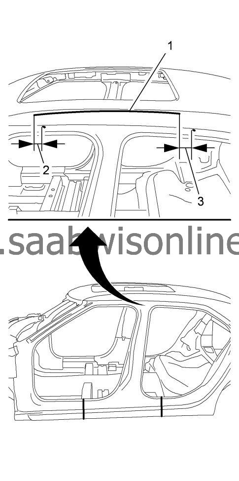
|
|||||||
| 6. |
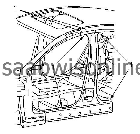
Create cut line
10 mm (0.4 in)
on the upper front side panel (1).
|
|
| 7. |
Cut 80 mm in front of the luggage carrier side rail front support reinforcement and 150 mm in front of the luggage carrier side rail rear support reinforcement.
|
|
| 8. |
Cut out the body lock pillar outer panel roughly.
|
|
| 9. |
Locate and drill out all of the necessary factory welds.
|
|
| 10. |
Create cut lines on the body lock pillar outer panel reinforcement (1). 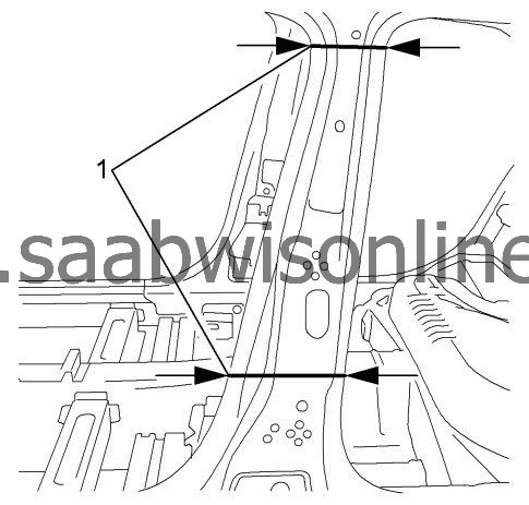
|
|||||||
| 11. |
Cut out the body lock pillar outer panel reinforcement roughly.
|
|
| 12. |
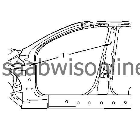
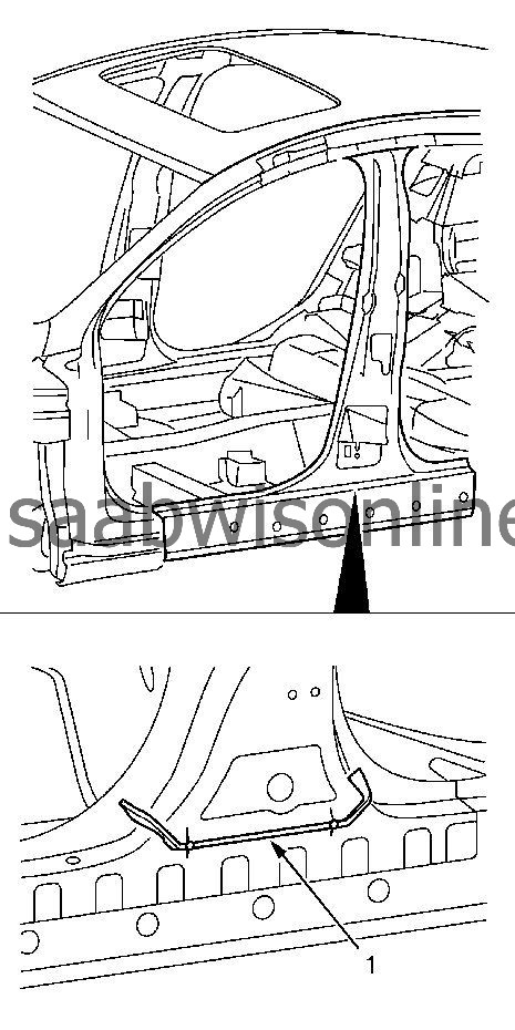
Drill out the necessary factory welds (1). 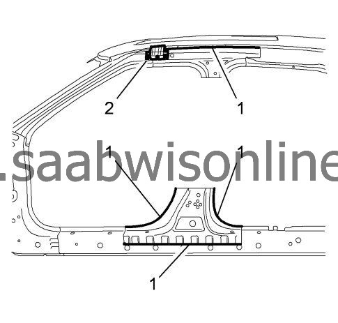
|
|||||||
| 13. |
Remove the luggage carrier side rail front support reinforcement (2). Refer to
Luggage Carrier Side Rail Front Support Reinforcement Replacement
.
|
|||||||
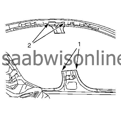
| 14. |
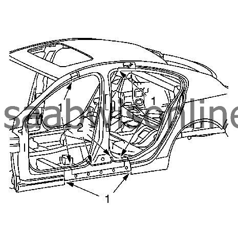
Drill out the necessary factory welds (1) on the center pillar inner panel lower reinforcement.
|
|
| 15. |
Drill out the necessary factory welds (2) on the center pillar inner panel.
|
|
| 16. |
Remove the damaged body lock pillar outer panel reinforcement.
|
|
| Installation Procedure |
| 1. |
Create cut lines on the body lock pillar outer panel (1). 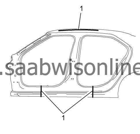
|
|||||||
| 2. |
Cut the body lock pillar outer panel in corresponding locations to fit the original panel. The sectioning joint should be trimmed to allow min. 1 times the metal thickness at the sectioning joint.
|
|
| 3. |
Prepare new body lock pillar outer panel in the area (1).
1 x slots (5 x 18 mm / 0.2 x 0.7 in) |
|
| 4. |
Prepare new body center pillar inner panel in the area (1).
14 x slots (8 x 24 mm / 0.3 x 0.9 in) 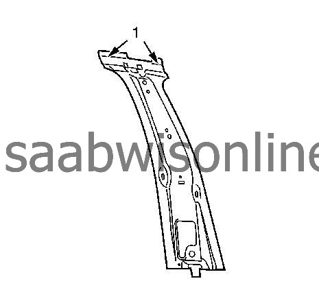
|
|
| 5. |
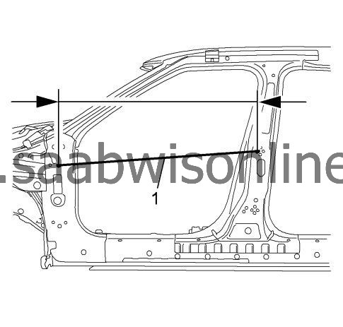
Position and measure (1) from the front hinge pillar body to the center pillar inner panel
1191 mm (48.9 in)
on to the vehicle.
|
|
| 6. |
Verify the fit of the center pillar inner panel.
|
|
| 7. |
Clamp the center pillar inner panel into position.
|
|
| 8. |
Spot weld the center pillar inner panel (1) accordingly. 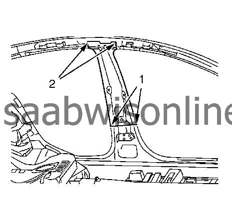
|
|||||||
| 9. |
MIG-braze the center pillar inner panel (2).
|
|
| 10. |
Grind MIG brazed seams.
|
|
| 11. |
Prepare new body lock pillar outer panel reinforcement in the area (1).
Drill out the necessary slots. 9 x slots (8 x 24 mm / 0.3 x 0.9 in) 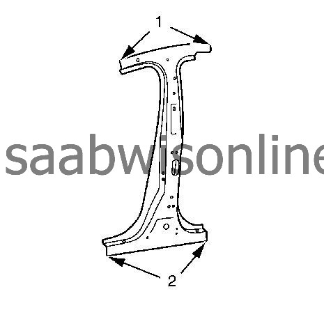
|
|
| 12. |
Prepare new body lock pillar outer panel reinforcement in the area (2).
9 x slots (8 x 24 mm / 0.3 x 0.9 in) |
|
| 13. |
Clean and prepare the attaching surfaces for welding.
|
|
| 14. |
Apply bodywork repair through structural adhesive to body (1). Refer to
Structural Adhesive Body Repairs
.
|
|
| 15. |
Position and measure (1) from the front hinge pillar body to the rear hinge pillar body
1090 mm (43 in)
on to the vehicle.
|
|
| 16. |
Verify the fit of the body lock pillar outer panel reinforcement.
|
|
| 17. |
Clamp the body lock pillar outer panel reinforcement into position.
|
|
| 18. |
Spot tack-weld the body lock pillar outer panel reinforcement (1). 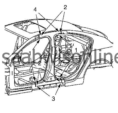
|
|||||||
| 19. |
MIG-braze the body lock pillar outer panel reinforcement (2).
|
|
| 20. |
MIG-braze full seam interrupted 9 times
30 mm (1.2 in)
the body lock pillar outer panel reinforcement (3).
|
|
| 21. |
MIG-braze full seam interrupted 5 times
30 mm (1.2 in)
the body lock pillar outer panel reinforcement (4).
|
|
| 22. |
Grind MIG-brazed seams.
|
|
| 23. |
Install the sound deadener (1).
|
|
| 24. |
Install the luggage carrier side rail front support reinforcement. Refer to
Luggage Carrier Side Rail Front Support Reinforcement Replacement
.
|
|
| 25. |
Clean and prepare the attaching surfaces for welding.
|
|
| 26. |
Apply bodywork repair through structural adhesive to body (1). Refer to
Structural Adhesive Body Repairs
.
|
|
| 27. |
Apply 1K-Adhesive bead on the sound deadener (2). Refer to
Chemical Products
.
|
|
| 28. |
Position the body lock pillar outer panel on the vehicle.
|
|
| 29. |
Verify the fit of the roof outer panel.
|
|
| 30. |
Clamp the body lock pillar outer panel into position.
|
|
| 31. |
Spot weld the body lock pillar outer panel (1) accordingly. 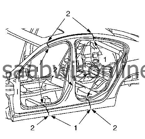
|
|||||||
| 32. |
MIG-braze the body lock pillar outer panel (2).
|
|
| 33. |
Grind MIG brazed seams.
|
|
| 34. |
Apply the sealers and anti-corrosion materials to the repair area, as necessary. Refer to
Anti-Corrosion Treatment and Repair (Base)
Anti-Corrosion Treatment and Repair (Corrosion Protection)
.
|
|
| 35. |
Connect the negative battery cable. Refer to
Battery Negative Cable Disconnection and Connection
.
|
|
| 36. |
Enable the SIR system. Refer to
SIR Disabling and Enabling
.
|
|
