PRE-RELEASE
Drivetrain and Front Suspension Frame Front Crossmember Replacement (GNB)
| Drivetrain and Front Suspension Frame Front Crossmember Replacement (GNB) |
Special Tools
CH-49289 Centering Adapter, Subframe BodyFor equivalent regional tools, refer to Special Tools .
| Removal Procedure |
| 1. |
Detach the steering intermediate shaft from the steering gear. Refer to
Intermediate Steering Shaft Replacement
.
|
|
| 2. |
Remove the front wheels. Refer to
Tire and Wheel Removal and Installation
.
|
|
| 3. |
Remove the undertray.
|
|
| 4. |
Remove the front bumper fascia center support. Refer to
Front Bumper Fascia Center Support Bracket Replacement
.
|
|
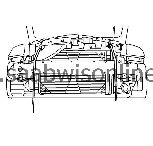
| 5. |
Tie the radiator, air conditioning condenser, and fan module assembly to the upper radiator support to keep the assembly with the vehicle when the frame is lowered.
|
|
| 6. |
Remove exhaust front pipe. Refer to
Exhaust Front Pipe Replacement (LDK/A20NHT, LAU/A28NER)
Exhaust Front Pipe Replacement (LBS/A20DTH)
.
|
|
| 7. |
XWD: Remove propeller shaft. Refer to
Propeller Shaft Replacement
.
|
|
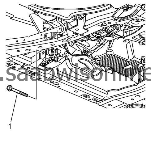
| 8. |
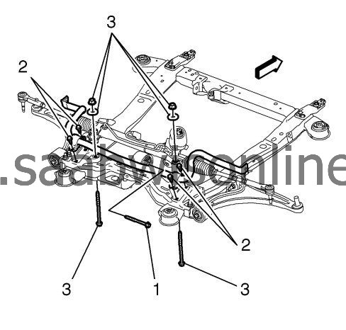
Remove the front transmission mount-to-frame bolt (1).
|
|
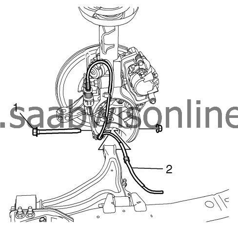
| 9. |
Remove the fastener and separate the lower control arm from the steering knuckle (1). Refer to
Lower Control Arm Replacement (GNA)
Lower Control Arm Replacement (GNB)
.
|
|
| 10. |
Remove the electrical harness and the power steering cooler line from the clips in the frame (2).
|
|
| 11. |
Remove the stabilizer shaft link from stabilizer shaft. Refer to
Stabilizer Shaft Link Replacement (GNA)
Stabilizer Shaft Link Replacement (GNB)
.
|
|
| 12. |
Remove the steering gear inlet and outlet hose and plug the hoses. Refer to
Steering Gear Replacement
.
|
|
| 13. |
If equipped with variable effort steering, disconnect electrical connectors from the steering gear.
|
|
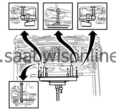
| 14. |
Raise
CH-49289
centering adapter until contact with the location pins in lower position. Then move the location pins into the centering holes of the body. If this fits, no alignment is needed. Then lower the location pins. See instructions for
CH-49289
centering adapter. Refer to
Engine Support Fixture (Rear Side)
Engine Support Fixture (Front Side)
Engine Support Fixture (Mounting Engine/Transmission)
Engine Support Fixture (Centering Adapter)
Engine Support Fixture (Engine Bridge, Retainer Frame)
.
|
|
| 15. |
Carefully raise the
CH-49289
centering adapter tool until the frame contacts.
|
|
| 16. |
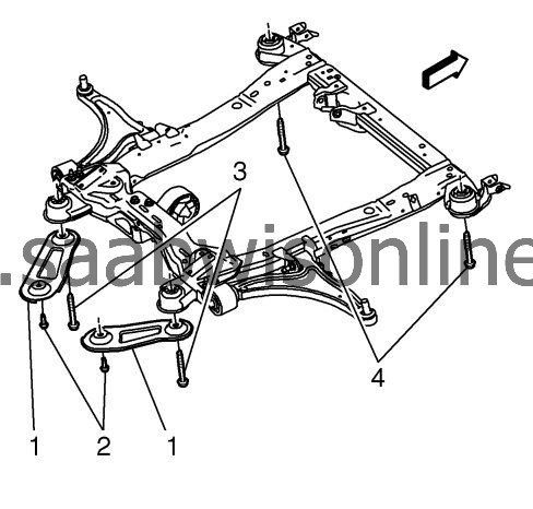
Remove the reinforcement bolts (2). DISCARD the bolts.
|
|
| 17. |
Remove the rear frame to body bolts (3).
|
|
| 18. |
Remove the reinforcement (1) from the vehicle.
|
|
| 19. |
Remove the front frame-to-body bolts (4).
|
|
| 20. |
Remove the rear transmission mount-to-frame bolt (1).
|
|
| 21. |
Carefully lower the
CH-49289
centering adapter tool in order to separate the frame from the body approximately 50 mm.
|
|
| 22. |
Carefully lower the
CH-49289
centering adapter tool in order to separate the frame from the body.
|
|
| 23. |
Remove the following components if replacing the frame:
|
|
| • |
The steering gear. Refer to
Steering Gear Replacement
.
|
| • |
The lower control arms. Refer to
Lower Control Arm Replacement (GNA)
Lower Control Arm Replacement (GNB)
.
|
| • |
The stabilizer shaft. Refer to
Stabilizer Shaft Replacement
.
|
| • |
The radiator support brackets
|
| Installation Procedure |
| 1. |
Install the following components if replacing the frame:
|
|
| • |
The steering gear. Refer to
Steering Gear Replacement
.
|
| • |
The lower control arms. Refer to
Lower Control Arm Replacement (GNA)
Lower Control Arm Replacement (GNB)
.
|
| • |
The stabilizer shaft. Refer to
Stabilizer Shaft Replacement
.
|
| • |
The radiator support brackets
|
| 2. |
Raise
CH-49289
centering adapter until contact. Then move the location pins into the centering holes of the body with the location pins in upper position. See instructions for
CH-49289
centering adapter. Refer to
Engine Support Fixture (Rear Side)
Engine Support Fixture (Front Side)
Engine Support Fixture (Mounting Engine/Transmission)
Engine Support Fixture (Centering Adapter)
Engine Support Fixture (Engine Bridge, Retainer Frame)
.
|
|
| 3. |
Carefully raise the
CH-49289
centering adapter. The frame shall be approximately 50 mm from the body in order to get access with the torque wrench.
|
|
| 4. |
Install the electrical harness and the power steering cooler line to the clips in the frame (2).
|
|
| 5. |
Connect the lower control arm to the steering knuckle and install the fastener (1). Refer to
Lower Control Arm Replacement (GNA)
Lower Control Arm Replacement (GNB)
.
|
|
| 6. |
Carefully raise the
CH-49289
centering adapter tool in order to attach the frame to the body.
|
|
| 7. |
Loosely install the front frame-to-body bolts (4).
|
|
| 8. |
Position the reinforcement (1) to the vehicle.
|
|
| 9. |
Loosely install the rear frame to body bolts (3).
|
|
| 10. |
Loosely install the reinforcement bolts (2).
|
|
| 11. |
Carefully lower the
CH-49289
centering adapter tool from the frame.
Refer to Fastener Caution . |
|
| 12. |
Install the rear transmission mount-to-frame bolt and tighten to
100 Nm (74 lb ft)
.
|
|
| 13. |
Tighten the frame-to-body reinforcement bolts (2) to
60 Nm (44 lb ft) +45°
.
|
|
| 14. |
Tighten the frame-to-body bolts to
160 Nm (118 lb ft)
.
|
|
| 15. |
Install the front transmission mount-to-frame bolt (1) and tighten to
100 Nm (74 lb ft)
.
|
|
| 16. |
If equipped with variable effort steering, connect electrical connector to steering gear.
|
|
| 17. |
Install the steering gear inlet and outlet hose. Refer to
Steering Gear Replacement
.
|
|
| 18. |
Install the stabilizer shaft link to stabilizer shaft. Refer to
Stabilizer Shaft Link Replacement (GNA)
Stabilizer Shaft Link Replacement (GNB)
.
|
|
| 19. |
XWD: Install propeller shaft. Refer to
Propeller Shaft Replacement
.
|
|
| 20. |
Install the exhaust front pipe. Refer to
Exhaust Front Pipe Replacement (LDK/A20NHT, LAU/A28NER)
Exhaust Front Pipe Replacement (LBS/A20DTH)
.
|
|
| 21. |
Untie the radiator, air conditioning condenser, and fan module assembly from the upper radiator support.
|
|
| 22. |
Install the steering intermediate shaft to the steering gear. Refer to
Intermediate Steering Shaft Replacement
.
|
|
| 23. |
Install the front bumper fascia center support. Refer to
Front Bumper Fascia Center Support Bracket Replacement
.
|
|
| 24. |
Install the undertray.
|
|
| 25. |
Install the front wheels. Refer to
Tire and Wheel Removal and Installation
.
|
|
| 26. |
Lower the vehicle.
|
|
| 27. |
If replacing the frame, check wheel alignment. Refer to
Wheel Alignment Specifications
.
|
|
