Welded, Brazed, and Riveted Joint Specifications
|
|
Welded, Brazed, and Riveted Joint Specifications
|
|
Note
|
|
Please also pay attention to body repair using structural adhesive, equipment recommendations for resistance spot welding machines and equipment recommendation for MIG brazing.
|
Significant changes to the vehicle design lead to new joining techniques in bodywork production.
Significant changes in the manufacturing process generally result from:
|
•
|
The use of pre-painted sheet metal to increase corrosion protection.
|
|
•
|
The use of higher strength and highest strength sheet metal to increase body rigidity/impact safety while at the same time reducing vehicle weight.
|
Joining techniques recently introduced in bodywork production include:
|
•
|
Laser-welded vehicle roof
|
|
•
|
Gas-shielded MIG brazing
|
These new joining methods must be applied/adapted to the special requirements of service based on the new material quality and joining techniques so as to ensure professional bodywork repair.
 Warning
|
|
The specifications named below must be followed. Failiure to do so could lead to component damage, such as corrosion or structural damage at the repair area.
|
|
|
|
|
|
|
•
|
Before the start of work, a test weld/brazing is to be carried out on the area to be repaired (similar to a sample paint spray test). This is done by subjecting a sample of the relevant panel joint to a test weld/brazing and seam check. The sample panel must come from the vehicle to be repaired or be a new part.
|
|
•
|
Structural seams (e.g. butt seam upon part replacement in the area of the front frame) are to be sealed with body sealant after priming. Before installing closure plates, make sure that corrosion protection is applied to areas such as the rear plate and weld seams in cavities. Inaccessible cavities are to be sealed as well. Cavity sealing after painting is mandatory.
|
|
•
|
The configuration of the welded and brazed joints for metal service parts sometimes differs from the seam configuration or joint specification used in production due to the different joining methods and joining order. For example, slots must be made in certain service parts or body sections in order to create the joint. For these such cases, the service literature explicitly specifies the configuration of the joint.
|
|
•
|
For certain joining methods or seam geometries, it may be necessary to attach a reinforcing plate at the location of the joint. This plate serves to ensure a high-quality connection that has the same structural properties as a new part. The reinforcing sheet metal is to be taken from the new part remnant or from the component of the sheet metal to be repaired. The service instructions provide information on the configuration and connection to be used for the reinforcing sheet metal. In order to prevent structural breaches, the corners and edges of the reinforcing pate are to be deburred and bevelled.
|
|
•
|
For structural seams (e.g. butt seams upon part replacement at the front frame), the deck/root seam must not be ground or smoothed. Reason: structural breach of the component upon grinding, notching or heat, uncontrolled reduction in metal thickness.
|
|
•
|
Specific welding/brazing parameters are to be set for the individual seam areas based on equipment version. This information is to be taken from the equipment manufacturer documentation.
|
|
•
|
Should a resistance spot welding spot require special settings, such is indicated by entering SPP in field 5. Settings can be found in the parameter lists of the recommended equipment manufacturers. Recommended manufacturers can be found in the newsletter.
|
|
•
|
No spot weld primer is to be used at joints when using gas-shielded welding methods, such as MAG welding and MIG brazing. Reason: reduction of seam quality through gas emission, causing pore formation, which reduces the strength of the seam.
|
|
•
|
Rivets are only to be used on metal body parts in combination with the adhesive sealing system. Only waterproof, stainless steel rivets are allowed to be used. Use of aluminium rivets instead of steel is not permitted due to corrosion and insufficient strength. For further information, see the service instructions.
|
|
1.
|
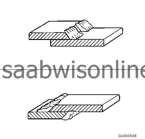
Resistance spot welding
A constant, high welding current and contact pressure of the welding pliers is required to attach high-strength, coated sheet metal. Satisfactory spot quality cannot be expected with conventional spot welding machines and welding pliers due to the differing power and compress air supplies available at various dealers.
The latest generation of spot welding machines (e.g. mid-frequency spot welding machines) have great advantages in this respect. The spot welds produced by these spot welding machines are of the same quality as those specified by the manufacturer for bodywork production.
|
|
2.
|
MAG (Metal Active Gas) welding
The MAG welding method has many applications when it comes to joining sheet metal, especially for uncoated and low alloy sheet metal.
MAG welding properties include:
|
|
|
•
|
Seam temperature of approx. 1500°C (2732°F)
|
|
|
•
|
The outgassing of the zinc coating can lead to instable arcs and pores in the weld seam
|
|
|
•
|
Base material is superficially fused
|
|
|
•
|
Structural change in the base material in the area of the weld seam
Due to the particularities of the MAG-welding process, the connection area can have more or less pronounced weaknesses. These depend primarily on the type of coating and its thickness, as well as on the physical properties of the base material. For this reason it is essential to apply the MAG-welding process only in the areas specified in the service instruction.
|
Note
|
|
The exact mode of procedure and areas of application can be taken from the appropriate operations on TIS.
|
|
|
3.
|
MIG (Metal Inert Gas) brazing
MAG brazing offers a number of advantages when joining high-strength, coated sheet metal.
|
|
|
•
|
Minimal heating seam temperature approx. 950°C (1742°F)
|
|
|
•
|
Minimal zinc melting loss
|
|
|
•
|
Seam is protected against corrosion
|
|
|
•
|
Base material is not superficially fused
|
|
|
•
|
No structural change in the base material
|
|
4.
|
Rivets
The riveting technique is suitable as an additional joining technique in bodywork repair as an alternative to resistance spot welding. Rivets are always used in combination with the adhesive sealing system.
Use only waterproof steel rivets for repairing metal body parts.
|
|
Callout
|
Description
|
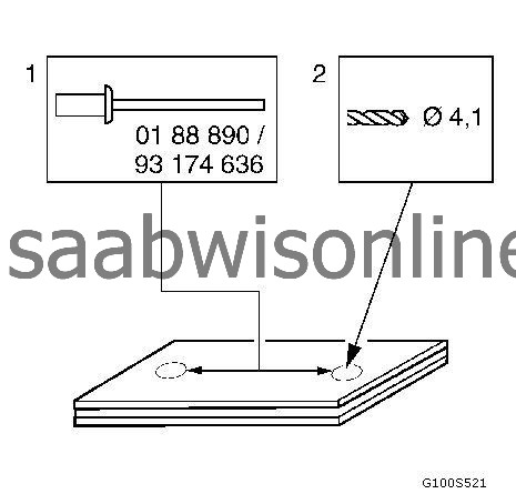
1
|
Steel rivet, e.g.: part no. 93 174 636
Rivet head length:
12 mm (0.5 in)
|
2
|
Bore diameter:
Ø 4.1 mm (0.2 in)
|
|
Note
|
|
MAG welding must comply with guideline QT 001131.
|
|
•
|
MIG brazing must comply with guideline GME7834.
|
|
•
|
Spot welding operations must comply with guideline QT 001130.
|
|
•
|
The most recently updated version of the guidelines is to be applied.
|
The guidelines can be requested from the following address (subject to a fee):
|
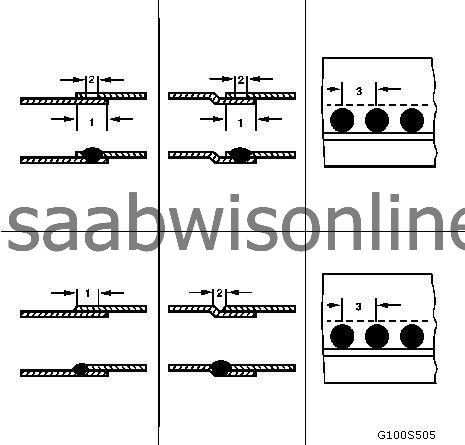
Callout
|
Description
|
1
|
Resistance Spot Welding
|
2
|
Plug Spot Welding
|
3
|
I
|
Overlapped
|
II
|
Offset
|
1
|
10-20 mm (depending on plug) (0.4-0.8 in)
|
2
|
6 mm for sheet metal up to 1.0 mm (0.04 in)
8 mm for sheet metal up to 2.0 mm (0.08 in)
|
3
|
30-40 mm plug weld spacing (1.2-1.6 in)
|
Quilting Seam Spot Welding/Spot Brazing
|
I
|
Overlapped
|
II
|
Offset
|
1
|
10-14 mm (0.4-0.6 in)
|
2
|
3-5 mm (0.1-0.2 in)
|
3
|
30-40 mm (1.2-1.6 in)
|
|
Callout
|
Description
|
4
|
I
|
Overlapped
|
II
|
Offset
|
1
|
At least 15-20 mm (depending on slot size) (0.6-0.8 in)
|
2
|
See 4.2 Slot Sizes
|
3
|
Spacing and number of slots (see specification in service instruction)
|
|
Callout
|
Description
|
4
|
I
|
5x18 mm slot (sheet metal thickness up to 0.8 mm) (0.03 in)
6x20 mm slot (sheet metal thickness 0.8-1.2 mm) (0.03-0.05 in)
8x24 mm slot (sheet metal thickness over 1.2 mm) (0.05 in)
|
II
|
6x8x20 mm slot with pre-drilled spot welds (0.8-1.2 mm sheet metal) (0.03-0.05 in)
|
|
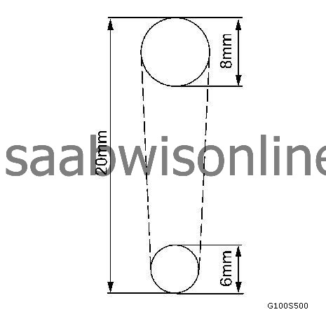
Callout
|
Description
|
5
|
I
|
Butt-Welded Joint
|
II
|
Overlapped
|
III
|
Offset
|
|
Callout
|
Description
|
6
|
I
|
Overlapped - One Side
|
II
|
Overlapped - Both Sides
|
|
Rivets/Resistance Spot Welding Together with Structural Adhesive
|
|
Callout
|
Description
|
7
|
I
|
Flange length (1) <= 50 mm (<=2 in)
Quantity: 1
in centre of flange
|
II
|
Flange length (1) 50 mm <= 150 mm (2 in <= 6 in)
Quantity: 2
Distance (2) even distributed from the centre of the flange
Distance to edge (3) max. 20 mm (0.8 in)
|
III
|
Flange length (1) > 150 mm (> 6 in)
Quantity based on component
Spacing (2) 150 mm (6 in)
Distance to edge (3) max. 20 mm (0.8 in)
|
Rivet Lengths and Areas of Application
|
Rivet Length
|
Rivet Diameter
|
Clamping Area (sum total of sheet thicknesses to be joined together)
|
Part No.
|
Catalogue No.
|
8 mm (0.3 in)
|
4 mm (0.2 in)
|
1.5-3.0 mm (0.06-0.1 in)
|
9318403
|
1 84 983
|
9.5 mm (0.4 in)
|
4 mm (0.2 in)
|
3.0-5.0 mm (0.1-0.2 in)
|
9318403
|
1 84 984
|
12 mm (0.5 in)
|
4 mm (0.2 in)
|
6.5-8.5 mm (0.25-0.33 in)
|
9317463
|
1 88 890
|
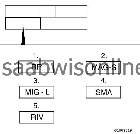
Explanation of Designations for Joining Techniques
|
Abbreviation
|
Description
|
RP
|
Resistance Spot Welding
|
SG
|
Gas-Shielded Arc Welding
|
MSG
|
Gas Metal Arc Welding
|
MAB - S
|
MAG Welding (Steel-based welding wire material)
|
MIG - L
|
MIG Brazing (Copper-based brazing wire material)
|
SMA
|
Structural Metal Adhesive
|
RIV
|
Use of Waterproof Steel Rivets
|
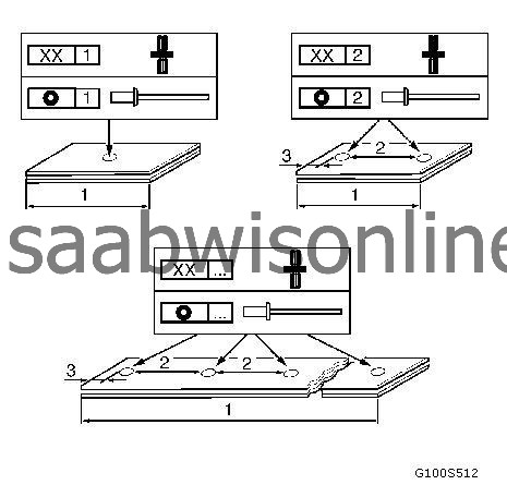
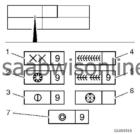
The symbols are divided into the following information specifications:
|
Callout
|
Description
|
1
|
Seam Form Field
|
2
|
Seam Quantity Field
|
3
|
Seam Length Field
|
4
|
Welding Method Field
|
5
|
Welding/Brazing Wire Material or SPP
|
|
Callout
|
Description
|
1
|
Resistance spot welding (Qty: 9)
|
2
|
Plug spot welding, gas-shielded arc welding (Qty: 9) slot brazing, gas-shielded brazing (Qty: 9)
|
3
|
Quilting seam spot welding/spot brazing with sheet metal overlap, gas-shielded arc welding and gas-shielded brazing (Qty: 9)
|
4
|
Full seam, gas-shielded arc welding and gas-shielded brazing
|
5
|
Full seam, interrupted, gas-shielded arc welding (Qty: 9)
|
6
|
Structural metal adhesive (adhesive, part no. 93 160 535)
|
7
|
Rivets (steel rivets, part no. 93 174 636, Qty: 9)
|
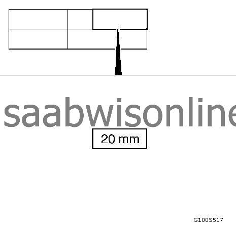
Example for seam length:
|
1.
|
Seam length is always specified with measurement and unit (mm).
|
|
2.
|
The minimum seam length (lower limit) for applying a full seam is always to be set to 15 mm (0.6 in).
|
|
3.
|
The following applies to plug welds:
|
|
|
3.1.
|
Seam length is not applicable, i.e. the seam length is always matches the shape of the round hole or slot.
|
|
|
3.2.
|
The hole must be completely filled, i.e. the seam must completely cover the hole.
|
|
|
3.3.
|
In the event of top bead depression, rewelding is required (thickness of the seam).
|
|
Callout
|
Description
|
1
|
Resistance Spot Welding
|
2
|
MIG/MAG Welding
|
3
|
Gas-shielded MIG brazing
|
4
|
Structural Metal Adhesive
|
5
|
Rivets
|
|
Welding/Brazing Wire Material or Special Programs for Resistance Spot Welding Field
|
|
1.
|
|
Note
|
|
The welding/brazing wire material must be specified. Welding/brazing wire material is to be selected based on the quality of the sheet metal at the area to be repaired.
|
MAG welding
G3Si1, 1 mm (0.04 in) wire diameter, for low alloy steel. Shielding gas: argon/CO2 mixture (e.g. 92% Ar / 8% CO2).
|
|
2.
|
MIG brazing
SG - CuSi3, 1 mm (0,04 in) wire diameter (part no. 93 180 983). Shielding gas: Argon (quality min. 4.6).
|
|
3.
|
Resistance spot welding
Special parameter program (SPP) or pre spot operation (PSO) for resistance spot welding.
|
|
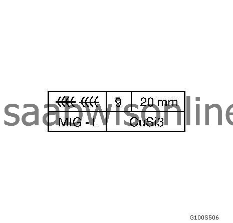
•
|
Full seam, interrupted, 9 seams
|
|
•
|
Seam length 20 mm, MIG (0.8 in)
|
|
•
|
Gas-shielded brazing, CuSi3 wire
|
|
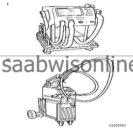
Commercially Available Equipment
|
|
1.
|
|
Note
|
|
The maximum electrode arm length (plier separation) for resistance spot-welding when using X or scissor pliers is 400 mm (15.8 in).
|
Resistance spot welding machine.
|
|
2.
|
Gas-shielded welding equipment for:
|
