PRE-RELEASE
Cylinder Head Disassemble
| Cylinder Head Disassemble |
Special Tools
| • |
EN-849
Assembly Tray
|
|
| • |
EN-6167
Fixing Tool
|
|
| • |
EN-6171
Release Tool
|
|
| • |
EN-6215
Mounting Equipment
|
|
| • |
EN-840
Remover
|
|
For equivalent regional tools, refer to Special Tools .
| 1. |
Fit the EN-6215-5 side mounts (1) for the EN-6215-4 assembly fixture. 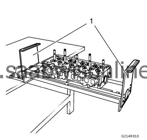
|
|||||||
| 2. |
Install
EN-6215-4
assembly device (1).
|
|
| 3. |
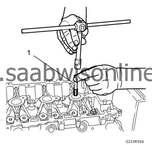
The spark plug threads must be cleaned of combustion residues to ensure that the counterhold can be attached correctly. Insert tap M14 x 1.25 (1) in the spark plug thread and screw in evenly.
|
|
| 4. |
Turn the cylinder head baseplate.
|
|
| 5. |
Install the counter holder. |
|||||||
| 6. |
Counter holder type A (1). 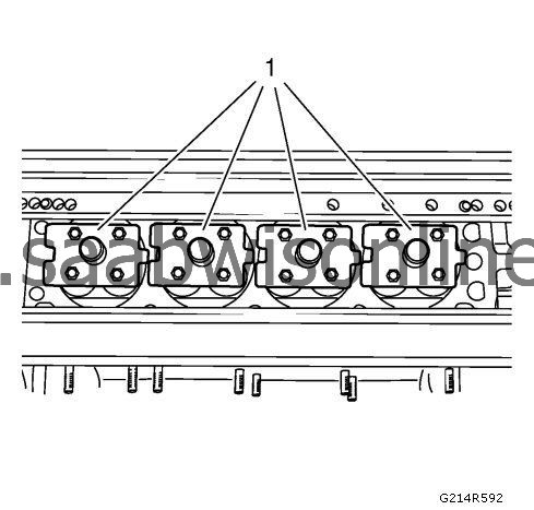
|
|||||||
| 7. |
Counter holder type B (1). 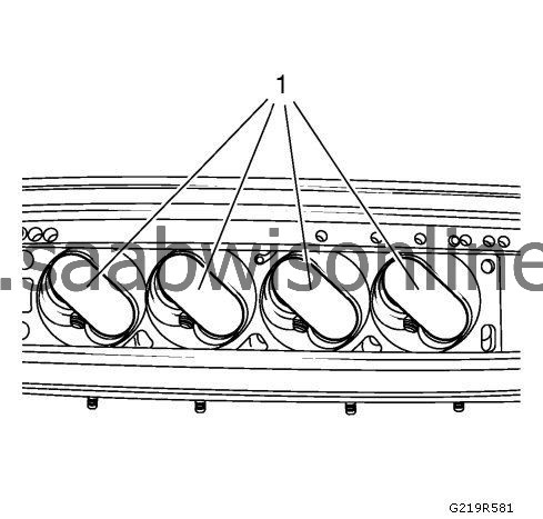
|
|||||||
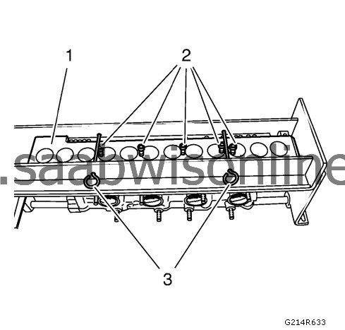
| 8. |
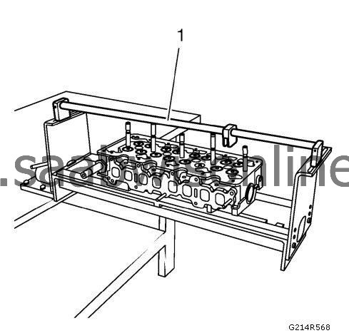
Install the
EN-6167
fixing tool (1). Attach the
EN-6215-3
mounting equipment (3) with safety lock pins. Install the fixing bolts (2). Turn the cylinder head baseplate again.
|
|
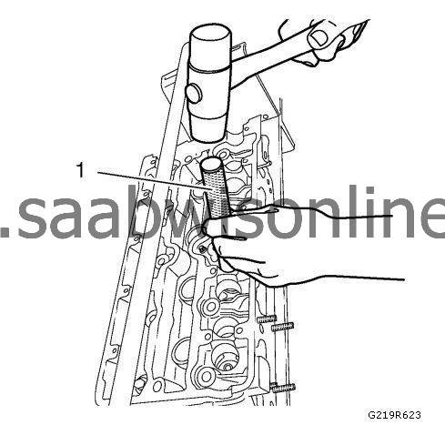
| 9. |
To ensure that no special tools are damaged during the disassembly of the valve wedges, the valve retainers are to be released with the
EN-6171
release tool (1). Put the
EN-6171
release tool on the valve retainers and with a short impact of a rubber hammer all valve retainers will loose (setting behavior).
|
|
| 10. |
Push the depressing tool (1) down with lever until the valve spring cap is released. Remove valve cotters. 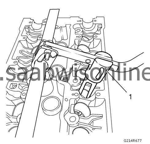
|
|||||||
| 11. |
Remove the upper valve spring caps and valve springs and place them in order on the
EN-849
assembly tray.
Release the valve stem sealings by turning with EN-840 remover (1) and remove from the valve guides. 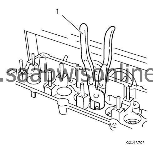
|
|
| 12. |
Remove the lower valve spring caps or valve rotators from the cylinder head and also place on the
EN-849
valve box (1).
|
|
| 13. |
Remove lever tool.
|
|
| 14. |
Turn the cylinder head baseplate. Remove wooden board
EN-6215
mounting equipment and counter holder if attached.
|
|
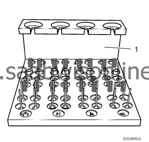
| 15. |
Remove all valves in sequence and place on
EN-849
assembly tray (1) in order.
|
|
