Cylinder Head Cleaning and Inspection (LDK, LHU)
|
|
Cylinder Head Cleaning and Inspection (LDK, LHU)
|
Special Tools
|
•
|
EN-28410
Gasket Remover
|
|
•
|
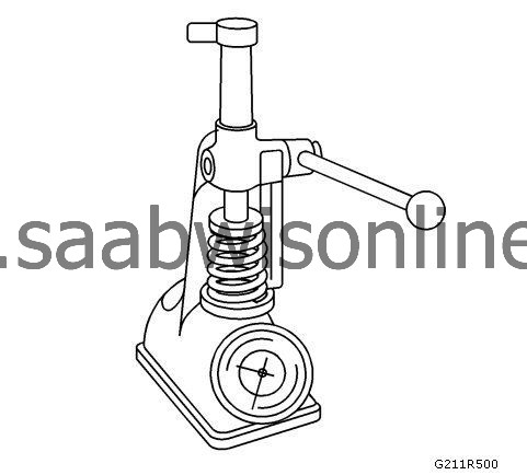
J 7872
Magnetic Base Dial Indicator
|
|
•
|
J 22738-B
Valve Spring Tester
|
For equivalent regional tools, refer to
Special Tools (LDK, LHU)
.
|
Valve Cleaning and Inspection
|
|
1.
|
|
Note
|
|
Do not use a wire brush on any part of the valve stem.
|
|
Note
|
|
Do not grind or condition the intake valve. If the intake valve is out of specification, replace the valve.
|
Clean the valves of carbon, oil and varnish. Use a soft bristle wire brush to clean any carbon build-up from the valve head. Varnish can be removed by soaking in Parts Immersion Solvent. Refer to
Adhesives, Fluids, Lubricants, and Sealers (LDK, LHU)
.
|
|
2.
|
Clean the valve guides.
|
|
3.
|
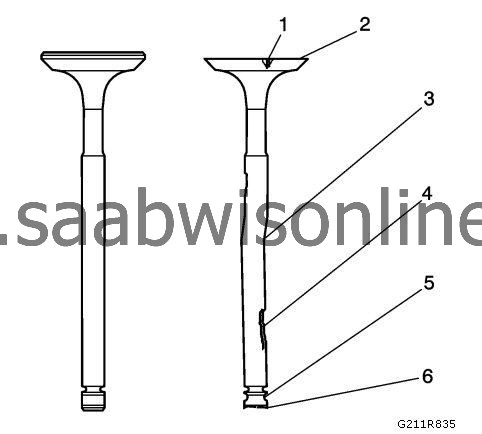
Inspect the valve stem for pitting or wear (4).
|
|
4.
|
Inspect the valve key groove for chipping or wear (5). Replace the valve if chipped or worn.
|
|
5.
|
Inspect the valve face for burning or cracking (1). If pieces are broken off, inspect the corresponding piston and cylinder head area for damage.
|
|
6.
|
Inspect the valve stem for burrs and scratches. Burrs and minor scratches may be removed with an oil stone.
|
|
7.
|
Check that the valve stem is straight (3) and that the valve head is not bent or damaged using V blocks. Bent or damaged valves must be replaced.
|
|
8.
|
Clean the deposits from the valve face. Inspect the valve face for grooving.
|
|
9.
|
Replace the valve if the face is grooved. Valve faces cannot be machined. If worn, or damaged, the valves must be replaced.
|
|
10.
|
Replace the valve if the valve head O.D. and chamfer (2) is worn or out of specification. Refer to
Valve and Seat Grinding
.
|
|
11.
|
The valves may be lightly lapped to the valve seats.
|
|
12.
|
Replace the valve if the valve tip (6) is worn.
|
|
13.
|
If no apparent wear, pitting, grooving, or distortion is present, perform the valve measurement and reconditioning procedure to verify valve specification. Refer to
Valve and Seat Grinding
.
|
|
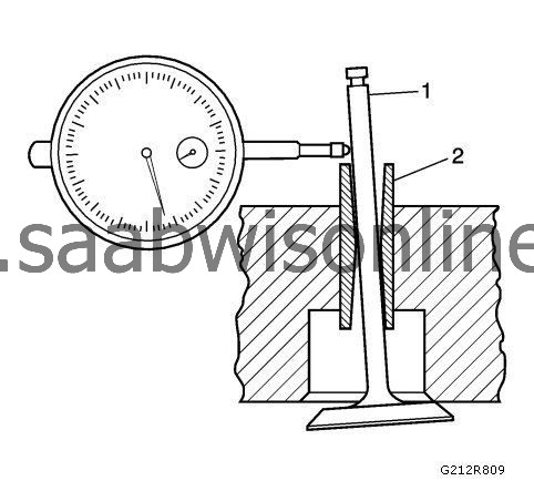
1.
|
Measure the valve stem (1)-to-guide (2) clearance. Excessive valve stem-to-guide clearance may cause an excessive oil consumption and may also cause a valve to break. Insufficient clearance will result in noisy and sticky functioning of the valve and will disturb the engine assembly smoothness.
|
|
2.
|
Clamp the
J 7872
indicator to the cylinder head at the camshaft cover rail.
|
|
3.
|
Locate the dial indicator so that the movement of the valve stem from side to side, crossways to the cylinder head, will cause a direct movement of the indicator stem. The dial indicator stem must contact the side of the valve stem just above the valve guide.
|
|
4.
|
Drop the valve head about 0.064 mm (0.0025 in) off the valve seat.
|
|
6.
|
|
Note
|
|
Valve guide wear at the bottom 10 mm (0.390 in) of the valve guide is not significant to normal operation.
|
If the clearance for the valve is greater than specifications and a new standard diameter valve stem will not bring the clearance within specifications, replace the cylinder head.
|
|
Valve Spring Cleaning and Inspection
|
|
1.
|
Clean the valve springs in solvent.
|
|
3.
|
Inspect the valve springs for broken coils or coil ends.
|
|
5.
|
If a low valve spring loading is observed, the valve springs must be replaced. Do not use a shim to increase the spring loading. The use of shims can cause the valve spring to bottom out before the camshaft lobe is at peak lift.
|
|
Valve Rocker Arm Cleaning and Inspection
|
|
1.
|
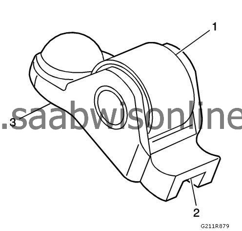
Inspect the camshaft follower roller (1) for the following:
|
|
|
•
|
Excessive scoring and pitting
|
|
|
•
|
Ensure the roller spins freely
|
|
2.
|
Inspect the camshaft follower valve tip area (2).
|
|
3.
|
Inspect the camshaft follower stationary hydraulic lash adjuster (SHLA) pivot area (3).
|
|
4.
|
Replace the camshaft follower or followers as necessary.
|
|
Cylinder Head and Gasket Surface Cleaning and Inspection
|
|
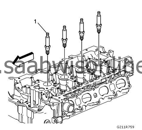
1.
|
Remove the spark plugs (1).
|
|
2.
|
Check the cylinder head gasket and mounting surfaces so that there will be no water leakage, corrosion or loss of compression. If the gasket is damaged, determine the cause by referring to the following possibilities:
|
|
|
•
|
Loose or warped cylinder head
|
|
|
•
|
Missing, off location or not fully seated dowel pins
|
|
|
•
|
Corrosion in the seal area around the coolant passages
|
|
|
•
|
Chips or debris in the cylinder head bolt holes
|
|
|
•
|
Bolt holes in the cylinder block not drilled or tapped deep enough
|
|
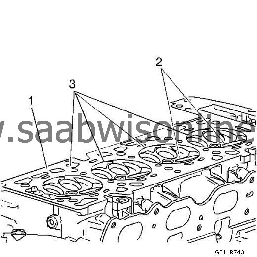
3.
|
Inspect the cylinder head gasket surface.
|
|
|
•
|
The cylinder head may be reused if corrosion is found only outside a 4 mm (0.375 in) band around each combustion chamber (1).
|
|
|
•
|
Replace the cylinder head if the area between the valve seats is cracked (2).
|
|
|
•
|
Replace the cylinder head if corrosion has been found inside a 4 mm (0.375 in) band around each combustion chamber (3).
|
|
4.
|
Clean the cylinder head bolts.
|
|
5.
|
|
Note
|
|
Do not use a wire brush on any gasket sealing surface.
|
Remove the sealant from the rear cap mating surface with
EN-28410
remover. Care must be used to avoid gouging or scraping the sealing surfaces.
|
|
6.
|
Clean the cylinder head bolts. Remove all varnish, soot and carbon to the bare metal.
|
|
7.
|
Clean the valve guides.
|
|
8.
|
Clean the threaded holes. Use a nylon bristle brush.
|
|
9.
|
Clean the remains of the sealer from the plug holes.
|
|
10.
|
Inspect the cylinder head bolts for damaged threads or stretching and damaged heads caused by improper use of tools.
|
|
11.
|
Replace all suspect bolts.
|
|
12.
|
Inspect the cylinder head for cracks. Check between the valve seats and in the exhaust ports.
|
|
13.
|
|
Note
|
|
Do not attempt to weld the cylinder head; replace it.
|
Inspect the cylinder head deck for corrosion, sand inclusions and blow holes.
|
|
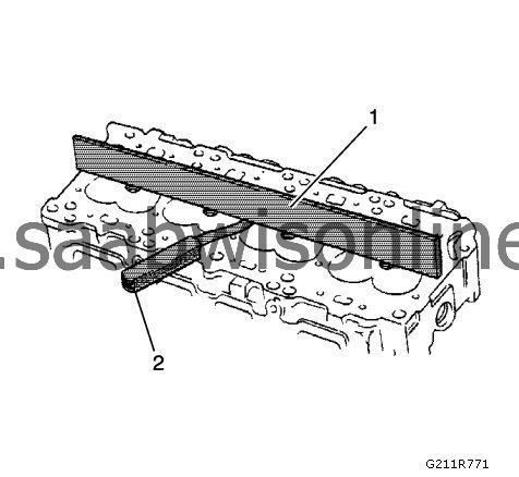
14.
|
Inspect the cylinder head deck surface for flatness using a straight edge (1) and feeler gauge (2). Refer to
Engine Mechanical Specifications (LDK, LHU)
. If the cylinder head is out of specification, replace the cylinder head. Do not machine the cylinder head.
|
|
15.
|
Inspect all the threaded holes for damage. Threads may be reconditioned with thread inserts.
|
|
16.
|
Inspect the sealing surfaces.
|
|
17.
|
Inspect the cylinder head plugs (1).
|
|
18.
|
Clean the sealant from the rear cap mating surface with
EN-28410
remover. Care must be used to avoid gouging or scraping the sealing surfaces.
|
|
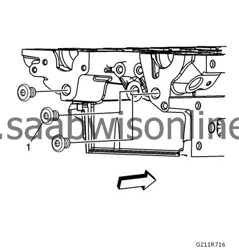
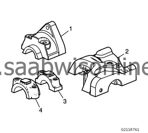
19.
|
Inspect the intake and exhaust camshaft bearing rear caps (1, 2) for damage.
|
|
20.
|
Inspect the rear bearing mating surfaces for damage.
|
|
21.
|
Inspect the remaining bearing caps (3, 4) for damage.
|
|
22.
|
Install the spark plugs (1) and tighten to
20 Nm (15 lb ft)
.
|
|
23.
|
Inspect the lifter bore for damage. Ensure the bore is clean of debris.
|