Intake and Exhaust Camshaft, Bearing Cap, and Lash Adjuster Installation (LDK, LHU)
|
|
Intake and Exhaust Camshaft, Bearing Cap, and Lash Adjuster Installation (LDK, LHU)
|
|
Exhaust Camshaft and Components Installation
|
|
3.
|
|
Note
|
|
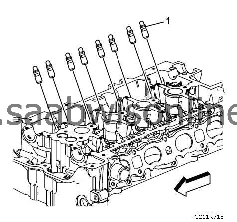
Used roller followers must be returned to the original position on the camshaft. If the camshaft is being replaced, the roller followers actuated by the camshaft must also be replaced.
|
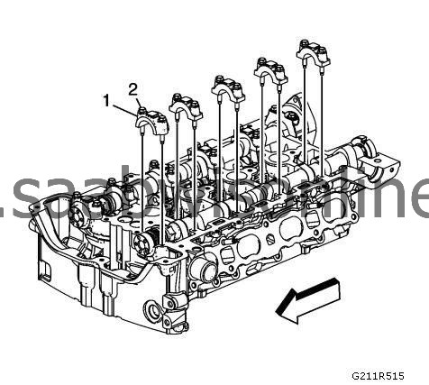
Position the roller followers (1) on the tip of the valve stem and on the lash adjuster. Apply lubricant to the followers, refer to
Adhesives, Fluids, Lubricants, and Sealers (LDK, LHU)
.
|
|
4.
|
|
Note
|
|
The engine is timed top dead center exhaust stroke.
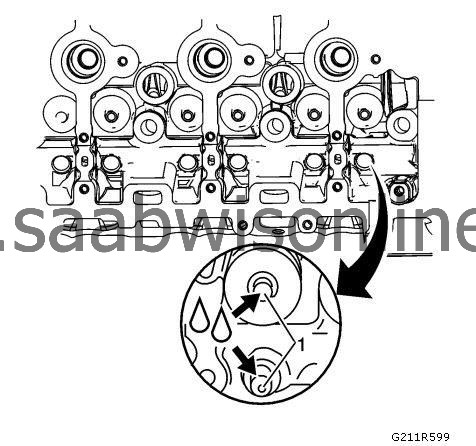
|
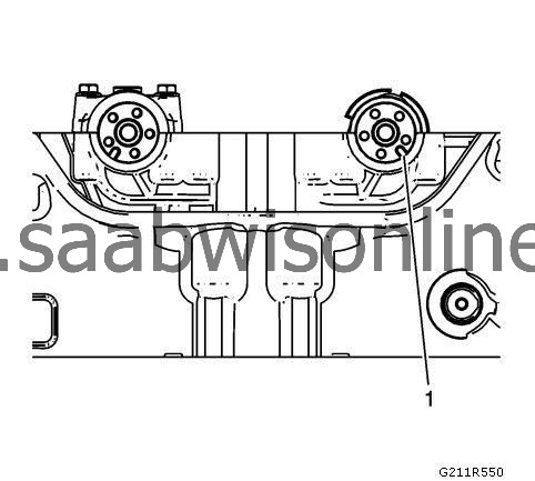
When installing the camshafts, ensure the exhaust camshaft notch is in the 7 o"clock position (1). The number 1 piston should be at top dead center (TDC), crankshaft key at 12 o"clock.
|
|
6.
|
Rotate the oil seal in the groove of the number one camshaft journal so the split line (1) is at approximately the 12 o"clock position before installing the camshaft caps.
|
|
7.
|
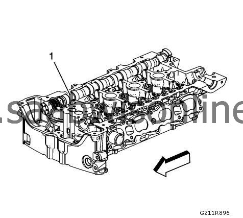
Install the exhaust camshaft with the notch on the front (1) at approximately the 7 o'clock position.
|
|
8.
|
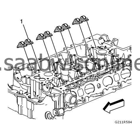
Install the camshaft caps (1) and hand start the camshaft cap bolts (2).
|
|
9.
|
Refer to
Fastener Caution
.
Lubricate and tighten the camshaft cap bolts in increments of 3 turns until they are seated. Tighten the camshaft cap bolts to
10 Nm (89 lb in)
.
|
|
10.
|
|
Note
|
|
It is critical during installation to ensure the bearing rear cap and cylinder head alignment is correct and the mating surfaces are flush.
|
|
•
|
Ensure that all sealing material has been removed from the components, and the sealing surfaces are clean and free of contamination prior to applying the sealer.
|
|
•
|
Install and align the rear cap within 20 minutes of applying the sealer.
|
|
Note
|
|
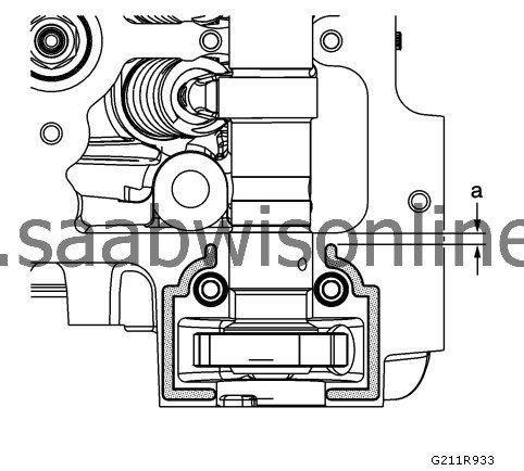
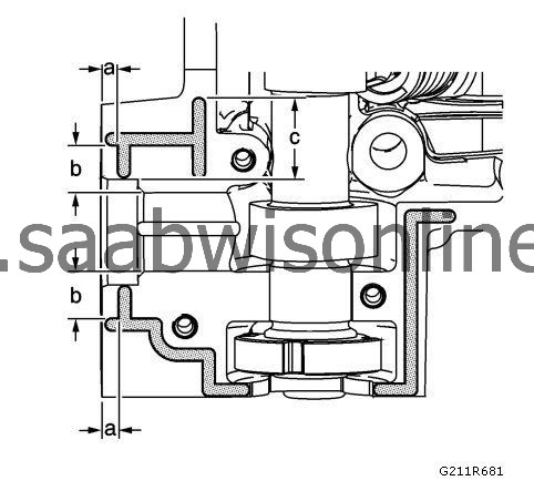
Apply the sealer to all locations centrally locating the bead on the rail. Run bead to within 2.0 mm of the end points, dimension a, as shown. Where the cap ends on the perimeter rail, extend bead approximately 2.0 mm beyond edge of cap.
|
Apply a 2.5 mm bead of sealer to the cylinder head at the exhaust camshaft bearing rear cap mating surface. Refer to
Adhesives, Fluids, Lubricants, and Sealers (LDK, LHU)
.
|
|
11.
|
Install the exhaust camshaft bearing rear cap and bolts.
|
|
|
11.1.
|
Tighten the cap bolts equally to
5 Nm (44 lb in)
.
|
|
|
11.2.
|
Tighten the cap bolts equally to
10 Nm (89 lb in)
.
|
|
|
11.3.
|
Back the cap bolts out 120 degrees.
|
|
|
11.4.
|
Tighten the cap bolts evenly a final pass to
10 Nm (89 lb in)
.
|
|
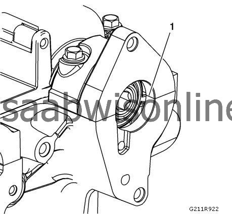
12.
|
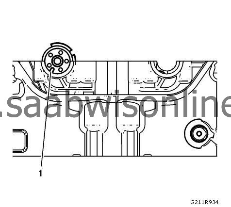
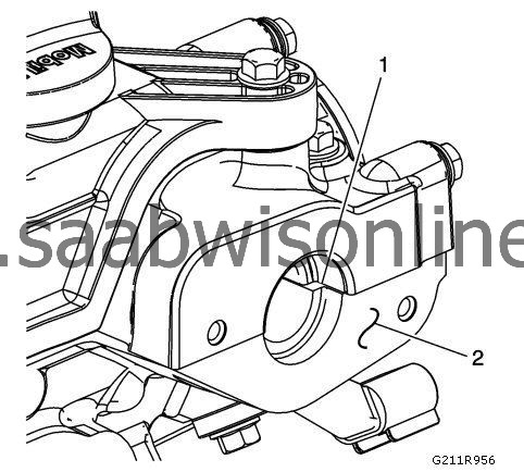
Remove all excess sealing material from the power brake booster pump bore (1), and ensure the bore and gasket sealing surface is clean and free of debris. Do not allow any excess sealing material to remain within the cylinder head or on any sealing surface.
|
|
Intake Camshaft and Components Installation
|
|
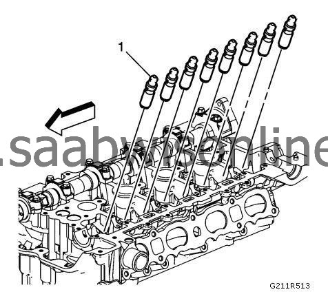
1.
|
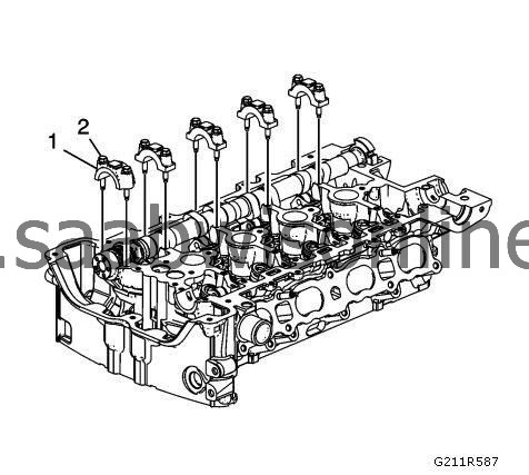
Install the hydraulic lash adjusters (1) into their bores in the cylinder head.
|
|
3.
|
Lubricate the valve tips (1).
|
|
4.
|
|
Note
|
|
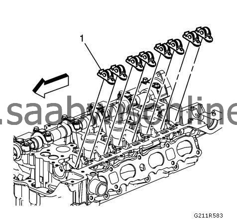
Used roller followers must be returned to the original position on the camshaft. If the camshaft is being replaced, the roller followers actuated by the camshaft must also be replaced.
|
Position the roller followers (1) on the tip of the valve stem and on the lash adjuster. Lubricate the roller followers, refer to
Adhesives, Fluids, Lubricants, and Sealers (LDK, LHU)
.
|
|
5.
|
|
Note
|
|
The engine is timed top dead center exhaust stroke.
|
When installing the camshafts, ensure the exhaust camshaft notch is in the 7 o"clock position (1). The number 1 piston should be at top dead center (TDC), crankshaft key at 12 o"clock.
|
|
7.
|
Rotate the oil seal in the groove of the number one camshaft journal so the split line (1) is at approximately the 12:00 position before installing the camshaft caps.
|
|
8.
|
|
Note
|
|
The number 1 cylinder must be at top dead center (TDC), crankshaft keyway at the 12 o'clock position.
|
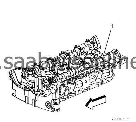
Install the intake camshaft with the notch on the front at approximately the 5 o'clock position (1).
|
|
9.
|
Install the camshaft caps (1) and hand start the camshaft cap bolts.
|
|
10.
|
Tighten the camshaft cap bolts in increments of 3 turns until they are seated. Tighten the camshaft cap to
10 Nm (89 lb in)
.
|
|
11.
|
|
Note
|
|
It is critical during installation to ensure the bearing rear cap and cylinder head alignment is correct and the mating surfaces are flush.
|
|
•
|
Ensure that all sealing material has been removed from the components, and the sealing surfaces are clean and free of contamination prior to applying the sealer.
|
|
•
|
Install and align the rear cap within 20 minutes of applying the sealer.
|
|
Note
|
|
Apply the sealer to all locations centrally locating the bead on the rail.
|
|
•
|
Run bead to 5.0 mm, dimension a, as shown.
|
|
•
|
Where the cap ends on the perimeter rail, extend bead approximately 4.0 mm beyond edge of cap.
|
|
•
|
Run bead, dimension c, 32 mm from the edge of the cylinder head as shown.
|
|
•
|
Run beads, dimension b, 20 mm from edge of cylinder head as shown.
|
Apply a 2.5 mm bead of sealer to the cylinder head at the intake camshaft bearing rear cap mating surface. Refer to
Adhesives, Fluids, Lubricants, and Sealers (LDK, LHU)
.
|
|
12.
|
Install the number 6 intake camshaft rear cap.
|
|
|
12.1.
|
Tighten the cap bolts equally to
5 Nm (44 lb in)
.
|
|
|
12.2.
|
Tighten the cap bolts equally to
10 Nm (89 lb in)
.
|
|
|
12.3.
|
Back the cap bolts out 120 degrees.
|
|
|
12.4.
|
Tighten the cap bolts evenly a final pass to
10 Nm (89 lb in)
.
|
|
13.
|
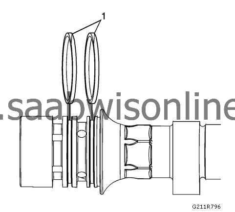
Remove all excess sealing material from the fuel pump roller lifter bore (1), and ensure the bore is free of debris. Do not allow any excess sealing material to remain within the cylinder head or on any sealing surface.
|
|
14.
|
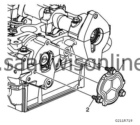
Remove all excess sealing material from the fuel pump assembly sealing surface (2).
|
|
15.
|
Ensure that the opening plate sealing surface is clean and free of excess sealing material. Install the rear cylinder head opening plate (1) and tighten the bolts to
10 Nm (89 lb in)
.
|