PRE-RELEASE
Thread Repair
| Thread Repair |
| Special Tools |
EN-43600 Thread Repair Kit
For equivalent regional tools, refer to Special Tools (LDK, LHU) .
| General Thread Repair |
| Note | ||
|
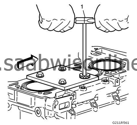
The use of a cutting fluid is recommended when performing the drilling, counterboring, and tapping procedures. |
||
|
Driver oil MUST be used on the installer driver tool. |
||
|
The tool kits are designed for use with either a suitable tap wrench or drill motor. |
Refer to Adhesives, Fluids, Lubricants, and Sealers (LDK, LHU) for recommended cutting fluid and driver oil.
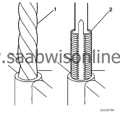
| 1. |
Drill out the threads of the damaged hole (1).
|
|
| • |
M6 inserts require a minimum drill depth of 15 mm (0.59 in).
|
| • |
M8 inserts require a minimum drill depth of 20 mm (0.79 in).
|
| • |
M10 inserts require a minimum drill depth of 23.5 mm (0.93 in).
|
| 2. |
Refer to
Safety Glasses and Compressed Air Warning
.
Using compressed air, clean out any chips. |
|
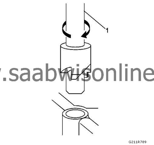
| 3. |
Counterbore the hole to the full depth permitted by the tool (1).
|
|
| 4. |
Using compressed air, clean out any chips.
|
|
| 5. |
Using a tap wrench (2), tap the threads of the drilled hole.
|
|
| • |
M6 inserts require a minimum tap depth of 15 mm (0.59 in).
|
| • |
M8 inserts require a minimum tap depth of 20 mm (0.79 in).
|
| • |
M10 inserts require a minimum tap depth of 23.5 mm (0.93 in).
|
| 6. |
Refer to
Safety Glasses and Compressed Air Warning
.
Refer to Cleaning Solvent Warning . Using compressed air, clean out any chips. |
|
| 7. |
Spray cleaner into the hole. Refer to
Adhesives, Fluids, Lubricants, and Sealers (LDK, LHU)
.
|
|
| 8. |
Using compressed air, clean any cutting oil and chips out of the hole.
|
|
| 9. |
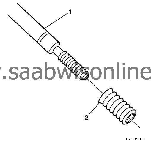
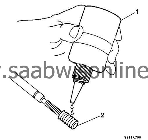
Lubricate the threads of the installer tool (2) with the driver oil (1). 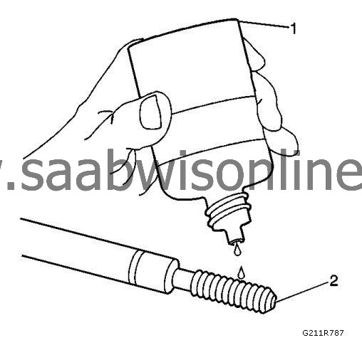
|
|||||||
| 10. |
Install the insert (2) onto the driver tool (1).
|
|
| 11. |
Apply threadlock LOCTITE™ 277,
EN-43600-109 (1)
loctite , or equivalent to the insert OD threads (2).
|
|
| 12. |
Install the insert (2) into the hole.
Install the insert until the flange of the insert contacts the counterbored surface. Continue to rotate the installer tool (1) through the insert. The installer tool will tighten up before screwing completely through the insert. This is acceptable. You are forming the bottom threads of the insert and mechanically locking the insert to the base material threads. 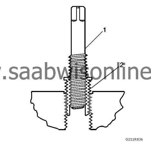
|
|
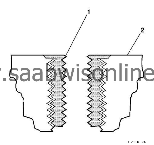
| 13. |
Inspect the insert for proper installation into the hole.
A properly installed insert (1) will be either flush or slightly below flush with the surface of the base material (2).
|
|
| Cylinder Head Bolt Hole Thread Repair |
| Note | ||
|
The use of a cutting fluid is recommended when performing the drilling, counterboring, and tapping procedures. |
||
|
Driver oil MUST be used on the installer driver tool. |
||
|
The tool kits are designed for use with either a suitable tap wrench or drill motor. |
Refer to Adhesives, Fluids, Lubricants, and Sealers (LDK, LHU) for recommended cutting fluid and driver oil.
| 1. |
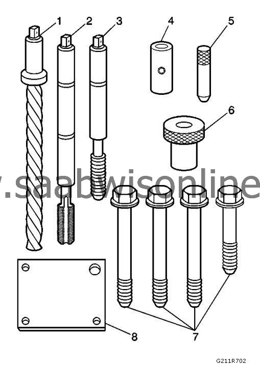
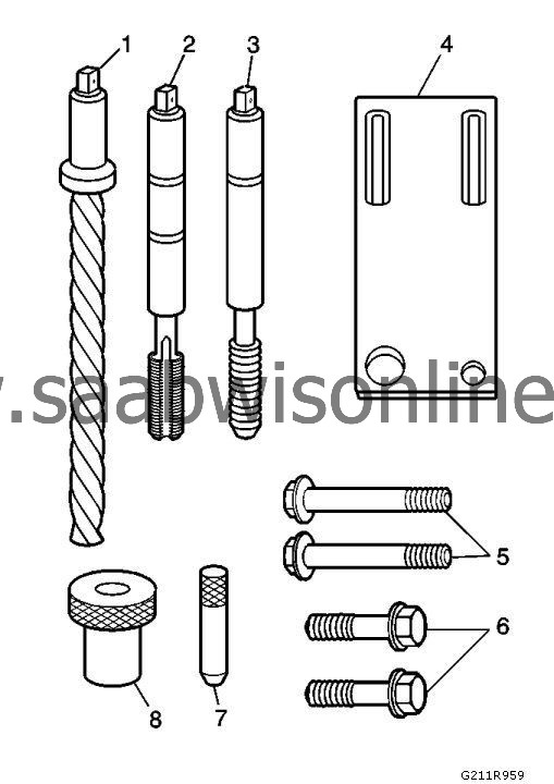
The cylinder head bolt hole thread repair kit consists of the following items:
|
|
| • |
Drill (1)
|
| • |
Tap (2)
|
| • |
Installer (3)
|
| • |
Sleeve (4)
|
| • |
Alignment Pin (5)
|
| • |
Bushing (6)
|
| • |
Bolts (7)
|
| • |
Fixture Plate (8)
|
| 2. |
Refer to
Safety Glasses and Compressed Air Warning
.
Install the fixture plate (3), bolts (1), and bushing (2) onto the engine block deck. Position the fixture plate and bushing over the hole that is to be repaired (4). 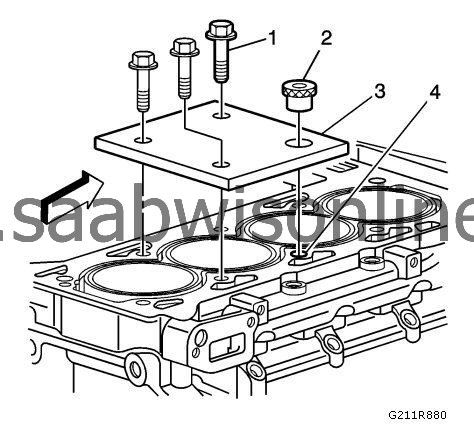
|
|
| 3. |
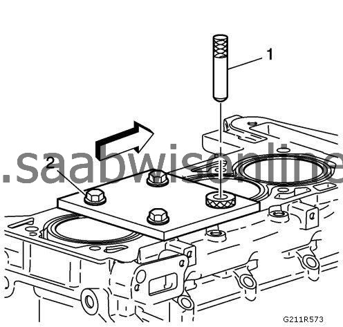
Position the alignment pin (1) through the bushing and into the hole.
|
|
| 4. |
With the alignment pin in the desired hole, tighten the fixture retaining bolts (2).
|
|
| 5. |
Remove the alignment pin from the hole.
|
|
| 6. |
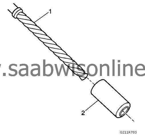
Install the sleeve (2) onto the drill (1), if required.
|
|
| 7. |
Drill out the threads of the damaged hole. Drill the hole until the stop collar (1) of the drill bit or the sleeve contacts the bushing. 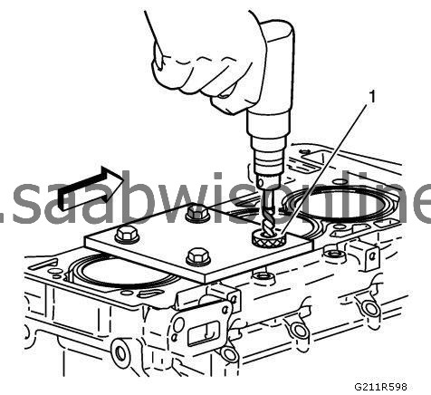
|
|||||||
| 8. |
Refer to
Safety Glasses and Compressed Air Warning
.
Using compressed air, clean out any chips. |
|
| 9. |
Using a tap wrench (1), tap the threads of the drilled hole.
|
|
| 10. |
Using a TAP wrench, tap the threads of the drilled hole.
In order to tap the new threads to the proper depth, rotate the tap into the hole until the mark (3) on the tap align with the top of the drill bushing (2). 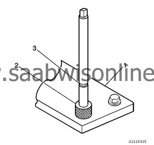
|
|
| 11. |
Remove the fixture plate (1), bushing (2), and bolts.
|
|
| 12. |
Refer to
Safety Glasses and Compressed Air Warning
.
Refer to Cleaning Solvent Warning . Using compressed air, clean out any chips. |
|
| 13. |
Spray cleaner into the hole. Refer to
Adhesives, Fluids, Lubricants, and Sealers (LDK, LHU)
.
|
|
| 14. |
Using compressed air, clean any cutting oil and chips out of the hole.
|
|
| 15. |
Lubricate the threads of the installer tool (2) with the driver oil (1).
|
|||||||
| 16. |
Install the insert (2) onto the driver tool (1).
|
|
| 17. |
Apply threadlock LOCTITE™ 277,
EN-43600-109
loctite (1) , or equivalent to the insert's OD threads (2).
|
|
| 18. |
Install the insert and driver (1) into the hole.
Rotate the driver tool until the mark on the tool aligns with the deck surface of the engine block. The installer tool will tighten up before screwing completely through the insert. This is acceptable. You are forming the bottom threads of the insert and mechanically locking the insert to the base material threads. 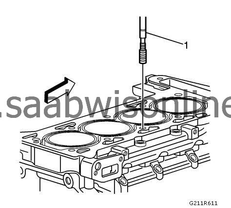
|
|
| Main Cap Bolt Hole Thread Repair |
| Note | ||
|
The use of a cutting fluid is recommended when performing the drilling, counterboring, and tapping procedures. |
||
|
Driver oil MUST be used on the installer driver tool. |
||
|
The tool kits are designed for use with either a suitable tap wrench or drill motor. |
Refer to Adhesives, Fluids, Lubricants, and Sealers (LDK, LHU) for recommended cutting fluid and driver oil.
| 1. |
The main cap bolt hole thread repair kit consists of the following items:
|
|
| • |
Drill (1)
|
| • |
Tap (2)
|
| • |
Installer (3)
|
| • |
Fixture Plate (4)
|
| • |
Long Bolts (5)
|
| • |
Short Bolts (6)
|
| • |
Alignment Pin (7)
|
| • |
Bushing (8)
|
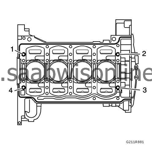
| 2. |
Remove the alignment dowel pins from the holes (1-4), if necessary.
|
|
| 3. |
Install the fixture plate (1), bolt, and bushing, onto the engine block.
Position the fixture plate and bushing over the hole that is to be repaired. 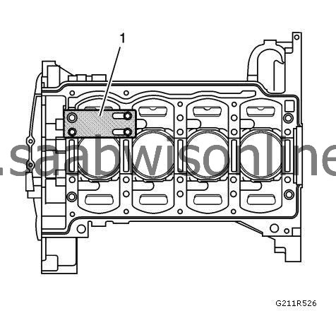
|
|
| 4. |
Position the alignment pin in the desired hole and tighten the fixture retaining bolts.
|
|
| 5. |
Drill out the damaged hole.
|
|
| 6. |
Refer to
Safety Glasses and Compressed Air Warning
.
Using compressed air, clean out any chips. |
|
| 7. |
Using a TAP wrench, tap the threads of the drilled hole.
In order to tap the new threads to the proper depth, rotate the tap into the hole until the mark (3) on the tap aligns with the top of the bushing (2).
|
|
| 8. |
Refer to
Safety Glasses and Compressed Air Warning
.
Refer to Cleaning Solvent Warning . Using compressed air, clean out any chips. |
|
| 9. |
Spray cleaner into the hole. Refer to
Adhesives, Fluids, Lubricants, and Sealers (LDK, LHU)
.
|
|
| 10. |
Using compressed air, clean any cutting oil and chips out of the hole.
|
|
| 11. |
Lubricate the threads of the installer tool (2) with the driver oil (1).
|
|||||||
| 12. |
Install the insert (2) onto the driver tool (1).
|
|
| 13. |
Apply threadlock LOCTITE™ 277, EN-43600-109 (1), or equivalent to the insert OD threads (2).
|
|
| 14. |
Install the insert and driver through the bushing (2), fixture plate (1) and into the hole. Rotate the driver tool until the mark on the tool (3) aligns with the top of the bushing (2). The installer tool will tighten up before screwing completely through the insert. This is acceptable. You are forming the bottom threads of the insert and mechanically locking the insert to the base material threads.
|
|||||||
| 15. |
Remove the driver, bushing (2), fixture plate (1), and bolts.
|
|
| 16. |
Install the alignment dowel pins in holes (1-4), if necessary.
|
|
