PRE-RELEASE
Engine Replacement
| Engine Replacement |
Special Tools
| • |
CH-49289
Centring adapter, subframe body
|
|
| • |
CH 49290
Centring Adapter Engine Subframe
|
|
| • |
DT-41623-B
Removal tool, automatic transmission
|
|
| • |
GE-8395212
Straps
|
|
| • |
MKM-558-10
Lid
|
|
For equivalent regional tools, refer to Special Tools .
| Removal Procedure |
| 1. |
Position the vehicle on a lift. and remove the key. The wheels should be in the straight-ahead position and the steering wheel should be locked in a straight ahead position.
|
|
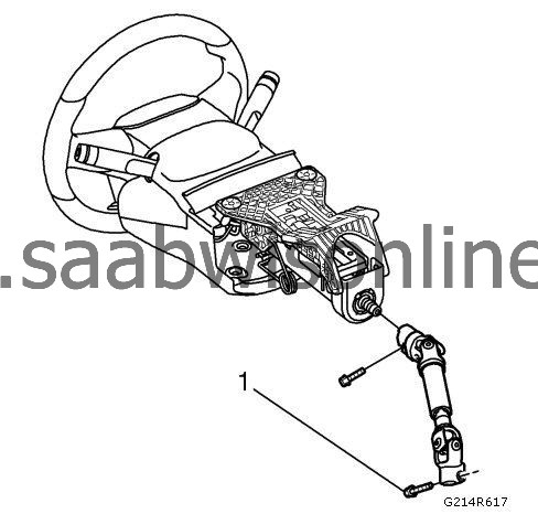
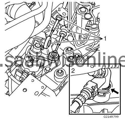
| 2. |
Loosen bolt (1) retaining steering shaft to steering gear.
|
|
| 3. |
Detach the steering shaft from the steering gear.
|
|
| 4. |
Open the coolant expansion tank cap to release pressure.
|
|||||||||
 Warning
| 5. |
Remove the upper engine cover. Refer to
Engine Cover Replacement
.
|
|
| 6. |
Remove the battery tray. Refer to
Battery Tray Replacement (Diesel)
Battery Tray Replacement (LHU/A20NFT)
.
|
|
| 7. |
Remove the front wheels. Refer to
Tire and Wheel Removal and Installation
.
|
|
| 8. |
Remove the engine cover. Refer to
Engine Shield Replacement
.
|
|
| 9. |
Remove the front bumper fascia. Refer to
Front Bumper Fascia Replacement
.
|
|
| 10. |
Drain the coolant system. Refer to
Cooling System Draining and Filling (LAU/A28NER)
Cooling System Draining and Filling (LBS/A20DTH)
Cooling System Draining and Filling (LHU/A20NFT)
.
|
|
| 11. |
Lower the vehicle.
|
|
| 12. |
Remove the air cleaner assembly. Refer to
Air Cleaner Assembly Replacement
.
|
|
| 13. |
Remove the inlet and outlet hoses to the air cooler. Refer to
Charge Air Cooler Inlet Hose Replacement (LAU/A28NER)
Charge Air Cooler Inlet Hose Replacement (LBY/A20DTR)
Charge Air Cooler Inlet Hose Replacement (LLU/A16LET)
Charge Air Cooler Inlet Hose Replacement (LBS/A20DTH)
and
Charge Air Cooler Outlet Hose Replacement (Diesel)
Charge Air Cooler Outlet Hose Replacement (LAU/A28NER)
Charge Air Cooler Outlet Hose Replacement (LLU/A16LET)
and remove the outlet pipe from the turbocharger.
|
|
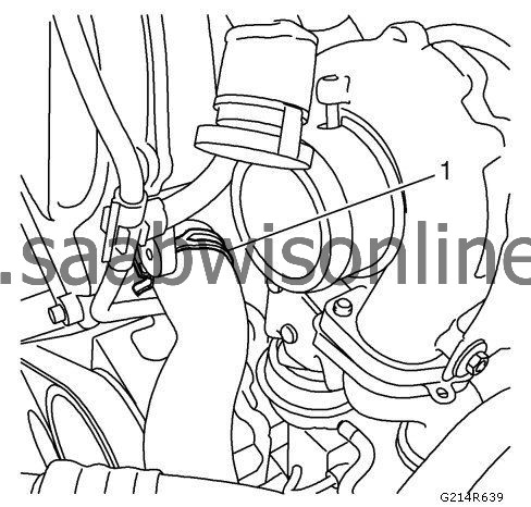
| 14. |
Detach the lower radiator hose between the radiator and cylinder head, on the cylinder head side (1).
|
|
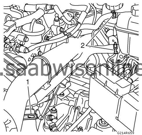
| 15. |
Remove the upper radiator hose on the thermostat side (1) and the hoses (2) on the coolant fluid expansion tank.
|
|
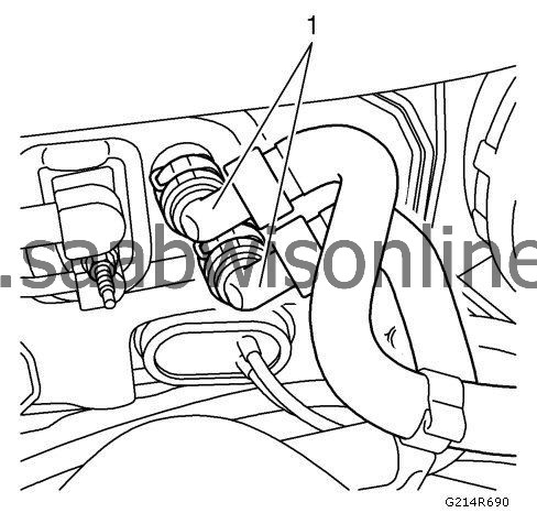
| 16. |
Remove the hoses (1) to the heat exchanger.
|
|
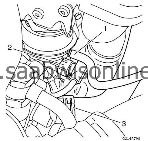
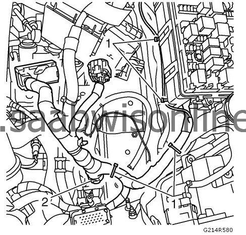
| 17. |
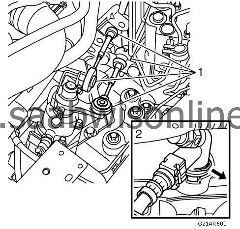
Remove the hose (1) and the electrical connector (2) from the turbo charger wastegate actuator vacuum control solenoid valve.
|
|
| 18. |
Remove the hose (3) from the inlet pipe on the steering gear pump. |
|||||||
| 19. |
Detach the return fuel hose (1) and the intake fuel hose (2). Plug both the hoses and the pipes. 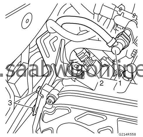
|
|||||||||||||||
| 20. |
Remove the bracket (3) of the cylinder head.
|
|
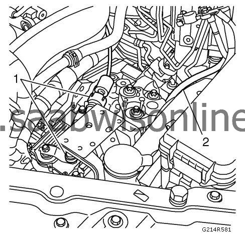
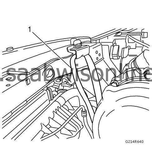
| 21. |
Remove the hose with quick coupling (1) from the vacuum pump.
|
|
| 22. |
Remove the boost pressure valves from the radiator member (2) and remove one vacuum hose (3) from the valve.
|
|
| 23. |
Remove the covers for the electrical center.
|
|
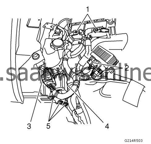
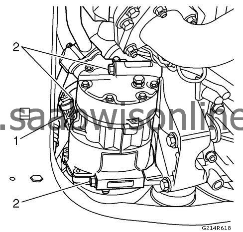
| 24. |
Remove the following components:
|
|
| • |
The engine control module (1)
|
| • |
The glow plug relay (2)
|
| • |
The connector (3) from the bracket and disconnect the connector
|
| • |
Disconnect the connector (4)
|
| • |
The ground cables (5)
|
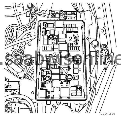
| 25. |
Remove the 4 straps (1) and 1 clip (2) that hold the wiring harness in the battery tray area.
|
|
| 26. |
Remove the following:
|
|
| 26.1. |
Disconnect the cable (1)
|
| 26.2. |
Loosen the 3 bolts (2) of the engine electrical center and remove the upper part by loosen the clips (3)
|
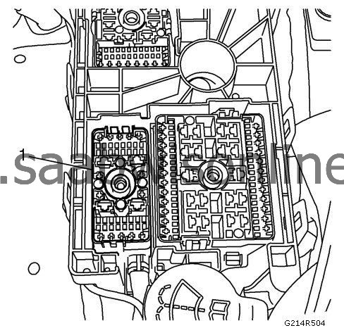
| 27. |
Remove the engine harness connector (1) from the electrical center, and fold up both engine wiring harness onto the engine.
|
|
| 28. |
For vehicles with automatic transmission, detach the radiator using coolant pipes from the
DT-41623-B
removal tool.
|
|
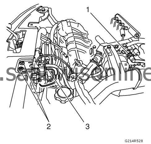
| 29. |
For vehicles with automatic transmission, remove the gear cable (1) and secure it to the expansion tank mounting using a cable tie.
|
|
| 30. |
For vehicles with automatic transmission, detach the hose (2) for automatic transmission bleeding.
|
|
| 31. |
For vehicles with manual transmission, detach the gear cables (1) from the gearbox. Carefully move them aside and secure them to the expansion tank mounting in the body using a cable tie.
|
|
| 32. |
For vehicles with manual transmission, fit the lid
MKM-558-10
lid on the brake fluid reservoir, and remove the quick coupling (2) from the clutch slave cylinder.
|
|
| 33. |
Remove the auxiliary belt. Refer to
Drive Belt Replacement
.
|
|
| 34. |
Unplug the A/C compressor connector (1) and remove the A/C compressor retaining bolts (2).
|
|
| 35. |
Secure the compressor to the bracket on the radiator member with one strap (1). Use
GE-8395212
Straps.
|
|
| 36. |
Undo the drive shaft center nuts. Knock loose the drive shafts from the hubs. Use a suitable puller or a brass drift with mallet.
|
|
| 38. |
Remove the outer steering rod. Refer to
Steering Knuckle Replacement (GNA)
Steering Knuckle Replacement (GNB)
.
|
|
| 39. |
Undo the upper anti-roll bar links. Refer to
Stabilizer Shaft Link Replacement (GNC)
Stabilizer Shaft Link Replacement (GNE)
.
|
|
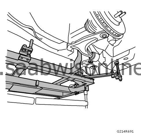
| 40. |
Separate the lower ball joint from the steering knuckle (1).
Remove the electrical harness (2) from the clips in the frame. 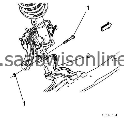
|
|
| 41. |
Fit
CH-49290
centering adapter on the subframe. Due to narrow tolerances on the drive shafts, the centring tool must be used to carefully fit the powertrain in against the subframe and body when reinstalled.
|
|
| 42. |
Lower the vehicle.
|
|
| 43. |
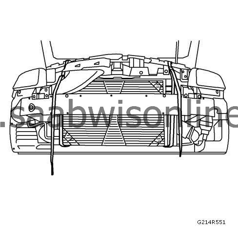
Fit two
GE-8395212
strap to the radiator member. Lower one strap down around the radiator assembly.
|
|
| 44. |
Remove the right hand engine mounting. Refer to
Engine Mount Replacement - Right Side
.
|
|
| 45. |
Remove the left engine mount. Refer to
Transmission Mount Replacement - Left Side
.
|
|
| 46. |
Raise the vehicle.
|
|
| 47. |
Position
CH-49289
centering adapter on the trolley lift.
|
|
| 48. |
Raise the trolley lift slightly so that it is firmly pressed against the subframe.
|
|
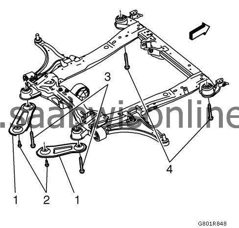
| 48.1. |
Remove the reinforcement bolts (2).
|
| 48.2. |
Remove the rear frame to body bolts (3).
|
| 48.3. |
Remove the reinforcement (1) from the vehicle.
|
| 48.4. |
Remove the front frame-to-body bolts (4).
|
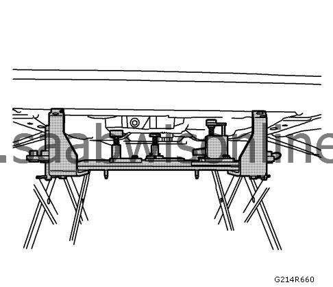
| 49. |
Carefully lower the power train on the trolley lift, making sure nothing gets caught or damaged. Pull the drive shaft universal joint out of the wheel hub.
|
|
| Installation Procedure |
| 1. |
Position the trolley lift with power train and adjust its position in relation to the body.
|
|
| 2. |
Lift up the powertrain until the drive shaft universal joint is level with the wheel hub and insert the drive shaft into the hub. Make sure nothing gets caught or damaged.
|
|
| 3. |
Position the hose for automatic transmission bleeding.
|
|
| 4. |
Make sure that the radiator core's locating pins engage in their mountings.
|
|
| 5. |
Lift a little higher and position the lower swivel joints to the steering swivel members. If necessary, adjust the trolley lift screws to provide even contact with the body. Check that the guide pins are positioned correctly relative the reference holes in the body.
|
|
| 6. |
Position the bolts and screw them through the subframe into the body.
|
|
| 7. |
Refer to
Fastener Caution
.
Raise the engine fully and tighten the subframe bolts (3), (4) and subframe stay bolts (2) to the body. Tighten, subframe160 Nm (118 lb ft)Tighten, stay42 Nm (30 lb ft)
|
|
| 8. |
Lower the trolley lift and move it out of the way.
|
|
| 9. |
Lower the vehicle.
|
|
| 10. |
Fit the right engine mount. Refer to
Engine Mount Replacement - Right Side
.
|
|
| 11. |
Fit the left engine mount. Refer to
Transmission Mount Replacement - Left Side
.
|
|
| 12. |
Raise the vehicle.
|
|
| 13. |
Remove the centring fixture.
|
|
| 14. |
Position the A/C compressor and insert the retaining bolts.
Tighten the retaining bolts (2) of the A/C compressor and plug in the A/C compressor connector (1), remove the strap.
|
|
| 15. |
Fit the auxiliary belt. Refer to
Drive Belt Replacement
.
|
|
| 17. |
Install the electrical harness (2) to the clips on the subframe. |
|||||||
| 18. |
Tighten the bolts on the lower swivel joints (1).
Tighten50 Nm (37 lb ft)
|
|
| 19. |
Position the upper anti-roll bar links. Refer to
Stabilizer Shaft Link Replacement (GNC)
Stabilizer Shaft Link Replacement (GNE)
.
|
|
| 20. |
Position the outer steering rod. Refer to
Steering Knuckle Replacement (GNA)
Steering Knuckle Replacement (GNB)
.
|
|
| 21. |
If equipped, fit the angle sensor bracket to the suspension arm. Secure the cable to the subframe and plug in the connector of the headlamp angle sensor.
|
|
| 22. |
Lower the vehicle.
|
|
| 23. |
Attach the lower radiator hoses between the radiator and cylinder head, on the cylinder head side (1).
|
|
| 24. |
Attach the upper radiator hose on the thermostat side (1).
|
|
| 25. |
Attach the hoses (2) to the coolant fluid expansion tank.
|
|
| 26. |
Attach the hoses (1) to the heat exchanger.
|
|
| 27. |
Attach inlet pipe to charge air cooler. Refer to
Charge Air Cooler Inlet Hose Replacement (LAU/A28NER)
Charge Air Cooler Inlet Hose Replacement (LBY/A20DTR)
Charge Air Cooler Inlet Hose Replacement (LLU/A16LET)
Charge Air Cooler Inlet Hose Replacement (LBS/A20DTH)
.
|
|
| 28. |
Install outlet pipe to turbocharger.
Tighten22 Nm (16 lb ft) |
|
| 29. |
Install outlet pipe to charge air cooler. Refer to
Charge Air Cooler Outlet Hose Replacement (Diesel)
Charge Air Cooler Outlet Hose Replacement (LAU/A28NER)
Charge Air Cooler Outlet Hose Replacement (LLU/A16LET)
.
|
|
| 30. |
Attach the hose (3) to the inlet pipe on the steering gear pump.
|
|
| 31. |
Attach the hose (1) and the electrical connector (2) to the turbo charger wastegate actuator vacuum control solenoid valve.
|
|
| 32. |
Remove the straps from the radiator.
|
|
| 33. |
For vehicles with manual transmission, attach the quick coupling (2) to the clutch slave cylinder and remove the lid
MKM-558-10
lid from the brake fluid reservoir.
|
|
| 34. |
For vehicles with manual transmission, attach the gear cables (1) to the gearbox.
|
|
| 35. |
For vehicles with automatic transmission, position the hose (2) for automatic transmission bleeding.
|
|
| 36. |
For vehicles with automatic transmission, attach the gear cable (1).
|
|
| 37. |
For vehicles with automatic transmission, attach the oil pipes to the radiator.
|
|
| 38. |
Attach the hose with quick coupling (1) to the vacuum pump.
|
|
| 39. |
Attach the boost pressure valves to the radiator member (2) and the vacuum hose (3) to the valve.
|
|
| 40. |
Attach the engine harness connector (1) to the electrical center.
|
|
| 41. |
Attach the upper part to the clips (3). Tighten the 3 bolts (2) of the engine electrical center and connect the cable (1).
|
|
| 42. |
Fit 4 straps (1) and 1 clip (2) that holds the wiring harness in the battery tray area.
|
|
| 43. |
Make the following attachments:
|
|
| 43.1. |
Attach the ground cables (5).
|
| 43.2. |
Connect the connector (4).
|
| 43.3. |
Attach the connector (3) to the bracket and connect the connector.
|
| 43.4. |
Attach the glowplug relay (2).
|
| 43.5. |
Connect the engine control module (1).
|
| 44. |
Attach the bracket (3) to the cylinder head.
|
|
| 45. |
Attach the return (1) fuel hose and the intake (2) fuel hose.
|
|||||||||
| 46. |
Fit the air filter assembly. Refer to
Air Cleaner Assembly Replacement
.
|
|
| 47. |
Install the upper engine cover. Refer to
Engine Cover Replacement
.
|
|
| 48. |
Install the battery tray. Refer to
Battery Tray Replacement (Diesel)
Battery Tray Replacement (LHU/A20NFT)
.
|
|
| 49. |
Install battery.
|
|
| 50. |
Fill oil into power steering system. Refer to
Power Steering System Bleeding
.
|
|
| 51. |
Fit the front bumper fascia. Refer to
Front Bumper Fascia Replacement
.
|
|
| 52. |
Install the engine cover. Refer to
Engine Shield Replacement
.
|
|
| 53. |
Lower the vehicle slightly and mount the front wheels. Refer to
Tire and Wheel Removal and Installation
.
|
|
| 54. |
Lower the vehicle and tighten the hub nuts of the drive shafts.
Tighten230 Nm (170 lb ft) |
|
| 55. |
Connect the steering shaft (1) to the steering gear. Use thread locking adhesive, Loctite 242 on the bolt.
Tighten30 Nm (19 lb ft)
|
|
| 56. |
Check engine oil level and top up as necessary.
|
|
| 57. |
Filling the cooling system. Refer to
Cooling System Draining and Filling (LAU/A28NER)
Cooling System Draining and Filling (LBS/A20DTH)
Cooling System Draining and Filling (LHU/A20NFT)
.
|
|
| 58. |
Automatic: If the gearbox was drained, check the automatic transmission fluid level as described in
Transmission Fluid Level and Condition Check
.
|
|
| 59. |
Remove the wing covers and restore the vehicle's electrical functions. Refer to
Battery Replacement
.
|
|
