Piston, Connecting Rod, and Bearing Cleaning and Inspection
|
|
Piston, Connecting Rod, and Bearing Cleaning and Inspection
|
|
1.
|
|
Note
|
|
DO NOT wire brush any part of the piston.
|
Clean the piston skirts and the pins with a cleaning solvent.
|
|
2.
|
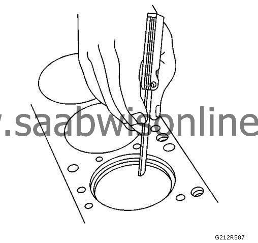
Clean the piston ring grooves with a groove cleaner. Ensure the oil ring holes and slots are clean.
|
|
Piston Inspection Procedure
|
|
1.
|
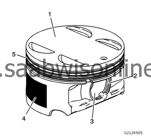
Inspect the pistons for the following conditions:
|
|
|
•
|
Cracked ring lands, skirts, or pin bosses
|
|
|
•
|
Ring grooves for nicks, burrs that may cause binding (5)
|
|
|
•
|
Warped or worn ring lands (5)
|
|
|
•
|
Piston pin retainer grooves for burrs (2)
|
|
|
•
|
Eroded areas at the top of the piston (1)
|
|
|
•
|
Scuffed or damaged skirt coating (4)
|
|
|
•
|
Worn piston pin bores or worn piston pins (3)
|
|
2.
|
Replace pistons that show any signs or damage or excessive wear.
|
|
Piston Measurement Procedure
|
|
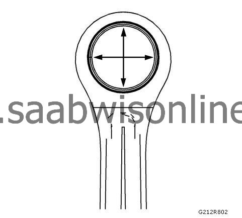
1.
|
Measure piston width using the following procedure:
|
|
|
1.1.
|
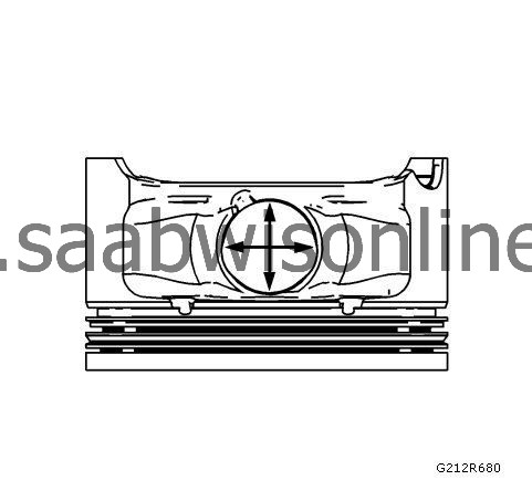
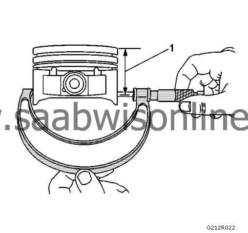
Using an outside micrometer, measure the width of the piston at 30 mm (1.181 in) below the crown, top (1), at the thrust surfaces of the piston, perpendicular to the piston pin centerline.
|
|
|
1.2.
|
Compare the measurement of the piston to its original cylinder by subtracting the piston width from the cylinder diameter.
|
|
|
1.4.
|
If the clearance obtained through measurement is greater than the provided specifications and the cylinder bores are within specification, replace the piston.
|
|
2.
|
Measure the piston pin bore to piston pin clearances using the following procedure:
|
|
|
2.1.
|
Piston pin bores and pins must be free of varnish or scuffing.
|
|
|
2.2.
|
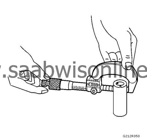
Use an outside micrometer to measure the piston pin in the piston contact areas.
|
|
4.
|
If the clearance is excessive, determine which piece is out of specification and replace as necessary.
|
|
5.
|
You must replace the piston if any of its dimensions are out of specification.
|
|
6.
|
If the new piston does not meet clearance specifications, the cylinder block may need to be oversized by 0.25 mm (0.010 in). Only one size of oversize pistons and rings is available in conjunction with service work.
|
|
Piston Ring Measurement Procedure
|
|
1.
|
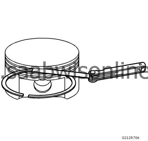
Measure the piston ring end gap using the following procedure:
|
|
|
1.1.
|
Place the piston ring in the area of the bore where the piston ring will travel approximately 25 mm (1 in) down from the deck surface. Ensure the ring is square with the cylinder bore by positioning the ring with the piston head.
|
|
|
1.3.
|
If the clearance exceeds the provided specifications, the piston rings must be replaced.
|
|
|
1.4.
|
Repeat the procedure for all the piston rings.
|
|
2.
|
Measure the piston ring side clearance using the following procedure:
|
|
|
2.1.
|
Roll the piston ring entirely around the piston ring groove. If any binding is caused by the ring groove, dress the groove with a fine file. If any binding is caused by a distorted piston ring, replace the ring.
|
|
|
2.2.
|
With the piston ring on the piston, use feeler gauges to check clearance at multiple locations.
|
|
|
2.4.
|
If the clearance is greater than specifications, replace the piston rings.
|
|
3.
|
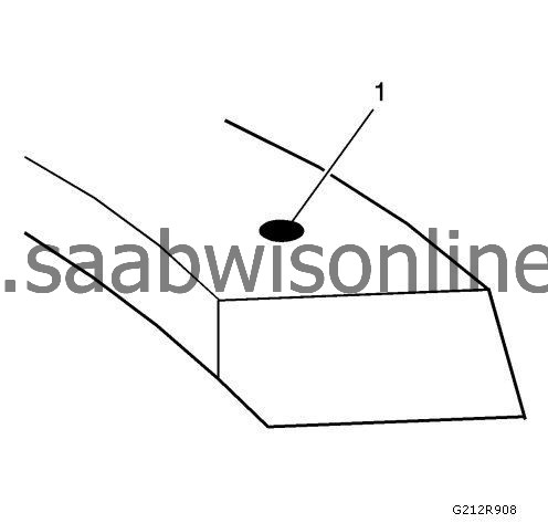
There is a locating dimple (1) on the compression rings near the end for identification. Install the compression rings with the dimple facing up.
|
|
4.
|
If the new ring does not reduce the clearance to the proper specification, install a new piston.
|
|
5.
|
If the new piston does not meet clearance specifications, the cylinder block may need to be oversized by 0.25 mm (0.010 in). Only one size of oversize pistons and rings is available in conjunction with service work.
|
|
Connecting Rod Cleaning Procedure
|
|
1.
|
Clean the connecting rods in solvent.
|
|
3.
|
Remove the connecting rod cap and clean the threads.
|
|
4.
|
Remove the connecting rod bearing and discard. Never reuse a connecting rod bearing used in a running engine.
|
|
Connecting Rod Visual Inspection Procedure
|
|
1.
|
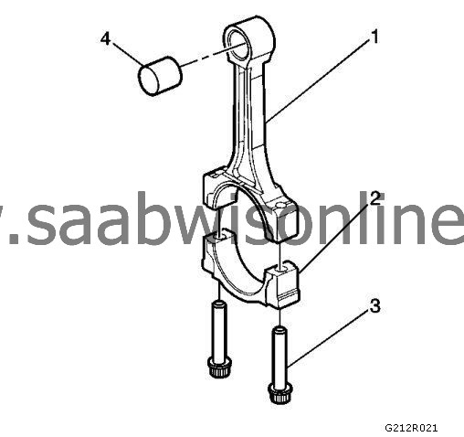
Inspect the piston pin bushing (4) for scoring or damage.
|
|
2.
|
Inspect the connecting rod beam (1) for twisting or bending.
|
|
3.
|
Inspect the rod cap (2) for any nicks or damage caused by possible interference.
|
|
4.
|
Inspect for scratches or abrasion on the rod bearing seating surface.
|
|
5.
|
|
Note
|
|
DO NOT scrape the rod or rod cap.
|
If the connecting rod bores contain minor scratches or abrasions, clean the bores in a circular direction with a light emery paper.
|
|
Connecting Rod Measurement Procedure
|
Piston Pin End
|
1.
|
|
Note
|
|
Measurements of all components should be taken with the components at normal room temperature.
|
Using an outside micrometer, take two measurements of the piston pin in the area of the connecting rod contact.
|
|
2.
|
Using an inside micrometer, measure the connecting rod piston pin bore.
|
|
3.
|
Subtract the piston pin diameter from the piston pin bore.
|
|
5.
|
If the clearance is excessive, replace the piston pin. If a new pin does not resolve the clearance problem, replace the connecting rod.
|
Connecting Rod Crankshaft Bearing End
|
1.
|
|
Note
|
|
Measurements of all components should be taken with the components at normal room temperature.
|
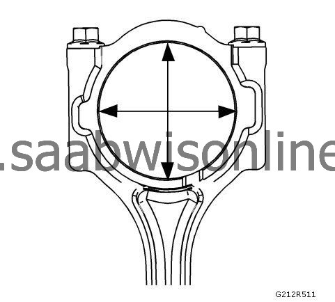
Using an inside micrometer, measure the connecting rod crankshaft bearing bore.
|
|
3.
|
Replace the connecting rod if the hole does not meet specifications. DO NOT try to repair the connecting rod.
|