PRE-RELEASE
Turbocharger System Description
| Turbocharger System Description |
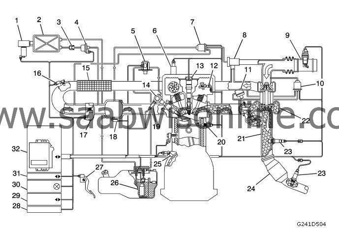
(1) Evaporative Emission (EVAP) Canister Vent Solenoid Valve
(2) EVAP Canister
(3) Non-Return Valve
(4) EVAP Canister Purge Solenoid Valve
(5) High Pressure Fuel Pump
(6) Camshaft Position Actuator Solenoid Valve
(7) Turbocharger Bypass Solenoid Valve
(8) Turbocharger Bypass Valve
(9) Mass Air Flow (MAF)/Intake Air Temperature (IAT) Sensor
(10) Turbocharger Wastegate Regulator Solenoid Valve
(11) Turbocharger Wastegate Diaphragm Valve
(12) Camshaft Position Sensor
(13) Ignition Coil/Module and Spark Plug
(14) Fuel Injector
(15) Charge Air Cooler
(16) Intake Air Pressure and Temperature Sensor
(17) Throttle Body
(18) Manifold Absolute Pressure (MAP) Sensor
(19) Fuel Rail Pressure Sensor
(20) Engine Coolant Temperature (ECT) Sensor
(21) Exhaust Manifold
(22) Turbocharger
(23) Heated Oxygen Sensor (HO2S) 1 and 2
(24) Catalytic Converter
(25) Crankshaft Position Sensor
(26) Fuel Pump Module
(27) Accelerator Pedal
(28) Theft Deterrent
(29) Data Link Connector (DLC)
(30) Malfunction Indicator Lamp (MIL)
(31) GMLAN Serial Data
(32) Engine Control Module (ECM)
| Turbocharger Description and Operation |
A turbocharger is a compressor that is used to increase the power output of an engine by increasing the mass of the oxygen and therefore the fuel entering the engine. The BorgWarner™ dual-scroll turbocharger is mounted on the exhaust manifold and the lightweight turbine is driven by the waste energy generated by the flow of the exhaust gases. The turbine is connected by a shaft to the compressor which is mounted in the induction system of the engine. The compressor vanes compress the intake air above atmospheric pressure, there by greatly increasing the density of the air entering the engine.
The turbocharger incorporates a wastegate that is controlled by the ECM, by means of a PWM solenoid, to regulate the pressure ratio of the compressor. An integral turbocharger bypass valve, controlled by the ECM through a remotely mounted solenoid, is used to prevent compressor surging and damage by opening during abrupt closed throttle conditions. The bypass valve opens during closed throttle deceleration conditions, which allows the air to recirculate in the turbocharger and maintain compressor speed. During a wide open throttle command, the bypass valve closes to optimize turbo response.
The turbocharger connects to the engine's oil system via a feed line and a return line. Mobil 1™ synthetic oil is used from the factory. Synthetic oil is required for its friction reducing capabilities and high temperature performance. There is a cooling system circuit in the turbocharger that utilizes the engine coolant to further reduce operating temperatures.
| Turbocharger Wastegate Solenoid Valve |
The wastegate valve opens and closes a bypass passage beside the turbine wheel. A spiral spring works in the closing direction while the pressure in the diaphragm works in the opening direction. The ECM supplies a PWM signal to a solenoid valve, which then allows pressure from the turbo to come through. When the pressure overcomes the spring force in the actuator, the rod begins to move, opening the wastegate valve to a corresponding degree. The ECM changes wastegate valve opening by varying the PWM signal, which controls the turbine speed.
At low loads, the wastegate valve is closed. All the exhaust gas then passes through the turbine. At high loads, the volume of exhaust gas is greater, which makes the turbine wheel rotate faster. This delivers a greater air displacement to the engine.
When the air displacement becomes so large that the current air mass per combustion cannot be controlled with the throttle alone, the turbo must be regulated. This is done by opening the wastegate valve so that some of the exhaust gas passes through the wastegate. Consequently, this gas does not contribute to driving the turbine and the turbine speed will be regulated so that the turbo air displacement will be correct.
When certain DTCs are set the ECM will limit the amount of available boost pressure. Limiting boost pressure is accomplished by the ECM controlling the wastegate actuator solenoid valve and maintaining the duty cycle at 0 %. This means that the ECM will not actively close the wastegate during greater engine loads. The system at this point is limited to mechanical boost. Mechanical boost means that the wastegate will still move, but the amount of motion is limited by the mechanical properties of the return spring within the diaphragm valve, the pneumatic properties of the actuator, and the physics of the exhaust gas flow in the exhaust system.
The turbocharger wastegate diaphragm valve assembly has a threaded rod and nut that connects the diaphragm of the valve to the wastegate. This rod is adjusted to BorgWarner™ factory specifications and is not adjustable.
The following diagrams illustrate the turbocharger wastegate closed and open conditions:
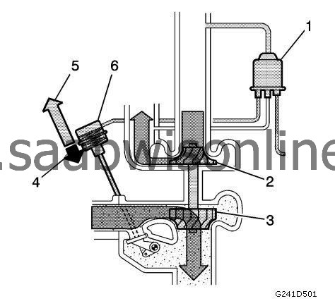
(1) Turbocharger Wastegate Actuator Solenoid Valve with Duty Cycle at 100 percent
(2) Compressor
(3) Turbine
(4) Exhaust Gas Pressure
(5) Spring Force
(6) Turbocharger Wastegate Diaphragm Valve
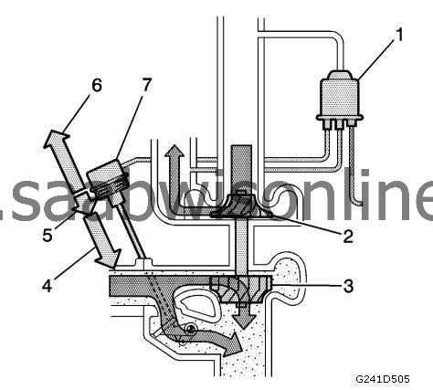
(1) Turbocharger Wastegate Actuator Solenoid Valve with Duty Cycle at 0 percent
(2) Compressor
(3) Turbine
(4) Regulating Pressure
(5) Exhaust Gas Pressure
(6) Spring Force
(7) Turbocharger Wastegate Diaphragm Valve
The wastegate is completely closed at idle. All of the exhaust energy is passing through the turbine.
During normal operation, when wide open throttle is requested at lower engine speeds, the ECM commands the wastegate solenoid with a duty cycle of 100 % to minimize any turbo lag. During engine loads in the middle and upper RPM ranges, the ECM commands the solenoid with a duty cycle of 65-80 %.
| Turbocharger Bypass Solenoid Valve |
The turbocharger bypass valve prevents the turbo from exceeding the pump limit at low flow and high pressure. This occurs when the engine is running with a load and the throttle suddenly closes. In this case, flow is almost null and pressure is very high. This not only is damaging to the turbocharger, but also generates noise and decelerates turbine speed. The ECM supplies a voltage signal to the solenoid valve output driver, which regulates the open or closed valve position.
Accelerator Pedal Depressed
The bypass valve is closed. The force in the return spring integrated in the valve presses the valve cone against its seat in the turbo housing. The valve is turned OFF.Accelerator Pedal Released
In order to avoid pressure spikes in the intake manifold and unloading or overrunning the turbo, the ECM sends a voltage signal to the bypass valve, which will then open. The compressed air on the pressure side of the turbo is led to the intake via the open valve. When the pressure drops, the turbine speed can be kept relatively high and the turbocharger is prevented from exceeding the pump limit.| Charge Air Cooler |
The turbocharger is fed via a charge air cooler This uses fresh air which is led through a heat exchanger to reduce the temperature of the warmer compressed air introduced through the induction system. Inlet air temperature can be reduced by up to 100°C (180°F), which enhances performance. This is due to the higher density of oxygen in the cooled air, which promotes optimal combustion. The charge air cooler is connected to the turbocharger and to the throttle body by flexible duct work that requires the use of special high torque fastening clamps. In order to prevent any type of air leak when servicing the ductwork, the tightening specifications and proper positioning of the clamps is critical and must be strictly adhered to.
