Fuel Injection Pump Replacement
|
|
Fuel Injection Pump Replacement
|
Special Tools
|
•
|
EN 83 95 261
Fuel Line Tool
|
For equivalent regional tools, refer to
Special Tools
.
 Warning
|
|
Always wear safety goggles when working with fuel in order to protect the eyes from fuel splash.
|
|
|
|
|
|
|
Warning
|
|
Fuel Vapors can collect while servicing fuel system parts in enclosed areas such as a trunk. To reduce the risk of fire and increased exposure to vapors:
|
|
•
|
Use forced air ventilation such as a fan set outside of the trunk.
|
|
•
|
Plug or cap any fuel system openings in order to reduce fuel vapor formation.
|
|
•
|
Clean up any spilled fuel immediately.
|
|
•
|
Avoid sparks and any source of ignition.
|
|
•
|
Use signs to alert others in the work area that fuel system work is in process.
|
|
|
|
|
|
|
Warning
|
|
Place a dry chemical (Class B) fire extinguisher nearby before performing any on-vehicle service procedures. Failure to follow these precautions may result in personal injury.
|
|
|
|
|
|
|
Warning
|
|
Do not allow smoking or the use of open flames in the area where work on the fuel or EVAP system is taking place. Anytime work is being done on the fuel system, disconnect the negative battery cable, except for those tests where battery voltage is required.
|
|
|
|
|
|
|
Note
|
|
Be very thorough in terms of cleanliness when working in the fuel system. Malfunctions can also occur due to very small dirt particles. Prevent dirt from entering the fuel system by cleaning the hoses and plugging the pipes and lines upon removal. Store the components so that contaminants cannot enter.
|
|
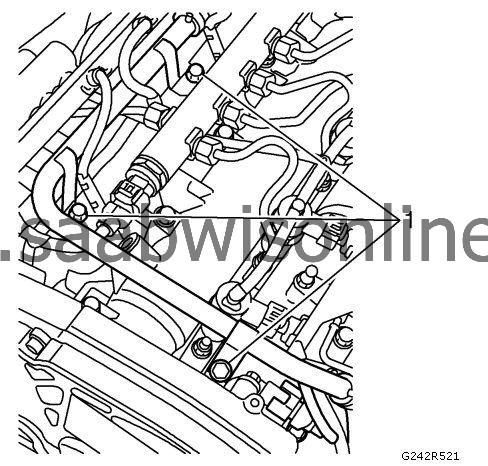
1.
|
Open the bonnet and place a wing cover over the right wing.
|
|
4.
|
Remove the bolts (1) of the crankcase ventilation pipe.
|
|
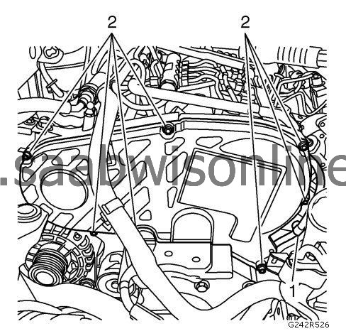
5.
|
Remove the upper timing cover bolts (2). Release clip (1) and press the turbocharger intake manifold forward.
|
|
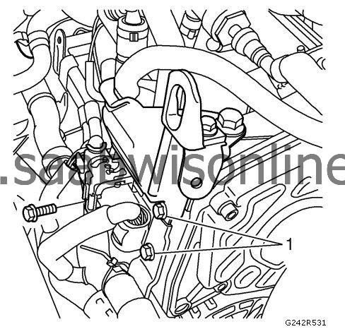
6.
|
Remove the bolts (1) and the bracket.
|
|
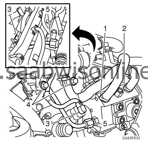
7.
|
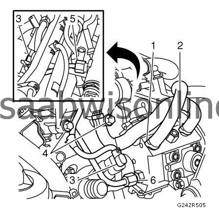
Detach the hoses on the high-pressure pump:
|
|
|
•
|
|
Note
|
|
Have a cloth on hand to catch any fuel spill.
|
Plug all connections with plugs.
|
|
|
•
|
Release the clamp and detach the fuel supply hose (1) from the high-pressure pump. Plug the hose.
|
|
|
•
|
Release the clamp and detach the return hose (2) from the high-pressure pump. Plug the hose.
|
|
|
•
|
Unplug the fuel pressure sensor connector (3) from the high-pressure pump.
|
|
|
•
|
Remove the bolts (4) of the return fuel piper.
|
|
|
•
|
Detach the high-pressure fuel line (5). Plug the nozzle pipe.
|
|
8.
|
When replacing the high-pressure pump, move aside the return fuel pipe and secure to the nozzle pipe using a cable tie.
|
|
9.
|
|
Note
|
|
Have a cloth on hand to catch any fuel spill.
|
When replacing the intake manifold/seal, detach the return fuel line from the return fuel pipe. Use
EN 83 95 261
Fuel Line Tool. Plug the connections.
|
|
10.
|
When replacing the intake manifold/seal, detach the hoses from the return fuel pipe. Remove the return fuel collector. Plug the connections.
|
|
11.
|
Place a cloth under the pump, not to lose the pulley wedge.
|
|
12.
|
|
Note
|
|
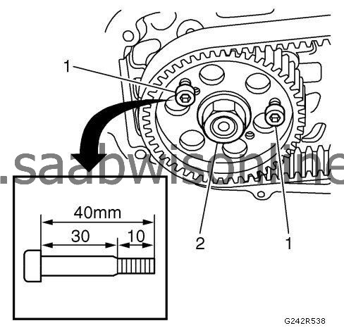
When affixing the pulley, use two hex socket head screws M6 X 40 (30 mm unthreaded and 10 mm thread). The screws must be tightened the whole length of the thread. This way the pulley is prevented from moving out of position.
|
Remove the pulley nut:
|
|
|
•
|
Turn the engine so it is possible to fit 2 Allen bolts (1) M6 x 40 (30 mm unthreaded and 10 mm threaded) through the holes in the pulley and to threads in the high-pressure pump bracket.
|
|
|
•
|
Remove the pulley nut (2).
|
|
13.
|
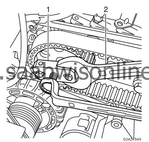
Remove the high-pressure pump from the pulley by pressing the pump out with
EN-46790
Puller (1). Counterhold with a 30 mm wrench (2). Remove the puller.
|
|
14.
|
Remove the high-pressure pump:
|
|
|
•
|
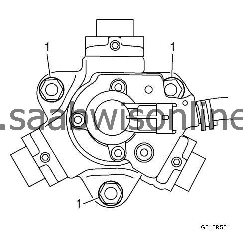
Remove the nuts and any washers (1). Use a magnet so as not to drop the washers.
|
|
|
•
|
Lift out the pump. Pay attention to the wedge.
|
|
1.
|
Refer to
Fastener Caution
.
Install the wedge to the pump and put the pump in place. Install any washers and nuts (1). It is important that the wedge fits into the groove on the pulley. Tighten fasteners to
25 Nm (18 lb ft)
.
|
|
2.
|
Install the nut (2) to the high-pressure pump pulley. Tighten to
50 Nm (37 lb ft)
.
|
|
3.
|
Remove the bolts (1) holding the pulley in place.
|
|
4.
|
Attach the hoses to the pump:
|
|
|
•
|
Remove all plugs from the pump connections.
|
|
|
•
|
Remove the plug and attach the high-pressure fuel line to rail fastener (5). Tighten to
19 Nm (14 lb ft)
. If it is difficult to get the fuel pipe in place, slacken the fuel rail retaining bolts slightly. Tighten fuel pipe fastener (6) to high pressure pump to
25 Nm (18 lb ft)
.
|
|
|
•
|
Remove the plug and attach the fuel supply hose (1) and clamp to the pump.
|
|
|
•
|
Remove the plug and attach the return hose (2) and clamp to the pump.
|
|
|
•
|
Attach the fuel pressure sensor connector (3) to the pump.
|
|
|
•
|
Install the bolts (4) of the return fuel pipe. Tighten to
9 Nm (80 lb in)
.
|
|
5.
|
|
Note
|
|
Take note of the bolt locations.
|
When replacing intake manifold/seal, attach the hoses to the return fuel collector. Attach the return fuel line.
|
|
6.
|
Install the bolts (1) and the bracket.
|
|
7.
|
Install the upper timing cover with 7 bolts (2). Press the turbocharger intake manifold forward. Attach cable clip (1).
|
|
8.
|
Install the bolts (1) of the crankcase ventilation pipe.
|
|
11.
|
To deflate the fuel system, use the diagnostic tool to activate the low pressure pump for 60 sec.
|
|
12.
|
Start the engine and turn it off.
|
