PRE-RELEASE
Fuel Tank Replacement
| Fuel Tank Replacement |
Special Tools
EN-48279 Main Fuel Pump Locking Ring Remover/InstallerFor equivalent regional tools, refer to Special Tools .
| Removal Procedure |
| 1. |
Open hood.
|
|
| 2. |
Turn the ignition OFF. |
|||||||||||||||
 Warning
| 3. |
Disconnect the negative battery cable. Refer to
Battery Negative Cable Disconnection and Connection
.
|
|
| 4. |
Relieve the fuel system pressure. Refer to
Fuel Pressure Relief
.
|
|
| 5. |
Raise and support the vehicle. Refer to
Lifting and Jacking the Vehicle
.
|
|
| 6. |
Drain the fuel tank. Refer to
Fuel Tank Draining
.
|
|
| 7. |
Remove the propeller shaft. Refer to
Propeller Shaft Replacement
.
|
|
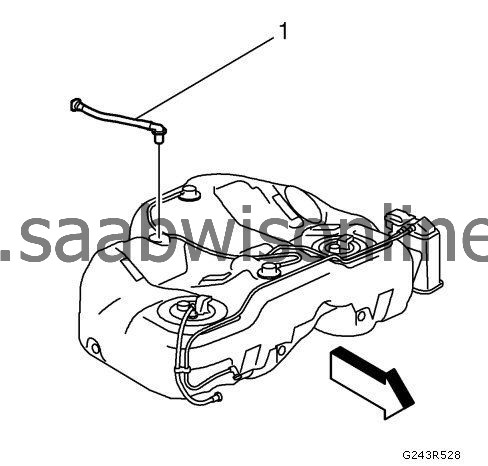
| 8. |
Disconnect the fuel tank filler vent pipe quick connector (1) from the fuel tank filler vent pipe (2). Refer to Plastic Collar Quick Connect Fitting Service . 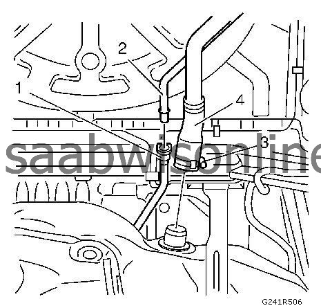
|
|||||||||
| 9. |
Remove the fuel tank filler hose fastener (3).
|
|
| 10. |
Remove the fuel tank filler hose (4).
|
|
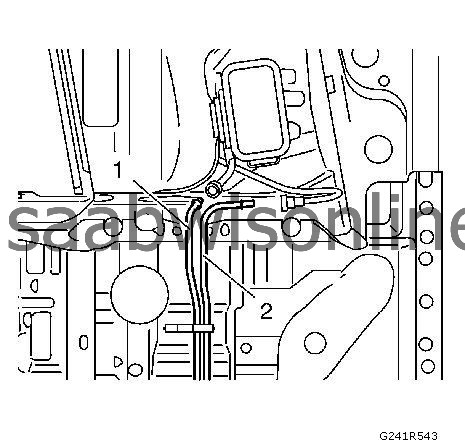
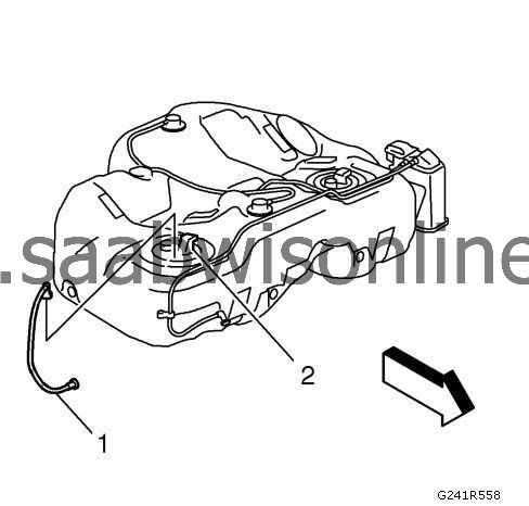
| 11. |
Disconnect the evaporative emission front pipe quick connector from the evaporative emission front pipe (1). Refer to
Plastic Collar Quick Connect Fitting Service
.
|
|
| 12. |
Disconnect the fuel feed front pipe quick connector from the fuel feed front pipe (2). Refer to
Plastic Collar Quick Connect Fitting Service
.
|
|
| 13. |
Loosen both front fasteners of the rear axle. Lower the rear axle to 20 mm (0.8 in) . Refer to Rear Axle Replacement (G96) Rear Axle Replacement (Without G96) . |
|||||||
| 14. |
Position a suitable hydraulic lift below the fuel tank.
|
|
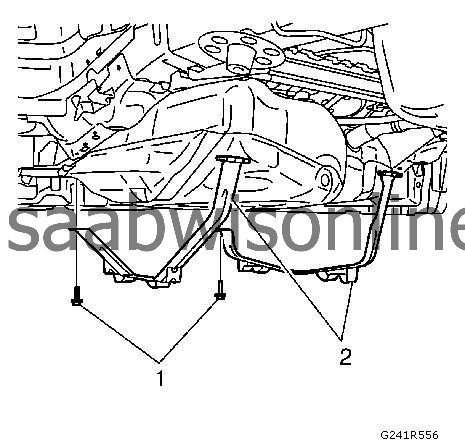
| 15. |
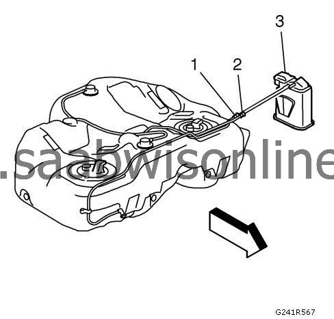
Remove both fuel tank strap fasteners (1).
|
|
| 16. |
Remove both fuel tank straps from the fuel tank (2).
|
|
| 17. |
With the aid of an assistant, lower the hydraulic lift to remove the fuel tank from the vehicle.
|
|
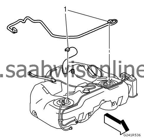
| 18. |
Disconnect both fuel tank fuel pump module wiring harness connectors (1) from the fuel tank fuel pump modules.
|
|
| 19. |
Remove the fuel tank from the hydraulic lift.
|
|
| Disassembly Procedure |
| 1. |
Remove the fuel tank filler vent pipe (1) from the fuel tank.
|
|
| 2. |
Disconnect the fuel feed pipe (1) from the fuel tank and the fuel tank fuel pump module (2). Refer to
Plastic Collar Quick Connect Fitting Service
.
|
|
| 3. |
Disconnect the evaporative emission canister purge pipe (1) and the fuel tank vent pipe (2) from the evaporative emission canister (3). Remove the evaporative emission canister (3) from the fuel tank.
|
|
| 4. |
Install the EN-48279 remover/installer (1) to the fuel pump module lock ring (2). 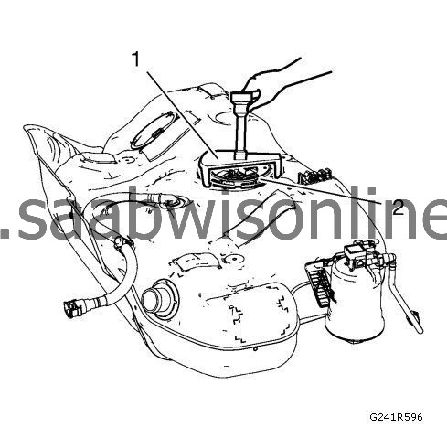
|
|||||||
| 5. |
Using the
EN-48279
remover / installer and a long breaker-bar, rotate the fuel pump module lock rings (1) in a counterclockwise direction in order to unlock the fuel pump module lock rings.
|
|
| 6. |
Remove the fuel tank fuel pump modules (2).
|
|
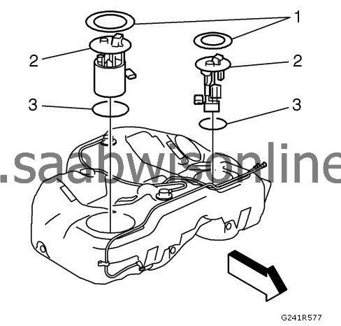
| 7. |
Remove and discard the fuel tank fuel pump module O-ring seals (3). |
|||||||
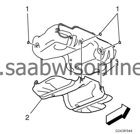
| 8. |
Remove the 4 fuel tank shield fasteners (1).
|
|
| 9. |
Remove the fuel tank shield (2).
|
|
| Assembly Procedure |
| 1. |
Install the fuel tank shield (2).
|
|
| 2. |
Install the 4 fuel tank shield fasteners (1).
|
|
| 3. |
Install NEW fuel tank fuel pump module O-ring seals (3).
|
|
| 4. |
Install the fuel tank fuel pump modules (2).
|
|
| 5. |
Install the fuel pump module lock rings (1).
|
|
| 6. |
Using the EN-48279 remover/installer and a long breaker-bar, rotate the fuel pump module lock ring (1) in a clockwise direction in order to lock the fuel pump module lock ring (2).
|
|||||||
| 7. |
Install the evaporative emission canister (3) to the fuel tank. Connect the evaporative emission canister purge pipe (1) and the fuel tank vent pipe (2) to the evaporative emission canister (3).
|
|
| 8. |
Connect the fuel feed pipe (1) to the fuel tank and the fuel tank fuel pump module (2). Refer to
Plastic Collar Quick Connect Fitting Service
.
|
|
| 9. |
Install the fuel tank filler vent pipe (1) to the fuel tank.
|
|
| Installation Procedure |
| 1. |
Refer to
Fastener Caution
.
Install the fuel tank to the hydraulic lift.
|
|
| 2. |
Connect the fuel tank fuel pump module wiring harness connectors (1) to the fuel tank fuel pump modules.
|
|
| 3. |
With the aid of an assistant, install the fuel tank to the vehicle.
|
|
| 4. |
Install both fuel tank straps to the fuel tank (2).
|
|
| 5. |
Install both fuel tank strap fasteners (1).
|
|
| 6. |
Remove the hydraulic lift from the fuel tank.
|
|
| 7. |
Install both front fasteners of the rear axle. Refer to
Rear Axle Replacement (G96)
Rear Axle Replacement (Without G96)
.
|
|
| 8. |
Connect the fuel feed front pipe quick connector to the fuel feed front pipe (2). Refer to
Plastic Collar Quick Connect Fitting Service
.
|
|
| 9. |
Connect the evaporative emission front pipe quick connector to the evaporative emission front pipe (1). Refer to
Plastic Collar Quick Connect Fitting Service
.
|
|
| 10. |
Install the fuel tank filler hose (4).
|
|
| 11. |
Install the fuel tank filler hose fastener (3) and tighten to
4 Nm (35 lb in)
.
|
|
| 12. |
Connect the fuel tank filler vent pipe quick connector (1) to the fuel tank filler vent pipe (2). Refer to
Plastic Collar Quick Connect Fitting Service
.
|
|
| 13. |
Install the propeller shaft. Refer to
Propeller Shaft Replacement
.
|
|
| 14. |
Connect the negative battery cable. Refer to
Battery Negative Cable Disconnection and Connection
.
|
|
| 15. |
Close the hood.
|
|
