PRE-RELEASE
Fuel System Description
| Fuel System Description |
| Fuel System Overview |
The fuel system is an electronic returnless on-demand design. A returnless fuel system reduces the internal temperature of the fuel tank by not returning hot fuel from the engine to the fuel tank. Reducing the internal temperature of the fuel tank results in lower evaporative emissions.
An electric turbine style fuel pump attaches to the fuel tank fuel pump module inside the fuel tank. The fuel pump supplies high pressure fuel through the fuel feed pipe to the fuel injection system. The fuel tank fuel pump module contains a reverse flow check valve. The check valve maintains fuel pressure in the fuel feed pipe and the fuel rail in order to prevent long cranking times.
| Electronic Returnless Fuel System (ERFS) |
The electronic returnless fuel system is a microprocessor controlled fuel delivery system which transports fuel from the tank to the fuel rail. It functions as an electronic replacement for a traditional, mechanical fuel pressure regulator. A pressure relief regulator valve within the fuel tank provides an added measure of over pressure protection. Desired fuel pressure is commanded by the engine control module (ECM), and transmitted to the fuel pump flow control module via a GMLAN serial data message. A liquid fuel pressure sensor provides the feedback the fuel pump flow control module requires for Closed Loop fuel pressure control.
| Fuel Pump Flow Control Module |
The fuel pump flow control module is a serviceable GMLAN module. The fuel pump flow control module receives the desired fuel pressure message from the engine control module (ECM) and controls the fuel pump located within the fuel tank to achieve the desired fuel pressure. The fuel pump flow control module sends a 25 kHz PWM signal to the fuel pump, and pump speed is changed by varying the duty cycle of this signal. Maximum current supplied to the fuel pump is 15 A. A liquid fuel pressure sensor provides fuel pressure feedback to the fuel pump flow control module.
| Fuel Pressure Sensor |
The fuel pressure sensor is a serviceable 5 V, 3-pin device. It is positioned on the fuel line in front of the fuel tank. The fuel pump flow control module provides its power and ground via the car's harness. The sensor provides a fuel pressure signal to the fuel pump flow control module, which is used to provide Closed Loop fuel pressure control.
| Fuel Tank |
The fuel tank stores the fuel supply. The fuel tank is located on the left side of the vehicle. The fuel tank is held in place by 2 metal straps that attach to the frame. The fuel tank is molded from high-density polyethylene.
The fuel tank on all wheel drive models is a saddle configuration in order to provide space for a driveshaft through the center area of the fuel tank. Because of the saddle shape of the tank, two fuel tank modules are required.
| Fuel Fill Pipe |
The fuel fill pipe has a built-in restrictor in order to prevent refueling with leaded fuel.
| Fuel Filler Cap |
|
|||||||
 Warning
The fuel fill pipe has a tethered fuel filler cap. A torque limitation counteracts the cap from being tightened to tight. To seat the cap, turn clockwise until you hear a distinctive click. This indicates that the cap is correctly torqued and fully seated. A fuel filler cap that is not fully seated may cause a malfunction in the emission system.
| Fuel Tank Fuel Pump Module |
An electric turbine style fuel pump attaches to the fuel tank fuel pump module inside the fuel tank. The fuel pump supplies fuel through the fuel feed pipe to the fuel injection system. The fuel tank fuel pump module contains a reverse flow check valve. The check valve maintains fuel pressure in the fuel feed pipe in order to prevent long cranking times.
| Primary Fuel Tank Fuel Pump Module - AWD |
The primary fuel tank fuel pump module is located inside of the right side of the fuel tank. The primary fuel tank fuel pump module consists of the following major components:
| • |
The fuel level sensor
|
|
| • |
The fuel pump and reservoir assembly
|
|
| • |
The fuel filter
|
|
| • |
The pressure relief regulator
|
|
| • |
The fuel transfer pipe
|
|
| Secondary Fuel Tank Fuel Pump Module - AWD |
The secondary fuel tank fuel pump module is located inside of the left side of the fuel tank. The secondary fuel tank fuel pump module consists of the following major components:
| • |
The fuel level sensor
|
|
| • |
The fuel pick-up
|
|
| Fuel Level Sensor |
The fuel level sensor consists of a float, a wire float arm, and a ceramic resistor card. The position of the float arm indicates the fuel level. The fuel level sensor contains a variable resistor which changes resistance in correspondence with the position of the float arm. The ECM sends the fuel level percentage via High Speed CAN-Bus to the body control module (BCM). The BCM then sends the fuel level percentage via Low Speed CAN-Bus to the instrument cluster in order to control the fuel gauge. This information is used for the instrument panel cluster fuel gauge and the low fuel warning indicator, if applicable. On all wheel drive models, the control module monitors the signal circuits of the primary fuel level sensor and the secondary fuel level sensor in order to determine the fuel level. The control module also monitors the fuel level input for various diagnostics.
| The fuel pump |
The fuel pump is mounted in the fuel tank fuel pump module reservoir. The fuel pump is an electric high-pressure pump. Fuel is pumped to the fuel injection system at a pressure that is based on feedback from the fuel pressure sensor. The fuel pump delivers a constant flow of fuel to the engine even during low fuel conditions and aggressive vehicle maneuvers. The fuel pump flex pipe acts to dampen the fuel pulses and noise generated by the fuel pump.
| Pressure Relief Regulator Valve |
The pressure relief regulator valve replaces the typical fuel pressure regulator used on a mechanical returnless fuel system. The pressure relief regulator valve is closed during normal vehicle operation. The pressure relief regulator valve is used to vent pressure during hot soaks and also functions as a fuel pressure regulator in the event of the fuel pump flow control module defaulting to 100 percent pulse width modulation (PWM) of the fuel pump. Due to variation in the fuel system pressures, the opening pressure for the pressure relief regulator valve is set higher than the pressure that is used on a mechanical returnless fuel system pressure regulator.
| Fuel Filter |
The fuel filter is contained in the fuel tank fuel pump module inside the fuel tank. The paper filter element traps particles in the fuel that may damage the fuel injection system. The filter housing is made to withstand maximum fuel system pressure, exposure to fuel additives, and changes in temperature.
| Fuel Feed Pipes |
The fuel feed pipe carries fuel from the fuel tank to the fuel injection system. The fuel feed pipe consists of 3 sections:
| • |
The rear fuel pipe is located from the top of the fuel tank to the chassis fuel pipe. The rear fuel pipe is constructed of nylon.
|
|
| • |
The chassis fuel pipe is located under the vehicle and connects the rear fuel pipe to the front fuel pipe. The chassis fuel pipe is constructed of steel.
|
|
| • |
The front fuel pipe connects the chassis fuel pipe to the fuel rail. The front fuel pipe is constructed of steel with a section of flexible hose.
|
|
| Nylon Fuel Pipes |
|
|||||||||||||||||||
Nylon pipes are constructed to withstand maximum fuel system pressure, exposure to fuel additives, and changes in temperature.
Heat resistant rubber hose or corrugated plastic conduit protect the sections of the pipes that are exposed to chafing, high temperature, or vibration.
Nylon fuel pipes are somewhat flexible and can be shaped around gradual turns under the vehicle. However, if nylon fuel pipes are forced into sharp bends, the pipes kink and restrict the fuel flow. Also, once exposed to fuel, nylon pipes may become stiffer and are more likely to kink if bent too far. Exercise special care when working on a vehicle with nylon fuel pipes.
| Quick-Connect Fittings |
Quick-connect fittings provide a simplified means of installing and connecting fuel system components. The fittings consist of a unique female connector and a compatible male pipe end. O-rings, located inside the female connector, provide the fuel seal. Integral locking tabs inside the female connector hold the fittings together.
| Fuel Rail Assembly |
The fuel rail assembly attaches to the engine intake manifold. The fuel rail assembly performs the following functions:
| • |
Positions the fuel injectors in the intake manifold
|
|
| • |
Distributes fuel evenly to the injectors
|
|
| • |
Integrates the fuel pulse dampener into the fuel metering system
|
|
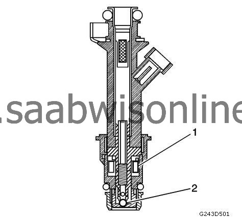
| Fuel Injectors |
| Fuel Metering Modes of Operation |
The control module monitors voltages from several sensors in order to determine how much fuel to give the engine. The control module controls the amount of fuel delivered to the engine by changing the fuel injector pulse width. The fuel is delivered under one of several modes.
| Starting Mode |
When the ignition is first turned ON, the ECM supplies ignition voltage to the fuel pump flow control module when the ECM detects that the ignition is ON. The voltage signal from the ECM to the fuel pump flow control module remains active for two seconds, unless the engine is in Crank or Run. This allows the fuel pump to build pressure in the fuel system. The control module calculates the air/fuel ratio based on inputs from the engine coolant temperature (ECT), manifold absolute pressure (MAP), mass air flow (MAF), and throttle position (TP) sensors. The system stays in starting mode until the engine speed reaches a predetermined RPM.
| Clear Flood Mode |
If the engine floods, clear the engine by pressing the accelerator pedal down to the floor and then crank the engine. When the TP sensor is at wide open throttle (WOT), the control module reduces the fuel injector pulse width in order to increase the air to fuel ratio. The control module retains this injection setting as long as the throttle is in the wide open position and the engine speed is lower than the predetermined speed. If the throttle is not held fully open, the control module returns to the start mode.
| Run Mode |
The run mode has 2 conditions called Open Loop and Closed Loop. When the engine is first started and the engine speed is above a predetermined RPM, the system begins open loop operation. The control module ignores the signal from the heated oxygen sensor (HO2S). The control module calculates the air/fuel ratio based on inputs from the ECT, MAP, MAF, and TP sensors. The system stays in Open Loop until meeting the following conditions:
| • |
The HO2S has varying voltage output, showing that the HO2S is hot enough to operate properly.
|
|
| • |
The ECT sensor is above a specified temperature.
|
|
| • |
A specific amount of time has elapsed after starting the engine.
|
|
Specific values for the above conditions exist for each different engine, and are stored in the electrically erasable programmable read-only memory (EEPROM). The system starts to work in closed loop when these values have been achieved. In closed loop the engine control module calculates the fuel mixture and the injectors' activation time based on the signals from different sensors but mainly from HO2S. This makes it possible to maintain the ratio between air/fuel very close to 14.7:1.
| Acceleration Mode |
When the driver pushes on the accelerator pedal, air flow into the cylinders increases rapidly. To prevent possible hesitation, the control module increases the pulse width to the injectors to provide extra fuel during acceleration. This is also known as power enrichment. The control module determines the amount of fuel required based upon the TP, the ECT, the MAP, the MAF, and the engine speed.
| Deceleration Mode |
When the driver releases the accelerator pedal, air flow into the engine is reduced. The control module monitors the corresponding changes in the TP, the MAF, and the MAP. The control module shuts OFF fuel completely if the deceleration is very rapid, or for long periods, such as long, closed-throttle coast-down. The fuel shuts OFF in order to prevent damage to the catalytic converters.
| Battery Voltage Correction Mode |
When the battery voltage is low, the control module compensates for the weak spark delivered by the ignition system in the following ways:
| • |
Increasing the amount of fuel delivered
|
|
| • |
Increasing the idle RPM
|
|
| • |
Increasing the ignition dwell time
|
|
| Fuel Cutoff Mode |
The control module cuts OFF fuel from the fuel injectors when the following conditions are met in order to protect the powertrain from damage and improve driveability:
| • |
The ignition is OFF. This prevents engine run-on.
|
|
| • |
The ignition is ON but there is no ignition reference signal. This prevents flooding or backfiring.
|
|
| • |
The engine speed is too high, above red line.
|
|
| • |
The vehicle speed is too high, above rated tire speed.
|
|
| • |
During an extended, high speed, closed throttle coast down-This reduces emissions and increases engine braking.
|
|
| • |
During extended deceleration, in order to prevent damage to the catalytic converters
|
|
| Fuel Trim |
The control module controls the air/fuel metering system in order to provide the best possible combination of driveability, fuel economy, and emission control. The control module monitors the HO2S signal voltage while in Closed Loop and regulates the fuel delivery by adjusting the pulse width of the injectors based on this signal. The ideal fuel trim values are around 0 percent for both short and long term fuel trim. A positive fuel trim value indicates the control module is adding fuel in order to compensate for a lean condition by increasing the pulse width. A negative fuel trim value indicates that the control module is reducing the amount of fuel in order to compensate for a rich condition by decreasing the pulse width. A change made to the fuel delivery changes the long and short term fuel trim values. The short term fuel trim values change rapidly in response to the HO2S signal voltage. These changes fine tune the engine fueling. The long term fuel trim makes coarse adjustments to fueling in order to recenter and restore control to short term fuel trim. A scan tool can be used to monitor the short and long term fuel trim values. The long term fuel trim diagnostic is based on an average of several of the long term speed load learn cells. The control module selects the cells based on the engine speed and engine load. If the control module detects an excessively lean or rich condition, the control module will set a fuel trim diagnostic trouble code (DTC).
