PRE-RELEASE
Radio interference on AM
| SERVICE INFORMATION | |
| Bulletin Nbr: | 367-2103 |
| Date: ........... | February 1999 |
| Market: | US |
| Radio interference on AM |
| Cars affected |
Saab 900 M94-. For detailed information, see the relevant type of interference under C.
| Background |
The action package in this SI has been produced for use in connection with customer complaints about interference or poor radio reception when listening to AM stations.
Always try to get the customer to describe the nature of the interference as precisely as possible, e.g. extraneous noise, tones, crackling, frying, motorboating, etc. and the circumstances in which the interference occurs.
| Parts required |
|
47 11 214
|
Processor card for main instrument unit
|
|
48 72 677
|
Interference suppression kit for ICE containing:
|
|
|
Interference suppression capacitor
|
|
|
Crimp pin
|
|
48 72 685
|
Interference suppression kit for Trionic containing:
|
|
|
Interference suppression capacitor
|
|
|
Crimp pin
|
|
51 01 985
|
Interference suppression kit for Motronic 4-cyl. containing:
|
|
|
Grounding braids (x3)
|
|
|
Ground cable (x2)
|
|
|
Interference suppression capacitor
|
|
Pressed thread screws (x3)
|
|
|
Cable tie (x3)
|
|
|
|
Lock washers (x10)
|
|
|
Hose clip
|
| Procedure |
| Note | ||
|
Only the system or systems that the following diagnostic procedures show are the cause of interference are to be rectified. |
If the car’s antenna is in poor condition, the radio will be less resistant to interference and radio reception in general will be substandard. Therefore, start fault diagnosis by inspecting the antenna.
A. Bad antenna ground connection
It is extremely important for the antenna to be properly grounded. This can be checked as described below.| 1. |
Bend aside the luggage compartment trim behind the left-hand wheel housing.
|
|
| 2. |
Disconnect the antenna cable.
|
|
| 3. |
Undo the two nuts securing the antenna.
|
|
| 4. |
Place a piece of insulating paper between the antenna bracket and the car body.
|
|
| 5. |
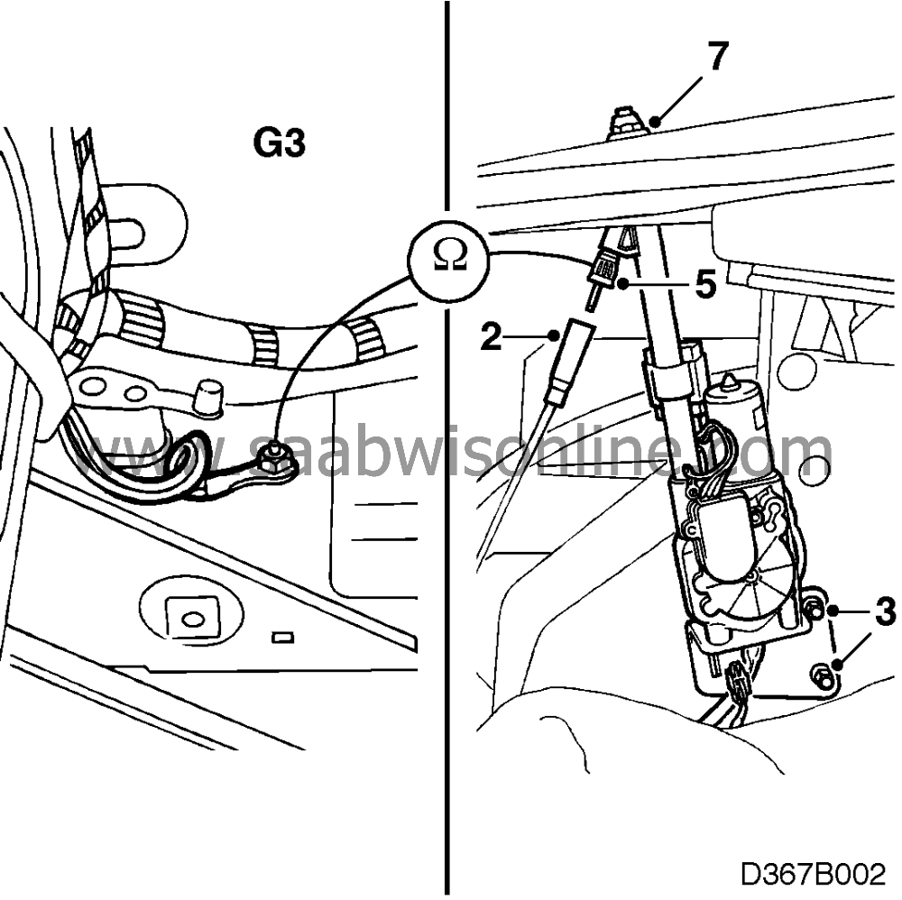
Take a resistance reading across the screen of the antenna connector and grounding point G3 under the rear left light cluster.
|
|
| 6. |
If the reading is less than 10 ohms, the ground connection is OK. Remove the paper and continue with B.
|
|
| 7. |
If the reading is above 10 ohms, adjust the star washer until it is in good contact with the body metal.
|
|
| 8. |
If the resistance reading is less than 10 ohms after adjusting the washer, remove the paper and continue with B.
|
|
| 9. |
If it is greater than 10 ohms there may be a break in the antenna. Change the antenna and continue with C.
|
|
B. Free play in the antenna rod
Free play/poor contact between the various sections of the antenna rod may occur. Check this as described below: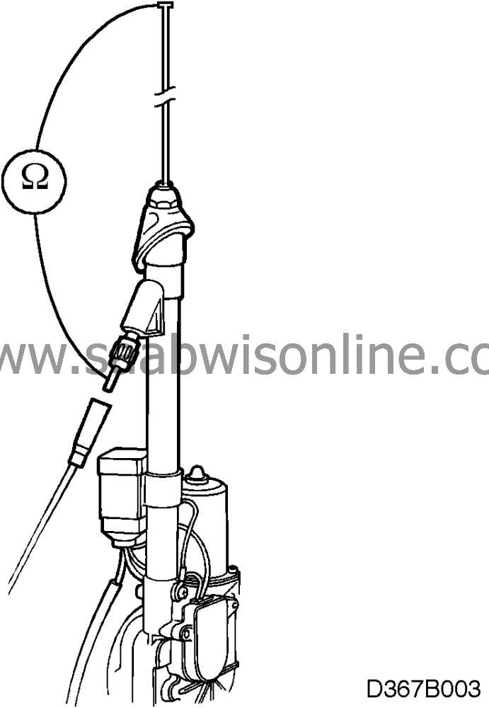
| 1. |
Switch on the radio and let the antenna extend to its fullest height.
|
|
| 2. |
Take a resistance reading across the top section of the antenna rod and the centre pin of the antenna connector.
|
|
| 3. |
If the reading is more than 30 ohms the antenna rod should be changed.
|
|
| 4. |
Connect the antenna cable.
|
|
| 5. |
Tighten the nut at the base of the antenna (unless this has already been done) and the two nuts securing the antenna.
|
|
| 6. |
Refit the luggage compartment trim.
|
|
| 7. |
If the antenna rod is dirty it must be wiped clean with a cloth (do
lubricate with wax or oil).
|
|
| 8. |
Continue as described in C.
|
|
C. Interference
Interference may be caused by different systems in different cars. To determine which system or systems are the cause of the interference, the tests must be conducted outdoors so that they will not be affected by equipment in the workshop.Interference may be of three kinds:
| • |
Background noise, see C1 on page 4.
|
|
| • |
Background tones, see C2 on page 5.
|
|
| • |
Ignition system interference, 4-cyl. Motronic system, see C3 on page 8.
|
|
C1. Background noise
On M94 cars and up to and including M96 cars, the ICE may be the cause of background noise. Starting with M97 cars, an interference suppression device has been introduced in the ICE.
To check
Turn the ignition switch to the OFF position and activate the radio. Tune in a weak station.
Remove fuse 35. This should result in a noticeable reduction in noise.
Procedure
Fit interference suppression kit 48 72 677 (CA = 30567465) as follows.
| 1. |
Remove the dashboard main fuse board.
|
|
| 2. |
Remove the lower section of the dashboard on the driver’s side.
|
|
| 3. |
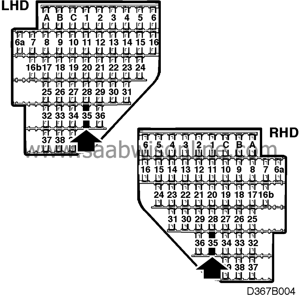
Remove fuse 35 and extract the blue/black lead from the fuse holder.
|
|
| 4. |
Cut the sleeve off the lead.
|
|
| 5. |
Cut the interference suppression capacitor lead to a length of 100 mm.
|
|
| 6. |
Twist it together with the blue/black lead in a new sleeve and reconnect the sleeve to fuse holder 35.
|
|
| 7. |
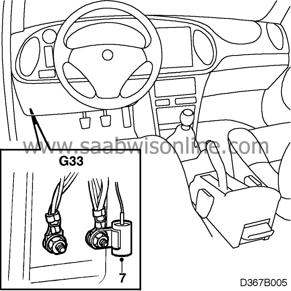
LHD: fit the interference suppression capacitor on the right-hand grounding screw at grounding point G33.
RHD: fit the interference suppression capacitor on the right-hand grounding screw at grounding point G34. 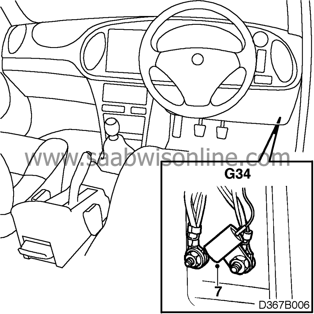
|
|
| 8. |
Refit fuse 35, switch on the radio and check the result of the above measures.
|
|
| 9. |
Refit all parts that have been removed.
|
|
C2. Background tone
A tone can be generated by three different systems. They are easy to distinguish from each other, depending on when the tone occurs.
| 1. |
The background tone varies between different stations and it comes and goes according to the light intensity sensed by the photodiode in the SID.
The fault may arise from M94 and is caused by main instrument unit 2. A suppressed processor board has been introduced in the following instrument types and VINs: |
|
| - |
miles/turbo T2034392 and T7007538 respectively
|
| - |
miles/inj T2035029 and T7008509 respectively
|
| - |
km/turbo: V2016157 and V7003308 respectively
|
| - |
km/inj: V2026515 and V7005866 respectively
See section C2.1 for checking and rectification. |
| 2. |
A steady howling tone which disappears 5 seconds after the ignition is switched off.
The fault occurs on cars equipped with Trionic M94-. See section C2.2 for checking and rectification. |
|
| 3. |
A tone occurs when the lights dim after the door has been closed.
The fault is due to the ICE and occurs on M94- cars. See section C2.3 for checking and rectification. |
|
C2.1 Main instrument unit 2
Check whether the tone comes from the main instrument unit PWM control of instrument lighting as follows:
| 1. |
Set the instrument lighting rheostat to max.
|
|
| 2. |
Shine a torch on the SID unit photodiode. The tone should increase in intensity.
|
|
| 3. |
Cover the photodiode and the tone should stop.
|
|
Rectify the fault by replacing the processor board in main instrument unit 2 with a suppressed board, part no. 47 11 214 (CA=30564136).
This board is suitable with effect from the following VIN (inclusive) :
| - |
miles/turbo R2011902
|
|
| - |
miles/inj R2015393
|
|
| - |
km/turbo R2018927
|
|
| - |
km/inj R2015980
|
|
See group 3 “Main instrument unit” for repair instructions.
C2.2 Trionic
Check whether the tone comes from the PWM control of the idle air control valve, as follows:
| 1. |
Start the engine and switch on the radio.
|
|
| 2. |
Unplug the connector from the idle air control valve in the engine bay. The tone should now disappear.
|
|
Rectify the fault by fitting interference suppression kit 48 72 685 (CA=30567466) as follows:
| 1. |
Remove the Trionic control module as described in group 2 “Trionic”.
|
|
| 2. |
Unplug the connector and extract the sleeve at position 49 (red/blue lead).
|
|
| 3. |
Cut off the sleeve.
|
|
| 4. |
Cut all but 200 mm off the interference suppression capacitor lead.
|
|
| 5. |
Twist the red/blue lead together with the interference suppression capacitor lead in a new sleeve.
|
|
| 6. |
Refit the sleeve in position 49 of the connector.
|
|
| 7. |
Plug in the connector.
|
|
| 8. |
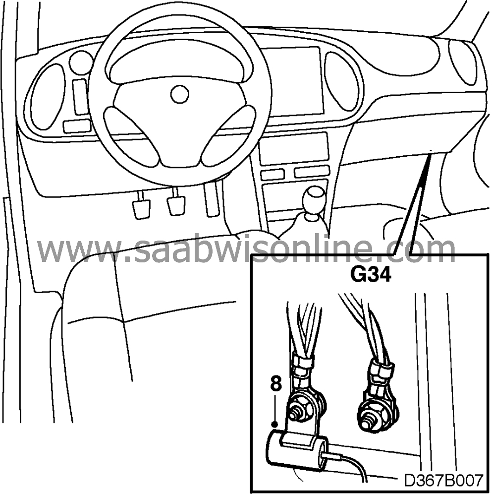
Mount the capacitor on the left-hand screw at grounding point G34.
|
|
| 9. |
Check the result of the above measures by starting the car and switching on the radio.
|
|
C2.3. ICE
Check whether the tone comes from the PWM control of interior lighting dimming when the door is closed.
| 1. |
Switch on the radio.
|
|
| 2. |
Open a door and close it again. A tone is heard while dimming of the interior lighting takes place.
|
|
Rectify the fault by fitting interference suppression kit 48 72 677 (CA=30567465) as follows:
| 1. |
Remove the ICE control module as described in group 3 “Electrical system - ICE”.
|
|
| 2. |
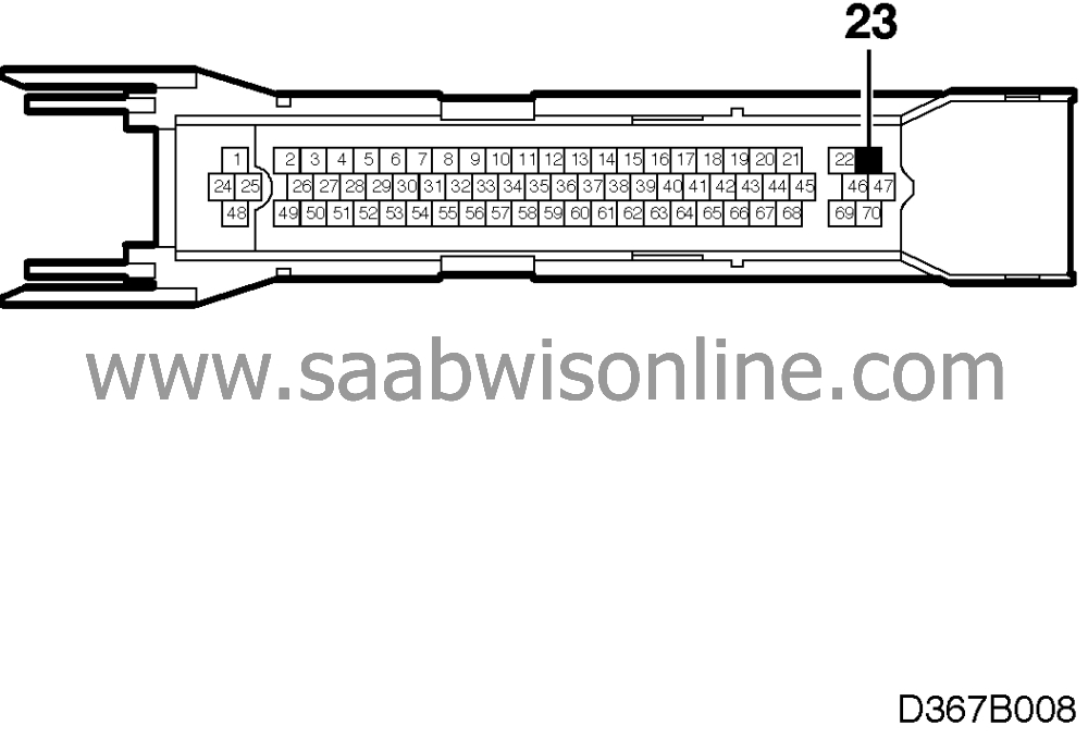
Unplug the connector and extract the sleeve at position 23 (grey/green lead).
|
|
| 3. |
Cut off the sleeve.
|
|
| 4. |
Twist the grey/green lead together with the capacitor lead in a new sleeve.
|
|
| 5. |
Refit the connector sleeve in position 23 and plug in the connector.
|
|
| 6. |
LHD: fit the interference suppression capacitor on the left-hand grounding screw at grounding point G33.
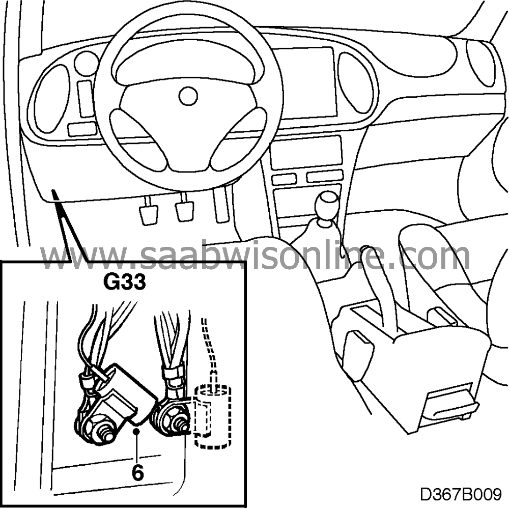
RHD: fit the interference suppression capacitor on the right-hand grounding screw at grounding point G34. 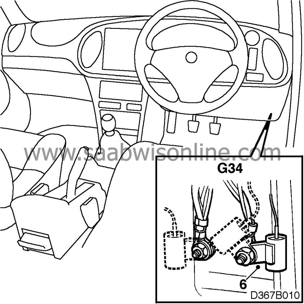
|
|
| 7. |
Check the result of the above measures by opening and closing the door when the radio is switched on.
|
|
| 8. |
Refit all parts that have been removed.
|
|
C3. Ignition system interference, 4-cyl. Motronic system
To checkIgnition system interference can arise on 4-cylinder cars fitted with the Motronic system. The “ticking” sound is most prominent at idling speed when tuned in to weak stations and will diminish as the engine speed increases.
Procedure
Rectify the fault by fitting interference suppression kit 51 01 985 (CA=30569760) as follows:
| Note | ||
|
Ensure that the customer is in possession of the radio code before commencing. |
Ground cable 1, between engine block and cross stay
| 1. |
Remove the engine resonator.
|
|
| 2. |
Place one end of the ground cable under the right-hand screw by the rear engine block lifting eye, see illustration. Fit a star washer between the screw head and the ground cable.
|
|
| 3. |
Place the other end of the ground cable in the cross stay mounting (fit a star washer between the screw head and the ground cable). Bend the cable lug 45
°
.
|
|
| 4. |
Secure the cable to the accelerator wire with a cable tie. There must be cable slack between the engine and the cable tie (to allow for engine movement).
|
|
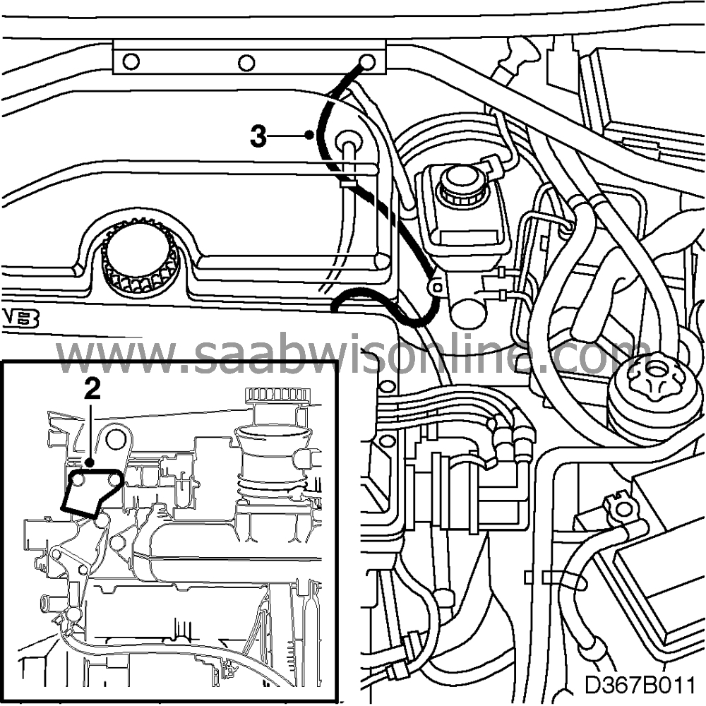
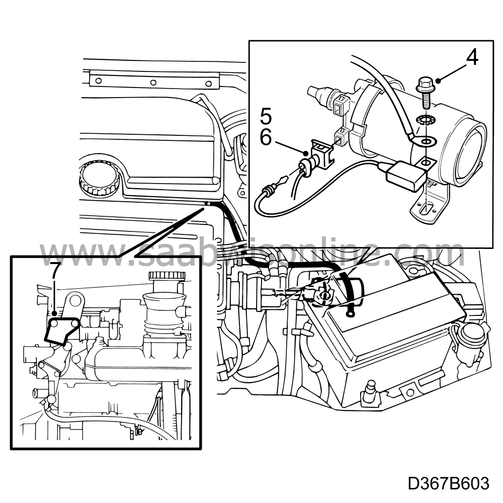
Ground cable 2, between ignition coil and engine block and on M1996-M1998 also an interference suppression capacitor on the ignition coil
| 1. |
Disconnect the battery cable (negative first) and remove the battery.
|
|
| 2. |
Undo the battery mounting and slide it forward.
|
|
| 3. |
Unscrew the front retaining screw for the ignition coil bracket.
|
|
| 4. |
Fit the interference suppression capacitor, ground cable and a star washer to the screw, see illustration, with the capacitor at the bottom. Bend up the ground cable lug approx. 45
°
.
|
|
| 5. |
Unplug the lower connector to the ignition coil.
|
|
| 6. |
Remove the blanking plug from the empty cavity and insert the capacitor connection (pos. 1).
On cars with automatic transmission and A/C, the cable must be run over the connector bracket to prevent it making contact with the A/C pipes. |
|
| 7. |
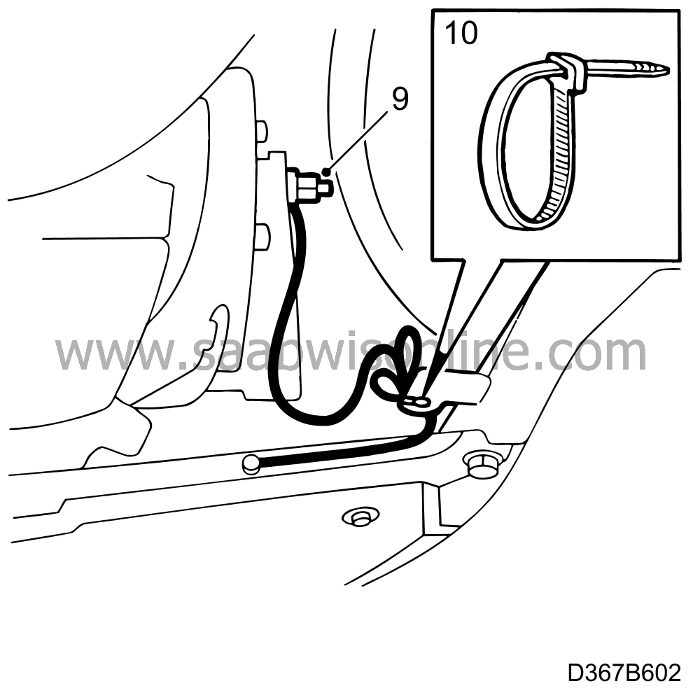
Screw the other end of the ground cable under the rear left engine block lifting eye, see illustration. Fit a star washer between the screw head and the ground cable.
|
|
| 8. |
Secure the cable to the coolant hose with a cable tie, leaving slack between the engine and the cable tie (to allow for engine movement).
|
|
| 9. |
Refit the battery mounting.
|
|
| 10. |
Refit the battery and connect the battery cables (positive first).
|
|
| 11. |
Refit the resonator. Make sure the seal is positioned correctly.
|
|
| 12. |
Set the clock and program the radio code if applicable.
|
|
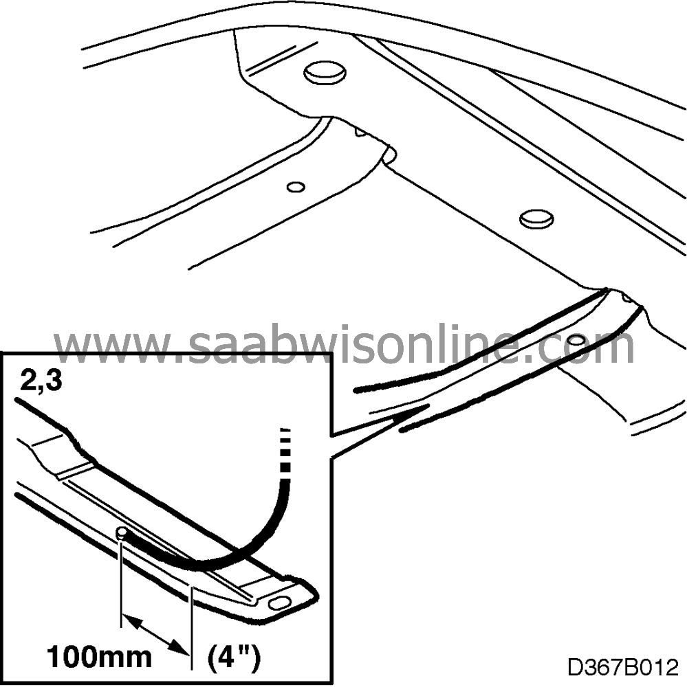
Braid 1 (approx. 650 mm = 25,5”), between gearbox and left-hand section of subframe
| 1. |
Raise the car.
|
|
| 2. |
Drill a 4 mm hole in the left-hand section of the subframe approx. 100 mm (4”) from the bend at the front, see illustration.
|
|
| 3. |
Screw on one end of the braid with a plate screw and star washer.
Seal with anti-corrosion agent. |
|
| 4. |
Cars with A/C (steps 4-8):

Run the braid along the subframe and fasten it under the plastic A/C pipe clip. |
|
| 5. |
Fit the hose clip in place at the A/C pipe joint on the compressor side.
|
|
| 6. |
Run the braid between the A/C pipes and position it round the bright-polished metal nut (compressor side).
|
|
| 7. |
Stretch the braid and tighten it round the metal nut with the hose clip.
|
|
| 8. |
Fasten the loose end of the braid to the gearbox grounding point. Fit a star washer between the screw head and the ground braid. Make sure the braid is slack enough to allow for engine movement.
|
|
| 9. |
Cars without A/C:
Fasten the other end of the braid to the gearbox grounding point. Fit a star washer between the screw head and the ground braid. |
|
| 10. |
Fasten the braid to the screw hole for the A/C pipes with a cable tie, see illustration. There must be slack between the gearbox and subframe (to allow for engine movement).
|
|

| 1. |
Drill a 4 mm hole in the right-hand section of the subframe approx. 100 mm (4”) from the bend at the front, see illustration.
|
|
| 2. |
Screw on one end of the braid with a plate screw and a star washer.
Seal with anti-corrosion agent. |
|
| 3. |
Pull up the braid and fasten the other end with the screw on the oxygen sensor cable clamp. Fit a star washer between the screw head and the ground braid.
|
|
| 4. |
Secure the braid with a cable tie round the compressor bracket mounting lug. Make sure it has sufficient slack to take up the movements of the engine.
|
|
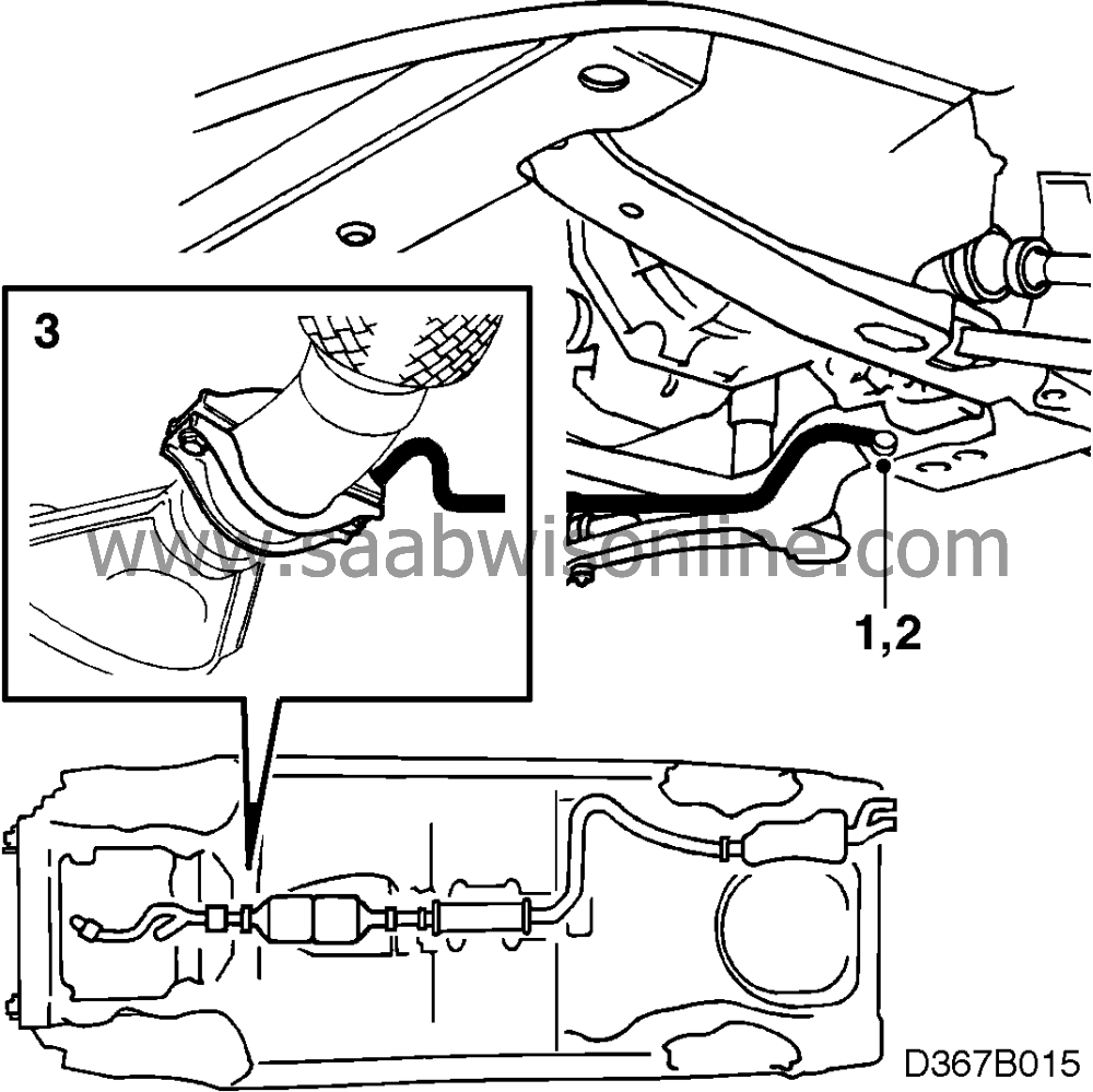
Braid 3 (approx. 210 mm = 8”), between catalytic converter and subframe
| 1. |
Drill a 4 mm hole in the rear section of the subframe, see illustration.
|
|
| 2. |
Screw on the braid with a plate screw and star washer.
Seal with anti-corrosion agent. |
|
| 3. |
Undo one of the nuts on the exhaust pipe joint clamp. Screw on the other end of the braid with a star washer under the nut.
|
|
| 4. |
Lower the car to the floor.
|
|
| Warranty information |
A Inspect/change antenna
Failed part: 36741
Fault/Reason code: 68
|
|
Check
|
Change
|
|
Location
|
0
|
0
|
|
Type of repair
|
08
|
01
|
|
Labor operation
|
straight time 0.2
|
labor op. 36741 0.2
|
B Check/change antenna
Failed part: 36743
Fault/Reason code: 68
|
|
Check
|
Change
|
|
Location
|
0
|
09
|
|
Type of repair
|
08
|
01
|
|
Labor operation
|
straight time 0.2
|
labor op. 36743 0.2
|
C1 ICE
Checking/fitting interference suppression kit
Failed part: 36568
Fault/Reason code: 68
|
|
Check
|
Fitting
|
|
Location
|
0
|
0
|
|
Type of repair
|
08
|
10
|
|
Labor operation
|
straight time 0.2
|
labor op. 36568 0.3
|
C2.1 Main instrument unit 2
Check/change processor card
Failed part:38111/38112
Fault/Reason code: 68
|
|
Check
|
Change
|
|
Location
|
0
|
09
|
|
Type of repair
|
08
|
01
|
|
Labor operation
|
straight time 0.2
|
labor op. 38129 0.8
|
C2.2 Trionic
Checking/fitting interference suppression kit
Failed part: 24810
Fault/Reason code: 68
|
|
Check
|
Fitting
|
|
Location
|
0
|
0
|
|
Type of repair
|
08
|
10
|
|
Labor operation
|
straight time 0.2
|
labor op. 24810 0.2 + straight time 0.2
|
C2.3. ICE
Checking/fitting interference suppression kit
Failed part: 36568
Fault/Reason code: 68
|
|
Check
|
Fitting
|
|
Location
|
0
|
0
|
|
Type of repair
|
08
|
10
|
|
Labor operation
|
straight time 0.2
|
labor op. 36568 0.3 + straight time 0.1
|
C3 Ignition system interference
Checking/fitting grounding braids
Failed part: 93141
Fault/Reason code: 68
|
Location
|
0
|
|
Type of repair
|
10
|
|
Labor operation
|
labor op. 93141 0.2 + straight time 0.3
|
