PRE-RELEASE
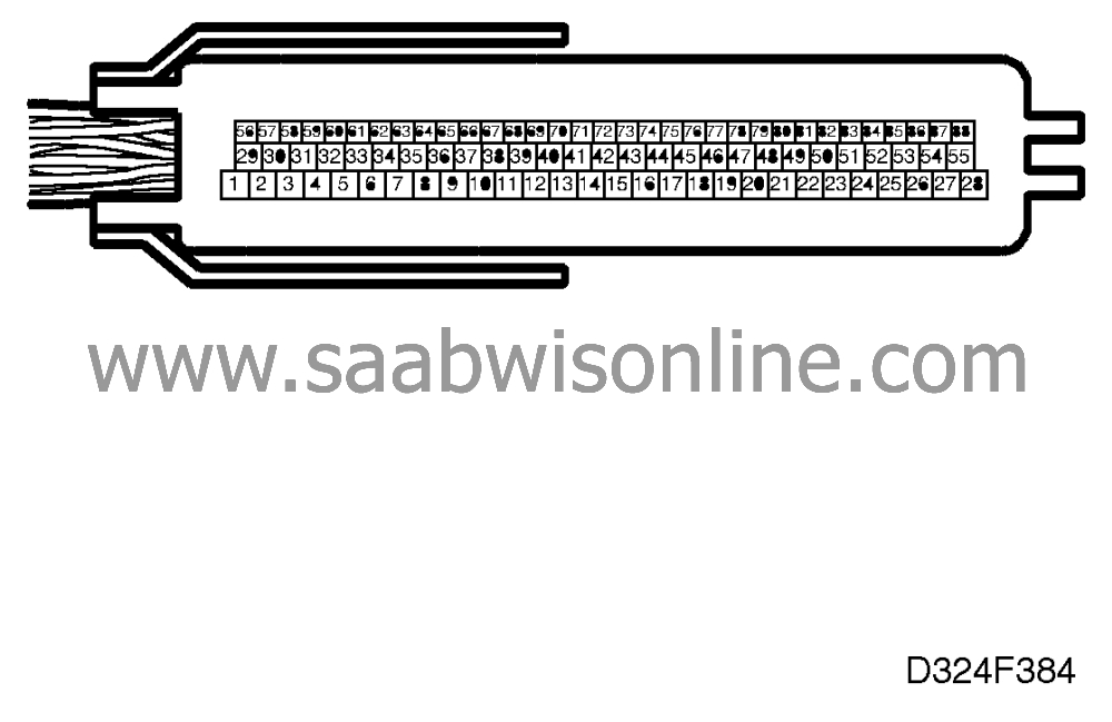
Test readings, control module connections
| Test readings, control module connections |
|
|
|
|
|
|
|
|
|
|
1
|
WH
|
Fuel pump relay
|
Out
|
T - On
|
1 - 34
|
B+
|
30 /
|
|
|
|
|
|
900 ±50
|
|
< 0.5 V
|
|
|
2
|
BN
|
IAC valve
|
Out
|
900 ±50
|
2 - 34
|
5.5 V 100 Hz 6.6 ms
|
52 /
|
|
3
|
GY
|
Injector 1
|
Out
|
900 ±50
|
3 - 55
|
B+ 4 ms
|
44 /
|
|
4
|
VT
|
Injector 4
|
Out
|
900 ±50
|
4 - 55
|
B+ 4 ms
|
44 /
|
|
5
|
|
not used
|
|
|
|
|
|
|
6
|
BK
|
Power ground
|
In
|
900 ±50
|
6 - B-
|
< 0.5 V
|
31 /
|
|
7
|
|
not used
|
|
|
|
|
|
|
8
|
YE/GN
|
CHECK ENGINE (MIL)
|
Out
|
CHECK ENGINE on
|
8 - 34
|
»
0 V
|
60 /
|
|
|
|
|
|
Check engine out
|
|
B+
|
|
|
9
|
|
not used
|
|
|
|
|
|
|
10
|
|
not used
|
|
|
|
|
|
|
11
|
YE
|
Rear heated oxygen sensor, reference
ground
|
In
|
900 ±50 Active closed
loop
|
11 - 34
|
»
0.8 V
|
32 /
|
|
12
|
BK
|
Front heated oxygen sensor,
signal
|
In
|
900 ±50 Active closed
loop
|
12 - 40
|
0.1 - 0.9 V
|
47 /
|
|
13
|
|
not used
|
|
|
|
|
|
|
14
|
|
Reference ground, mass air flow
sensor
|
|
|
|
|
32 /
|
|
15
|
|
not used
|
|
|
|
|
|
|
16
|
YE
|
Crankshaft position sensor
|
In
|
Starter motor
|
16 - 43
|
2 - 5 V ac
»
250 Hz
|
33 /
|
|
|
|
|
|
900 ±50
|
|
»
900 Hz
»
10 V
ac
|
|
|
17
|
|
not used
|
|
|
|
|
|
|
18
|
|
not used
|
|
|
|
|
|
|
19
|
OG
|
Relay, secondary air injection valve
|
Out
|
Active
|
19 - 34
|
< 0.5 V
|
54 /
|
|
|
|
|
|
Not active
|
|
B+
|
|
|
20
|
|
not used
|
|
|
|
|
|
|
21
|
|
not used
|
|
|
|
|
|
|
22
|
|
not used
|
|
|
|
|
|
|
23
|
|
not used
|
|
|
|
|
|
|
24
|
|
not used
|
|
|
|
|
|
|
25
|
GN
|
Ignition timing
|
Out
|
T - On
|
25 - 55
|
B+
|
42 /
|
|
|
|
|
|
900 ±50
|
|
150 - 200 Hz
|
|
|
26
|
PK/WH
|
+30
|
In
|
|
26 - 28
|
B+
|
29 /
|
|
27
|
BU/GY
|
Main relay
|
Out
|
T - On
|
27 - 28
|
< 0.5 V
|
30 /
|
|
|
|
|
|
T - Off
|
|
B+
|
|
|
28
|
BK
|
Ground, electronics
|
In
|
900 ±50
|
28 - B+
|
< 0.1V
|
31 /
|
|
29
|
GN
|
IAC valve
|
Out
|
900 ±50
|
29 - 34
|
»
10 V 100 Hz
»
30 %%
»
3.6
ms
|
52 /
|
|
30
|
YE/BN
|
Heating, rear heated oxygen sensor
|
In
|
900 ±50
|
30 - 34
|
»
0.5 V
|
48 /
|
|
|
|
|
|
Remove fuse 38.
|
|
»
0 V
|
|
|
31
|
GN
|
Injector 3
|
Out
|
900 ±50
|
31 - 55
|
B+ 4 ms
|
44 /
|
|
32
|
BU/PK
|
Injector 2
|
Out
|
900 ±50
|
32 - 55
|
B+ 4 ms
|
44 /
|
|
33
|
|
not used
|
|
|
|
|
|
|
34
|
BK
|
Ground, output stage
|
In
|
900 ±50
|
34 - B-
|
< 0.1V
|
31 /
|
|
35
|
BU/YE
|
SHIFT UP signal
|
In
|
900 ±50
|
35 - 34
|
< 0.1V
|
58 /
|
|
36
|
BN
|
EVAP canister purge
valve
|
Out
|
900 ±50 See page 52 for
operation.
|
36 - 34
|
15 Hz
|
53 /
|
|
37
|
BU/BN
|
Heating, front heated oxygen sensor
|
In
|
900 ±50
|
37 - 34
|
»
0.5 V
|
48 /
|
|
|
|
|
|
Remove fuse 38.
|
|
»
0 V
|
|
|
38
|
GN/OG
|
Throttle position output signal to
transmission
|
Out
|
T - On
|
38 - 34
|
»
1.2 V
|
- /
|
|
|
|
|
|
900 ±50
|
|
»
1.4 V 100 Hz
»
9 %%
»
0.9
ms
|
|
|
39
|
BK
|
Rear oxygen sensor,
signal
|
In
|
900 ±50 Active closed
loop
|
39 - 11
|
0.1 - 0.9 V
|
51 /
|
|
40
|
YE
|
Front oxygen sensor, reference
ground
|
In
|
900 ±50 Active closed
loop
|
40 - 34
|
»
0.8 V
|
32 /
|
|
41
|
GY/WH
|
Mass air flow sensor
|
In
|
900 ±50 2500 ±50
Wide open throttle(No load: A/C and all electrical equipment off.)
|
41 - 14
|
»
1.0 V
»
1.5 V
»
3.5
V
|
36 /
|
|
42
|
PK/BK
|
Vehicle speed
|
In
|
Rotate wheel slowly
|
12 - 43
|
0 and
»
12 V
|
41 /
|
|
|
|
|
|
Rotate wheel 1
turn/second
|
|
»
6 V
|
|
|
43
|
BK
|
Crankshaft position sensor
|
In
|
Starter motor cranking
|
16 - 43
|
2 - 5 V ac
»
250 Hz
|
33 /
|
|
|
|
|
|
900 ±50
|
|
»
900 Hz
»
10 V
ac
|
|
|
44
|
YE
|
Camshaft position
sensor
|
In
|
T - On, crank engine
|
44 - 28
|
0/5 V
|
35 /
|
|
45
|
|
not used
|
|
|
|
|
|
|
46
|
|
not used
|
|
|
|
|
|
|
47
|
GN/RD
|
Engine speed signal to main instrument
display panel
|
Out
|
900 ±50
|
47 - 34
|
»
5 V
»
30 Hz
|
34 /
|
|
48
|
RD/WH
|
AC RELAY
|
Out
|
900 ±50 , AC -
Off
|
48 - 34
|
B+
|
55 /
|
|
|
|
|
|
900 ±50A/C -
On
|
|
< 1V
|
|
|
49
|
|
not used
|
|
|
|
|
|
|
50
|
|
not used
|
|
|
|
|
|
|
51
|
|
not used
|
|
|
|
|
|
|
52
|
|
not used
|
|
|
|
|
|
|
53
|
|
not used
|
|
|
|
|
|
|
54
|
GN/RD
|
Voltage supply via main
relay
|
In
|
T - On
|
B+ - 54
|
< 0.5 V
|
29 /
|
|
55
|
BK
|
Ground, ignition
|
In
|
900 ±50
|
55 - B-
|
< 0.5 V
|
31 /
|
|
56
|
|
not used
|
|
|
|
|
|
|
57
|
|
not used
|
|
|
|
|
|
|
58
|
YE/GY
|
+15 circuit (via anti-theft alarm control
module)
|
In
|
T - On
|
B+ - 58
|
< 0.5 V
|
29 /
|
|
59
|
WH/BK
|
5 V power supply to
sensors
|
Out
|
T - On
|
59 - 71
|
»
5 V
|
- /
|
|
60
|
|
not used
|
|
|
|
|
|
|
61
|
|
not used
|
|
|
|
|
|
|
62
|
|
not used
|
|
|
|
|
|
|
63
|
|
not used
|
|
|
|
|
|
|
64
|
GN/GY
|
AC IN
|
In
|
T - On, (A/C On)
|
64 - 28
|
B+
|
55 /
|
|
|
|
|
|
T - On, (A/C Off)
|
|
0 V
|
|
|
65
|
BU/GN
|
Check engine request from automatic
transmission
|
In
|
On ignition switch-on
|
65 - 58
|
B+ for 1 s (LP LOp)
|
57 /
|
|
66
|
|
not used
|
|
|
|
|
|
|
67
|
BK
|
Version coding
Man/Auto
|
In
|
|
|
|
- /
|
|
68
|
|
not used
|
|
|
|
|
|
|
69
|
|
not used
|
|
|
|
|
|
|
70
|
YE
|
Knock sensor
|
In
|
»
4000 rpm
|
70 - 71
|
»
30 mV ac
|
39 /
|
|
71
|
BN/WH
|
Sensor, ground
|
In
|
900 ±50
|
71 - B-
|
< 0.5 V
|
32 /
|
|
72
|
GY/RD
|
Version coding
|
|
|
|
|
- /
|
|
73
|
BU/WH
|
Throttle potentiometer
|
In
|
T - On
|
73 - 71
|
»
0.5 V
|
37 /
|
|
|
|
|
|
T - On, wide open
throttle
|
|
»
4.5 V
|
|
|
74
|
|
not used
|
|
|
|
|
|
|
75
|
YE
|
Low fuel level
|
In
|
High fuel level T - On
|
75 - 34
|
|
59 /
|
|
|
|
|
|
Low fuel level
|
|
|
|
|
76
|
|
not used
|
|
|
|
|
|
|
77
|
GN/BK
|
Electrical load
|
In
|
900 ±50
|
77 - 71
|
B+
|
- /
|
|
|
|
|
|
900 ±50 Radiator fan
on
|
|
< 1 V
|
|
|
78
|
GN/WH
|
Engine temperature
sensor
|
In
|
Engine temperature
»
90°C
|
78 - 71
|
»
1.0 V See also technical
data
|
38 /
|
|
79
|
|
not used
|
|
|
|
|
|
|
80
|
GN/YE
|
Sensor, rough road
|
In
|
T - On
|
80 -71
|
»
2.5 V
|
61 /
|
|
81
|
|
not used
|
|
|
|
|
|
|
82
|
|
not used
|
|
|
|
|
|
|
83
|
GY/BK
|
Diagnostics communication Data link
K
|
In/Out
|
ISAT scan tool
connected
|
83 - 28
|
0 V
|
62 /
|
|
|
|
|
|
ISAT scan tool not
connected
|
|
B+
|
|
|
84
|
|
not used
|
|
|
|
|
|
|
85
|
OG/WH
|
VXL signal (torque reduction)
|
In
|
T - OFF
|
85 - 34
|
< 0.1 V
|
- /
|
|
|
|
|
|
T - On
|
|
»
9 V
|
|
|
86
|
BK/WH
|
D/R input
|
In
|
P, N, manual
|
86 - 28
|
0 V
|
- /
|
|
|
|
|
|
R, D, 3, 2, 1
|
|
B+
|
|
|
87
|
|
not used
|
|
|
|
|
|
|
88
|
|
not used
|
|
|
|
|
|
