PRE-RELEASE
Fuel injection
| Fuel injection |
Injectors
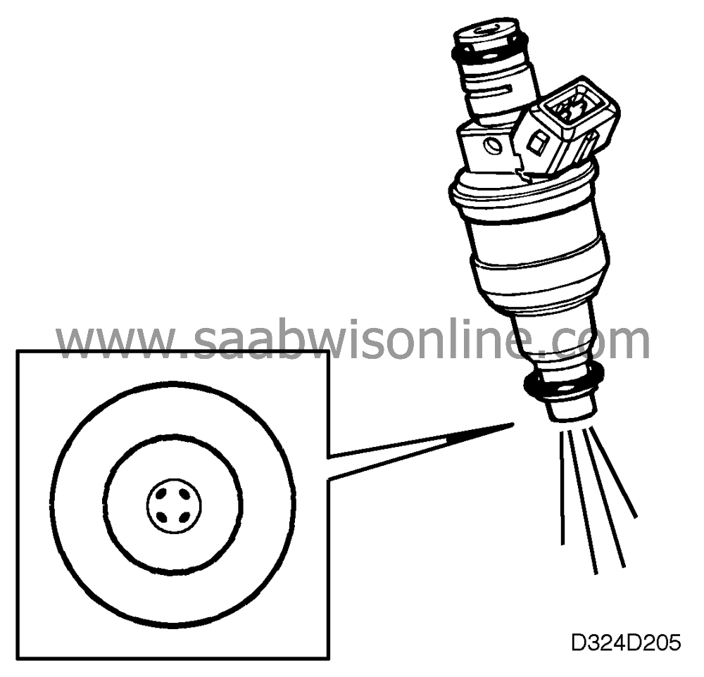
The injectors are of solenoid type with needle and seat. They open when current flows through the coil and are closed by a powerful spring when the current is cut off.For optimal combustion and consequently cleaner exhaust gases, the injectors have four holes to ensure good distribution of the fuel.
The jets of fuel are set with an extremely high degree of precision (two jets for each inlet valve). This makes big demands on the positions of the injectors. To ensure their precise location, they are fixed in position by means of the fuel rail.
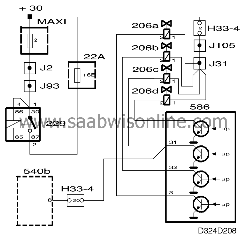
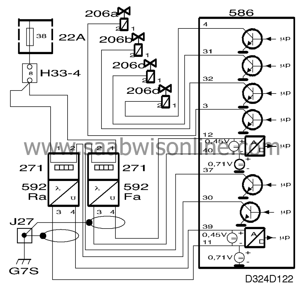
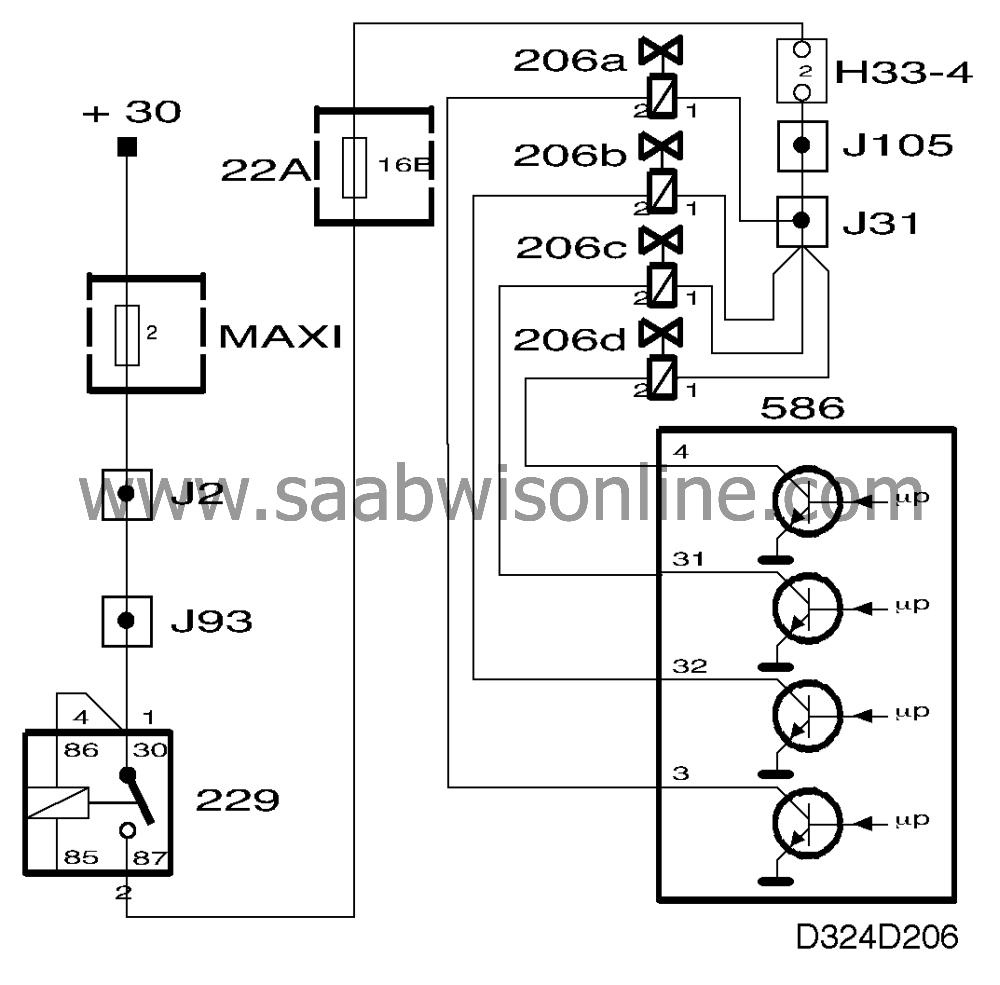
The injectors are supplied with current from the main relay. The control module grounds them as follows:
| • |
injector 1 is grounded via
pin 3
|
|
| • |
injector 2 is grounded via pin 32
|
|
| • |
injector 3 is grounded via pin 31
|
|
| • |
injector 4 is grounded via pin 4
|
|
Fuel shut-off
With the throttle completely closed and engine rpm considerably in excess of idling speed, fuel shut-off occurs. The injectors are reactivated when engine rpm approaches idling speed.Pre-injection
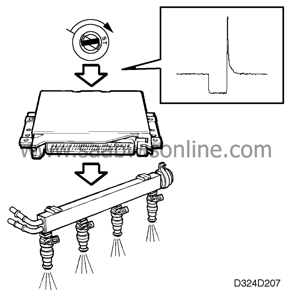
To achieve shorter starting times, pre-injection takes place if the engine coolant temperature is below 0°C (32°F).Pre-injection occurs as soon as the engine starts to turn over and the control module receives signals from the crankshaft position sensor. The control module then activates the fuel pump and all the injectors open simultaneously to squirt a small amount of fuel onto the inlet valves. The opening duration of the injectors is determined by the temperature of the coolant.
After this initial injection of fuel the system changes over to sequential fuel injection.
When the ignition switch is turned to the OFF position, the control module is still activated and so the main relay remains operated for a certain period of time.
At engine temperatures below -4 °C (25°F) this period is about 30 seconds and at engine temperatures above -4 °C (25°F) it is about 5 seconds. No pre- injection takes place if the engine is restarted during this period.
Fuel consumption
The lead from the control module to injector No. 3 is connected in parallel to the main instrument display panel which calculates fuel consumption on the basis of the duration of the injection pulses.Fuel consumption is used to obtain an accurate reading of the level of fuel in the tank and for calculating average fuel consumption in the side instrument display (SID).
Calculation of fuel injection time
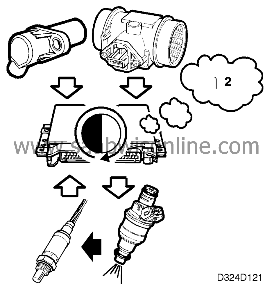
To determine how much fuel has to be injected into each intake manifold, the engine control module calculates the air mass drawn into each cylinder.The calculation is performed as follows:
Two cylinders have sucked in air during one complete engine revolution. The control module knows how much air has passed through the mass air flow sensor during this engine revolution. The air mass drawn into each cylinder is therefore one-half of the total measured.
The control module keeps the injector open exactly as long as necessary for the correct amount of fuel to be injected in relation to the air mass drawn into the cylinder.
The injection times are corrected by means of the oxygen sensors so that Lambda = 1 is obtained. The closed loop system is disengaged at wide throttle openings and full-load enrichment takes place to ensure maximum performance. A richer mixture is obtained when the accelerator is depressed and a leaner mixture when it is released. Fuel enrichment that is dependent on coolant temperature takes place when the engine is started from cold and during the warm-up period before the closed loop system is activated.
With a warmed-up engine and normal battery voltage, fuel injection times vary between about 3 ms at idling speed and about 15 ms at wide open throttle.
Closed loop
For the three way catalytic converter to function optimally, the fuel-air mixture must be stoichiometric.This means that the mixture must be neither too rich nor too lean but consist precisely of 14.7 kg of air to 1 kg of fuel (Lambda = 1).
Regardless of how precisely the air mass flowing into the engine is measured and regardless of how accurately the injection time is calculated, the fuel-air mixture will inevitably deviate from Lambda = 1.
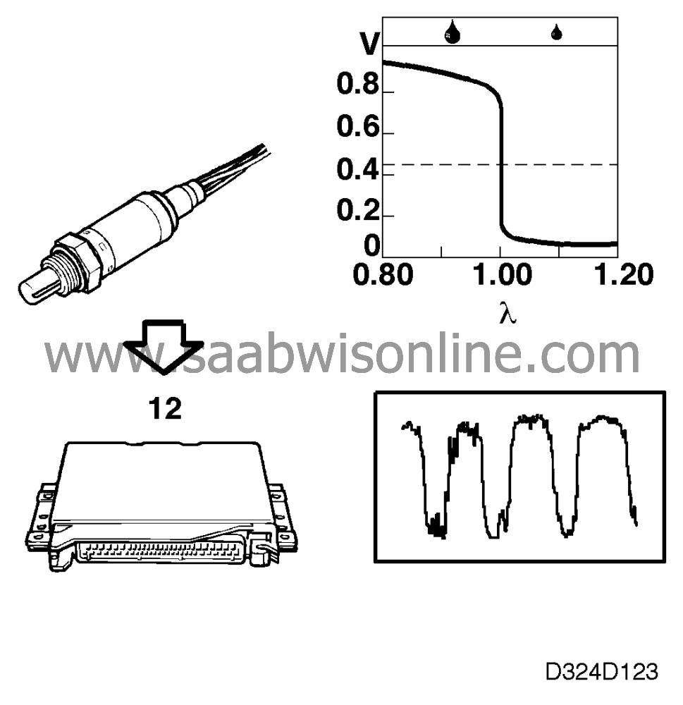
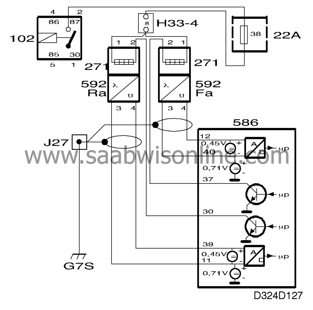
For this reason the fuel system is equipped with an oxygen sensor mounted just after the exhaust manifold.
This sensor is connected to control module pin 12 and grounded via pin 40.
The engine exhaust gases pass the oxygen sensor. A chemical reaction enables the oxygen content of the exhaust gases to be measured. The output voltage of the oxygen sensors is proportional to the current oxygen content.

| Important | ||
|
The oxygen sensor receives reference oxygen from the ambient air via the connecting cables. For this reason, contact cleaning sprays and grease must not be used on the sensor connectors. |
||
If the engine runs rich (Lambda < 1), the output voltage of the sensor will be about 0.9 V. If the engine runs lean (Lambda > 1), the output voltage of the sensor will be about 0.1 V. Sensor voltage changes very rapidly when Lambda passes 1.
When sensor voltage is low the control module adjusts the injection time slightly so that a richer mixture is obtained. The oxygen content of the exhaust gases drops and sensor voltage rises rapidly to about 0.9 V as Lambda descends below 1. The control module then reduces the injection time slightly. This process is repeated continuously, i.e. sensor voltage oscillates between about 0.1 and 0.9 V.
To measure the oxygen content of the exhaust gases the oxygen sensor has to be at a certain temperature. A pre-heating element is built into the sensor so that the closed loop system can be engaged as soon as possible after starting and to ensure that the temperature of the sensor at idling speed is sufficiently high.
The power applied through the pre-heating element's PTC resistor diminishes with rising temperature. The pre-heating element is supplied with current via the fuel pump relay and is accordingly activated as soon as the engine is started.
Lambda control is engaged as soon as engine temperature rises above 32°C (90°F) under partial load or 38°C (100°F) at idling speed.
The closed loop system is disengaged under high engine load conditions since a rich fuel-air mixture is required for optimum performance.
Adaptation
The control module first calculates the injection time using information from the mass air flow sensor and engine rpm. On the basis of information from the oxygen sensors, the injection time is then corrected so that Lambda = 1 is obtained.The closed loop system can adjust the calculated injection time by ±25 %%.
If the control module has calculated that the injection time ought to be 8 ms, the closed loop system can adjust the times down to 6 ms or up to 10 ms if necessary in order to obtain Lambda = 1.
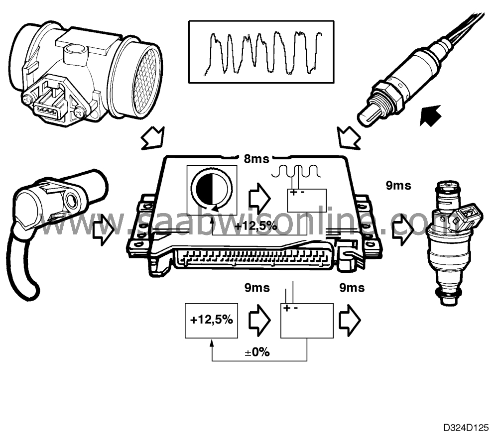
Multiplicative adaptation
For instance, if the control module calculates that the injection time should be 8 ms but the closed loop system adjusts it to 9 ms because the car's fuel pressure is somewhat low, the control module will "learn" the new injection time.This is done by correcting the basic calculation on the basis of engine rpm and information from the mass air flow sensor so that the result is an injection time of 9 ms.
The correction factor in this example is:
9/8=1.125=+12.5 %%.
The correction factor, +12.5%%, is stored in the control module's memory so that it can be used for calculating the injection time regardless of engine load and rpm. The correction factor may be ±25 %%. That is called adaptation.
Conditional for the implementation of adaptation is an activated closed loop system, a coolant temperature above 70°C (158°F) and non-operation of the EVAP canister purge valve.
The adaptation process described here takes a fairly long time because of slow age-related changes in fuel pressure, the flow of fuel through the injectors, etc.
Using an ISAT scan tool, a multiplicative adaptation readout can be obtained. Positive or negative values are perfectly normal as long as they do not exceed +25%% or fall below - 25%%.
Additive adaptation
Further adaptation takes place at idling speed. This differs from multiplicative adaptation in that it takes place very rapidly (although the same conditions as for multiplicative adaptation must be fulfilled). Another difference is that the control module does not store the result as a percentage but as injection time in ms.For instance, if the calculated injection time is 3.05 ms and the closed loop system corrects it to 3.10 ms, the control module will adapt the time to +0.05 ms. This time is then added on top of the injection time, irrespective of engine speed and load conditions.
The adapted value may be ±0.51 ms.
The purpose of additive adaptation is to compensate for air leakage, the effect of which is most noticeable at idling speed.
Using an ISAT scan tool, an additive adaptation readout can be obtained.
Positive or negative values are perfectly normal as long as they do not exceed +0.51 ms or fall below -0.51 ms.
Oxygen sensor after three-way catalytic converters
An oxygen sensor is mounted after the three way catalytic converter for diagnostic purposes.The oxygen sensor after the three way catalytic converter is connected to control module pin 11 and grounded via pin 39.
The oxygen sensor's preheating element is supplied with battery positive voltage (B+) from the fuel pump relay via fuse 38 and grounded via pin 30 of the control module. The control module disconnects the preheating circuit when the estimated exhaust temperature is so high that the sensor would be damaged if preheating continued.
To improve exhaust emission control efficiency still further, the value from the sensor after the three way catalytic converter is used to correct the closed loop system. The best emission values are obtained when the rear heated oxygen sensor's voltage is 0.6 V.
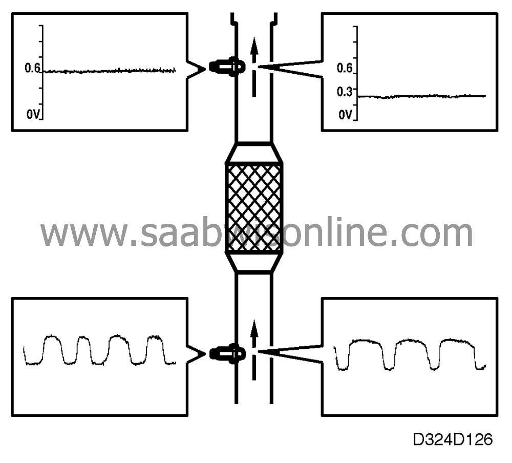
If the voltage is 0.3 V, for instance, the engine will run slightly lean. The closed loop system will then be corrected so that the fuel-air mixture is rich for a longer time than it is lean, resulting in an increase of the sensor voltage after the three way catalytic converter.
| Important | ||
|
The oxygen sensor obtains reference oxygen from the ambient air via the connecting cables. For this reason, neither contact cleaner nor grease should be used on the sensor connector contacts. |
||
