PRE-RELEASE
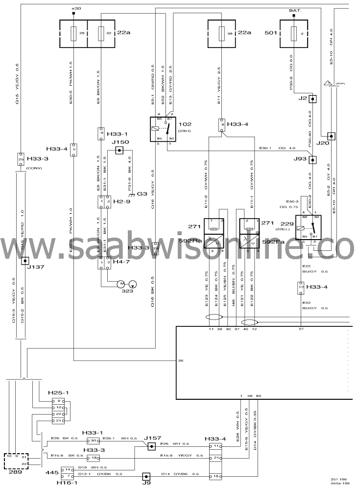
Wiring diagram, Motronic 4.1(I)
| Wiring diagram, Motronic 4.1(I) |
| List of components |
|
5
|
Ignition coil
|
|
6
|
Distributor
|
|
22A
|
Main fuse board, dashboard
|
|
MAXI
|
Maxi fuse
|
|
102
|
Relay, fuel pump. In main fuse box under the
dashboard. Position 22B:I (LHD) and 22B:F (RHD).
|
|
156
|
Relay, A/C compressor. In the main fuse box in the
engine bay (location 342B:J).
|
|
157
|
Spark plugs
|
|
166
|
Pressure switch, 3-stage, A/C. On the receiver
between the front grille and radiator fan.
|
|
171
|
Antifrost thermostat, A/C and ACC. Behind ashtray
in centre console.
|
|
178a
|
Knock sensor (4-cyl.). In the engine block under the
intake manifold.
|
|
202
|
Coolant temperature sensor, engine management
system. In the intake manifold, top left-hand side of engine.
|
|
203
|
Throttle position sensor. On the throttle
body.
|
|
205
|
Mass air flow sensor. On intake manifold between
air cleaner and throttle body.
|
|
206a
|
Injector, cylinder 1. On the top of the intake
manifold.
|
|
206b
|
Injector, cylinder 2. On the top of the intake
manifold.
|
|
206c
|
Injector, cylinder 3. On the top of the intake
manifold.
|
|
206d
|
Injector, cylinder 4. On the top of the intake
manifold.
|
|
229
|
Main relay, engine management
system
|
|
271
|
Heating element, oxygen sensor
|
|
272
|
IAC valve, idling speed. Centrally located beside the
intake manifold.
|
|
289
|
Anti-theft alarm control module. Under the LH front
seat.
|
|
321
|
Evaporative emission canister. In the engine bay, on
the right-hand side.
|
|
322
|
Connector, coding. Beside the Motronic control
module.
|
|
323
|
Motor, fuel pump with integrated feed
pump
|
|
324
|
Relay, secondary air injection pump
|
|
325
|
Secondary air injection control valve
|
|
326
|
Motor, secondary air injection pump
|
|
342A
|
Main fuse board, engine bay. In the main fuse
box.
|
|
345
|
Crankshaft position sensor
|
|
445
|
Data link connector. 16-pin. Under the dashboard by
the steering wheel.
|
|
500
|
Control module, ICE. On top of the relay holder
adjacent to the steering column.
|
|
502
|
TCM control module. Behind the glove box on the
bulkhead partition.
|
|
540b
|
Main instrument display panel, high specification. In
the dashboard.
|
|
547
|
ABS control module. Integrated into the hydraulic
unit in the engine bay.
|
|
555
|
Camshaft position sensor. In the
distributor.
|
|
584
|
Relay, secondary air injection control
valve
|
|
586
|
Control module, Motronic 4.1
|
|
590
|
Sensor, rough road
|
|
592Fa
|
Front heated oxygen sensor, 4-cyl, OBD
II
|
|
592Ra
|
Rear heated oxygen sensor, 4-cyl, OBD II
|
2-pin connector
|
H2-9
|
Connector, under the rear seat adjacent to the fuel
pump.
|
4-pin connectors
|
H4-7
|
Connector, under the rear seat adjacent to the fuel
pump.
|
6-pin connector
|
H6-7
|
Crimped connection in branch to Maxi fuse 2 in fuse box
342a.
|
10-pin connectors
|
H10-2
|
Connector, on a bracket below the left-hand A
pillar.
|
16-pin connector
|
H16-1
|
Connector, under the dashboard beside the steering
column.
|
25-pin connector
|
H25-1
|
Under the driver's seat.
|
33-pin connectors
|
H33-1
|
Connector (blue), on a bracket below the left-hand A
pillar.
|
|
H33-2
|
Connector (black), on a bracket below the left-hand
A pillar.
|
|
H33-3
|
Connector (grey), on a bracket below the left-hand A
pillar.
|
|
H33-4
|
Connector, on the bulkhead partition behind the
glove box.
|
|
H33-5
|
Connector, on the bulkhead partition behind the glove
box.
|
Grounding points
|
G3
|
Grounding point, luggage compartment, under LH
rear light cluster.
|
|
G7P
|
Grounding point, engine (power), on sheet metal
bracket at rear of engine.
|
|
G7S
|
Grounding point, engine (signal), on sheet metal
bracket at rear of engine.
|
|
G30
|
Grounding point, left-hand structural member,
behind the battery.
|
|
|
|
|
|
|
|
|
|
|
|
|
