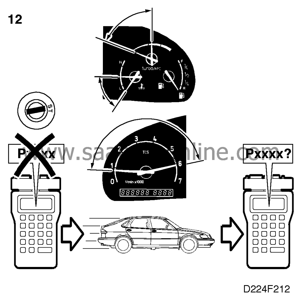
P0301,P0302, P0303, P0304
Symptom: The CHECK ENGINE lamp (MIL) is on or flashing. Uneven running when
misfiring. Possibly other diagnostic trouble codes.
|
|
P0301
,
P0302
,
P0303
,
P0304
|
Misfiring in cylinder 1, 2, 3 or 4
Symptom of fault
The CHECK ENGINE lamp (MIL) is on or flashing. Uneven running when
misfiring. Possibly other diagnostic trouble codes.
Conditions
An engine load and speed dependent matrix in the electronic control module's
memory specifies how large a proportion of misfires is required for exhaust emissions to
reach prohibited limits or for the three way catalytic converter to be damaged. If the number of
misfires exceeds the matrix value, a diagnostic trouble code will be generated. If misfiring
occurs in more than one cylinder, the cylinder in question accounts for more than 95%% of the
misfires.
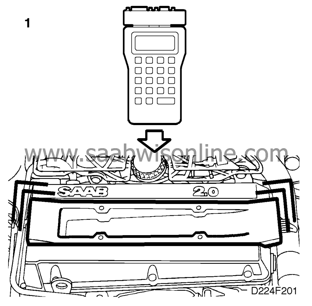
Diagnostic help
The injectors and the corresponding ignition coils can be activated using an ISAT scan
tool.
|
-
|
Select
"INJECTORS" and
"IGNITION COILS".
|
Then select the cylinder concerned in the appropriate submenu. Momentary
misfiring can be ascertained using an ISAT scan tool.
|
-
|
Select
"READ FUNCTIONS".
|
|
-
|
Select
"MISFIRING CYLINDER 1".
|
Other cylinders can also be selected.
Checking the wiring. Intermittent faults may occur as a result of occasional short circuits
and breaks in the wiring. Jiggle the leads and in-line connectors at several places and in
different directions to reveal faults in the wiring harness. Observe the multimeter, ISAT scan
tool or test lamp while carrying out this check.
Diagnostic procedure
1. Check the operation of the ignition coil concerned
|
-
|
Connect an ISAT scan tool.
|
|
-
|
Ignition switch in ON position.
|
|
-
|
Select
"IGNITION COILS"
|
|
-
|
Select
"IGNITION CYL 1", "CYL 2", "CYL 3" or "CYL 4".
|
|
-
|
Select
the cylinder concerned.
|
Activation of an ignition coil takes place for 10 seconds at 200 Hz. If a longer
activation time is required, the command must be repeated.
|
-
|
Listen for the sound of each
ignition coil operating.
|
Is the ignition coil in question operating?
Proceed to point 4.
Continue with point 2.
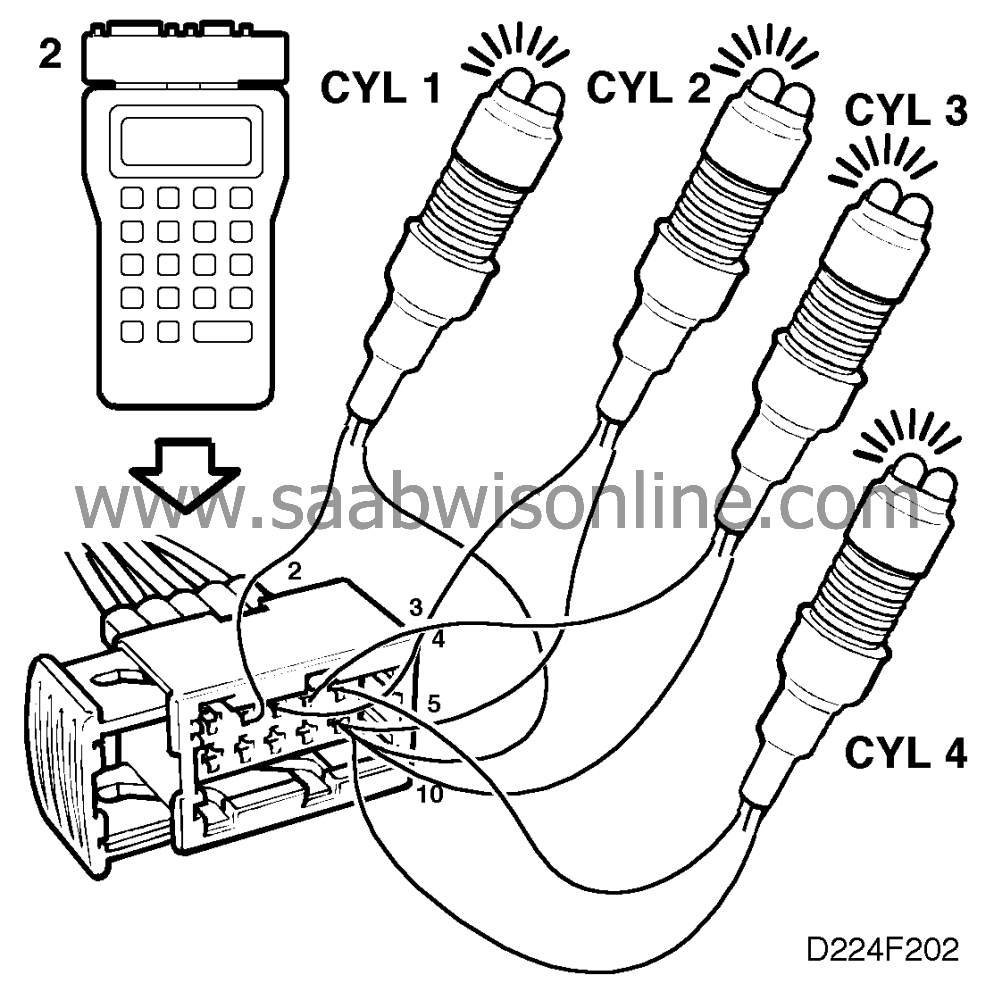
2. Check the trigger lead of the ignition coil
concerned
|
-
|
Unplug the ignition discharge
module's 10-pin connector.
|
|
-
|
Ignition switch in ON
position.
|
|
-
|
Connect the test lamp to pin 10
and the trigger lead of the ignition coil in question, see table below.
|
|
-
|
Then activate the ignition coil
concerned by means of an ISAT scan tool command.
Trigger lead, cylinder No.
|
10-pin connector, pin No.
|
1
|
2
|
2
|
3
|
3
|
4
|
4
|
5
|
The test lamp should light up for 10 seconds, during which time it should flicker
(go out repeatedly for extremely brief periods). In the event of uncertainty, repeat the
command.
|
Does the test lamp light up and start flickering?
Change the ignition discharge module and proceed to point 12.
The test lamp does not light up or remains on continuously. Continue with point
3.
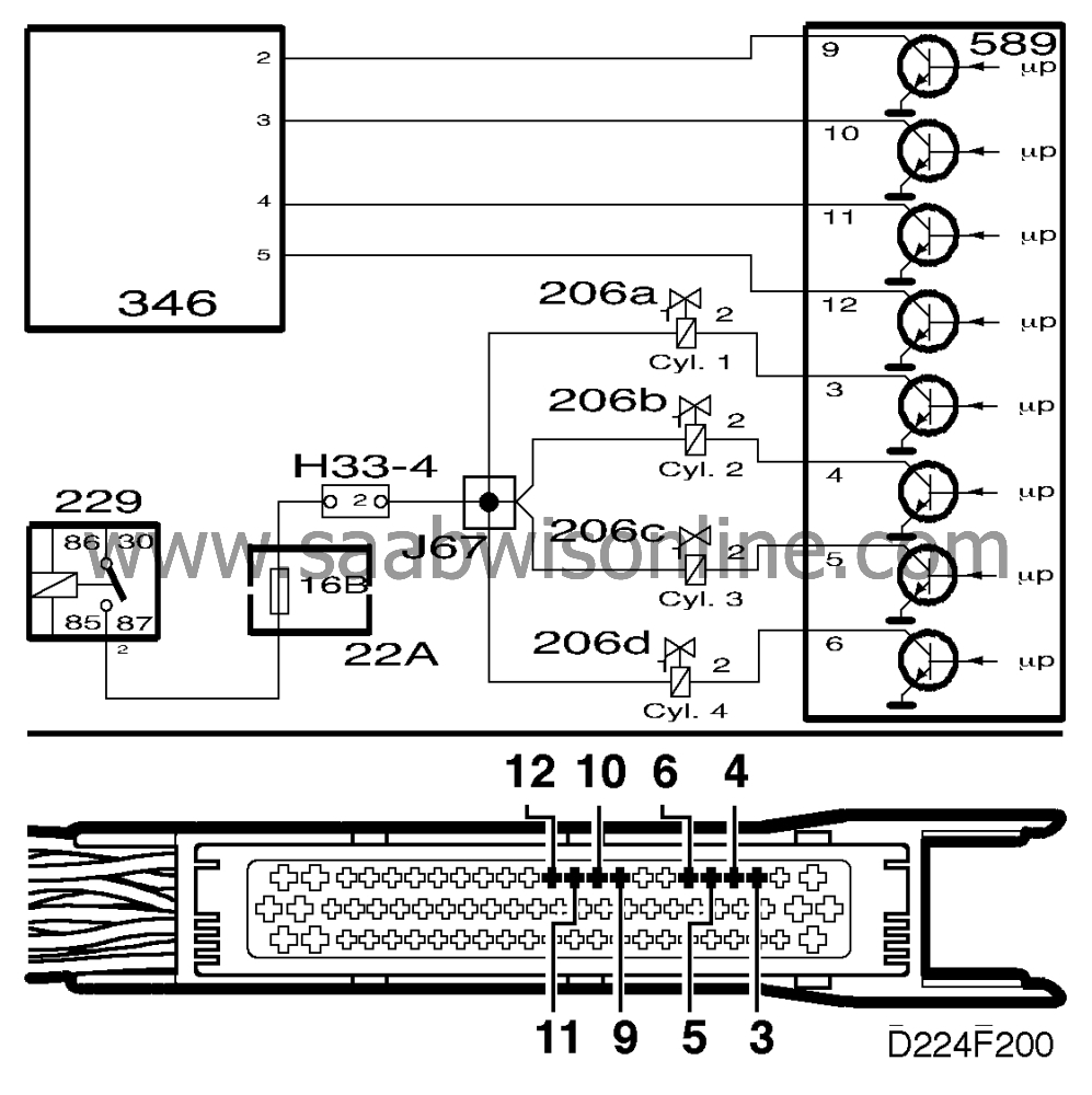
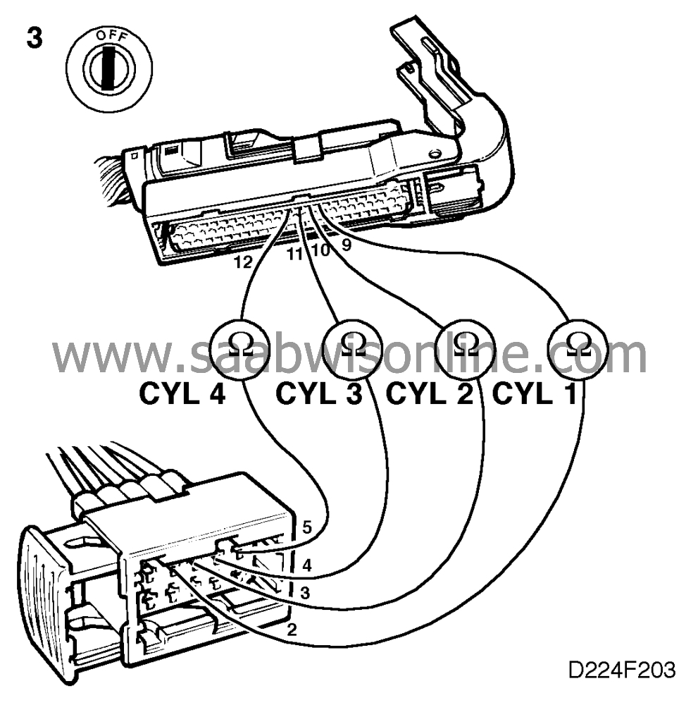
3. Check the trigger lead in
question
|
-
|
Check the trigger lead in question
for continuity, see table below.
|
|
-
|
Check the lead for
continuity/shorting.
Trigger lead, cylinder
No.
|
10-pin connector, pin
No.
|
Control module, pin No.
|
1
|
2
|
9
|
2
|
3
|
10
|
3
|
4
|
11
|
4
|
5
|
12
|
|
Is the lead OK?
Continue with point 4.
Rectify the fault and proceed to point 12.
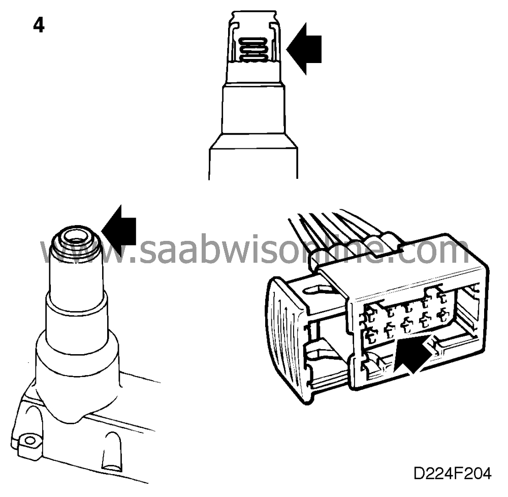
4. Check the condition of the ignition discharge
module
|
-
|
Remove the ignition discharge
module from the camshaft cover.
|
|
|
•
|
that the four rubber seals for the
spark plugs are in good condition.
|
|
|
•
|
that no contact spring for the spark plugs is missing or that spring travel is
inadequate.
|
|
|
•
|
the connector for moisture and corrosion
|
Is the ignition discharge module OK?
Continue with point 5.
Rectify the fault and proceed to point 5.
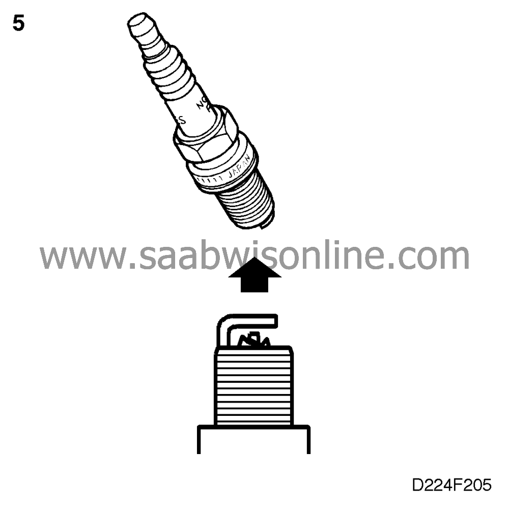
5. Check the spark plugs
|
-
|
Remove the spark plugs and check
their condition visually.
|
Are the plugs OK?
Continue with point 6.
The electrode gap is wider than 1.4 mm or is otherwise obviously incorrect.
Change the spark plugs and proceed to point 12.
 Warning
|
|
The electronic ignition system generates up to 40,000 Volts. Such voltages can prove
fatal to people with weak hearts or those who are fitted with a pacemaker. All due caution
should therefore be observed when carrying out any work involving the ignition
system.
|
|
|
|
|
|
|
Important
|
|
The ignition discharge module must be positioned with the ignition coils facing down
during the test so that the transformer oil will provide good insulation in the high-voltage part of
the ignition coils.
|
|
|
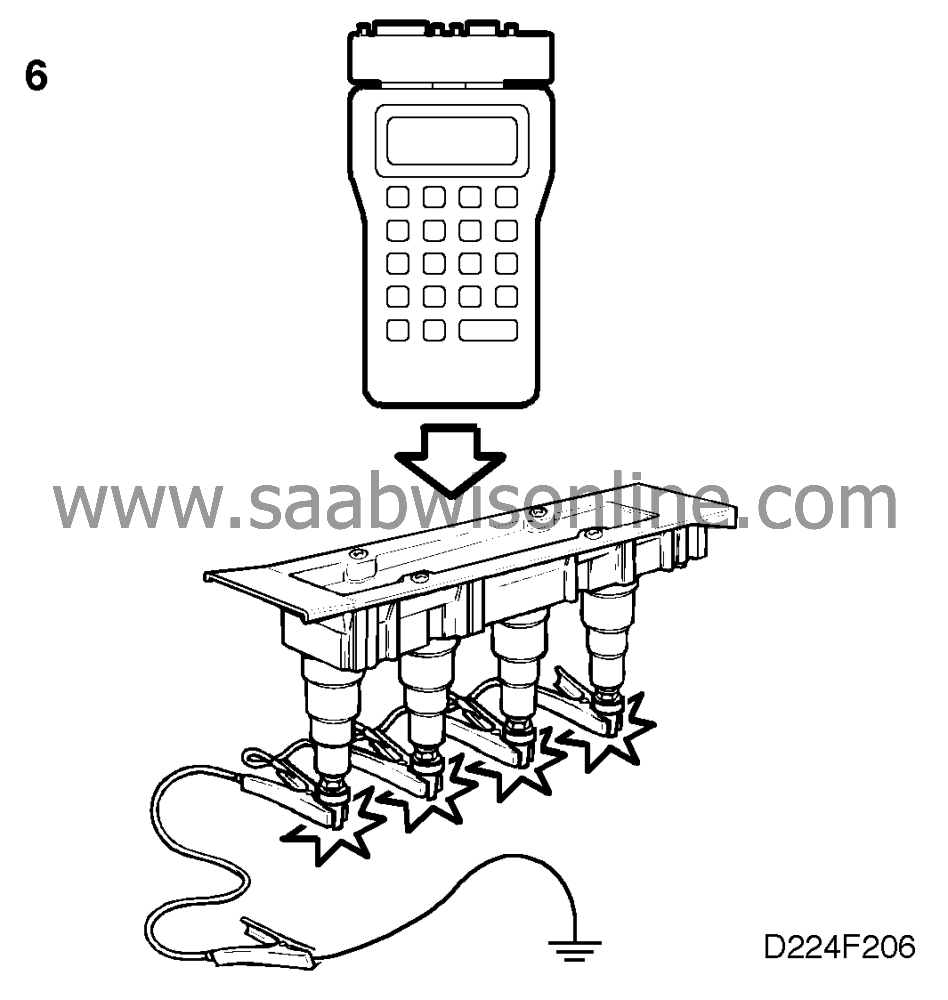
6. Check the operation of the ignition discharge
module
|
-
|
Fit a test spark plug (part No. 86 11
386) in the relevant spark plug socket.
|
|
-
|
Ground the plug using test cable
86 10 867.
|
|
-
|
Ignition switch in ON position.
|
|
-
|
Activate the ignition coil concerned,
using the ISAT scan tool.
|
|
-
|
Check that the activated spark plug
produces a spark.
|
Is a spark produced?
Continue with point 7.
Change the ignition discharge module and proceed to point 12.
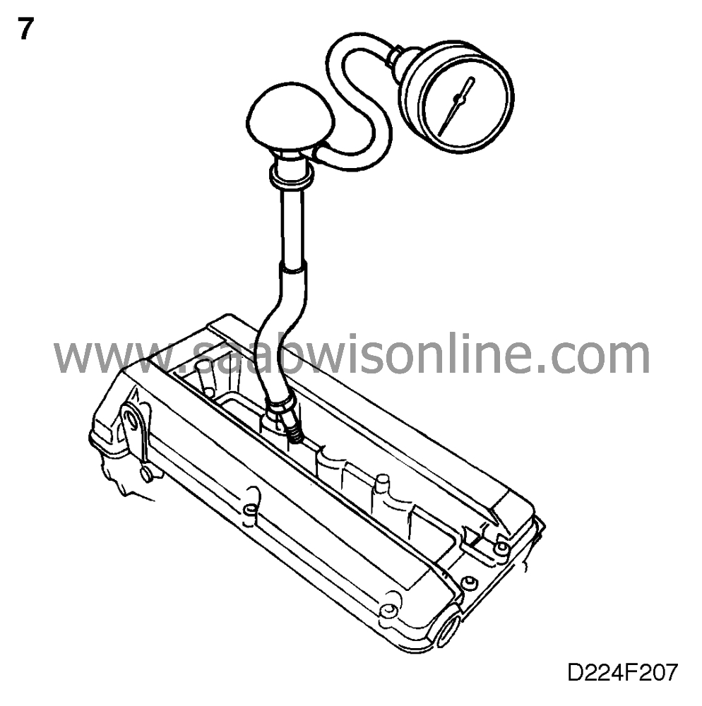
7. Check the compression
|
-
|
Check the compression of each
cylinder.
|
Is compression OK?
Change all spark plugs and continue with point 8.
Continue fault diagnosis as described in Service Manual 2:1 "Basic
engine".
8. Check the power supply (B+) of the injector
concerned
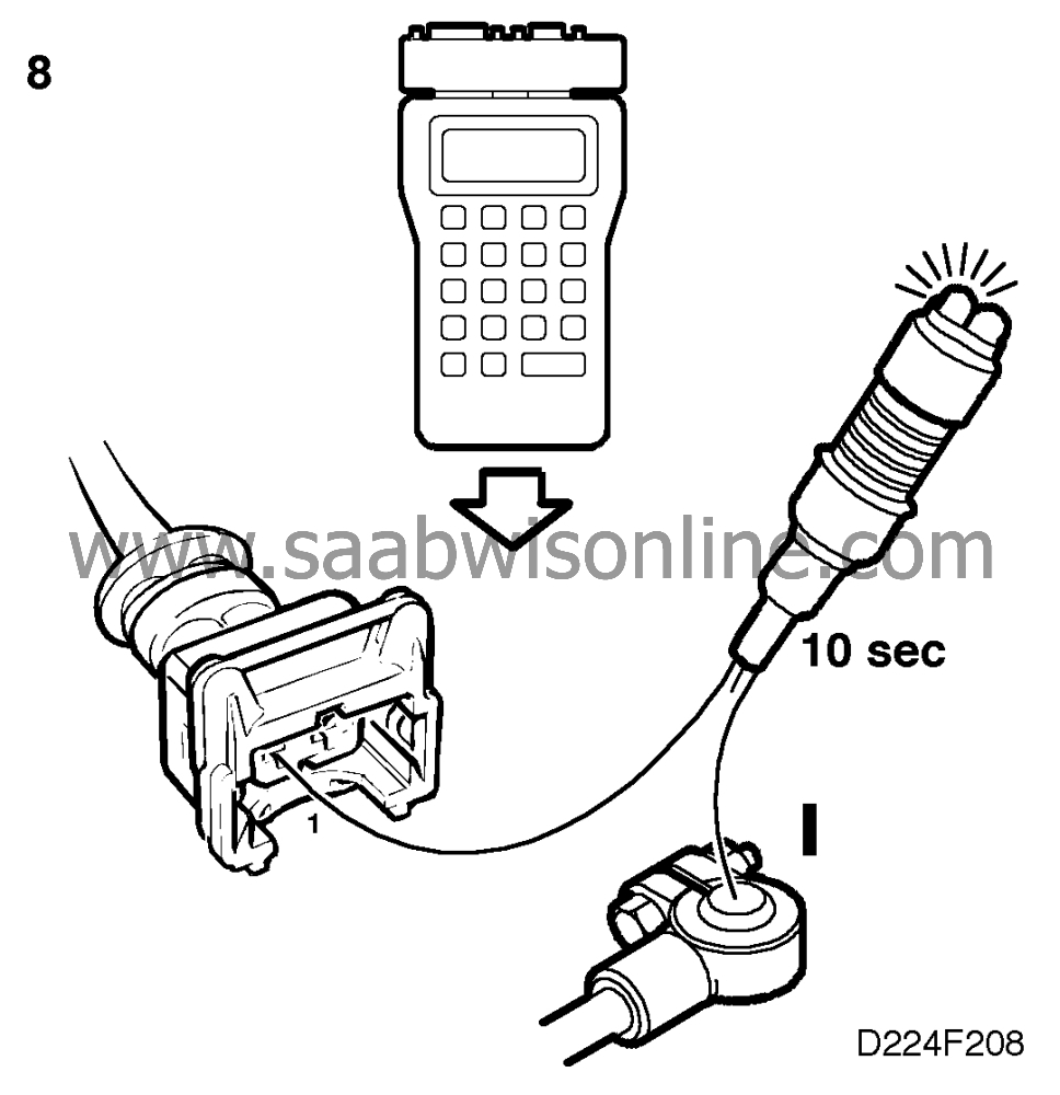
|
-
|
Check the voltage by connecting
the test lamp to pin 1 of the relevant injector's connector and B-.
|
|
-
|
Connect an ISAT scan
tool.
|
|
-
|
Select "INJECTOR CYL 1", "CYL
2", "CYL 3" or "CYL 4".
|
The test lamp should light up for 10 seconds during activation.
Is the test lamp on?
Continue with point 9.
The fault is in the lead between pin 1 and crimped connection J67. Rectify the
fault and proceed to point 12.
9. Check the relevant injector's control
module output
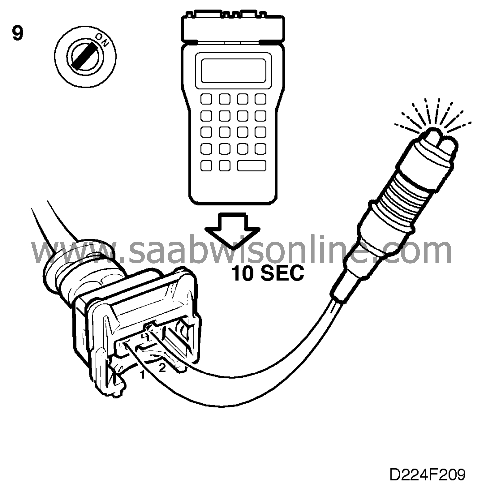
|
-
|
Unplug the relevant
injector's connector.
|
|
-
|
Connect the test lamp to pins 1 and
2 of the injector's connector.
|
|
-
|
Ignition switch in the ON position.
|
|
-
|
Activate the relevant injector using
the ISAT scan tool and the command
"INJECTOR CYL 1", "CYL 2", "CYL 3" or "CYL 4".
|
The test lamp should flash at a frequency of 10 Hz for 10 seconds. Repeat the
command in the event of uncertainty.
Does the test lamp flash?
Continue with point 10.
The test lamp flashes or remains on continuously. Check and, if necessary,
rectify the lead between pin 2 and the relevant electronic control module output. If the lead is
OK, proceed to point 12.
10. Check the resistance of the relevant injector
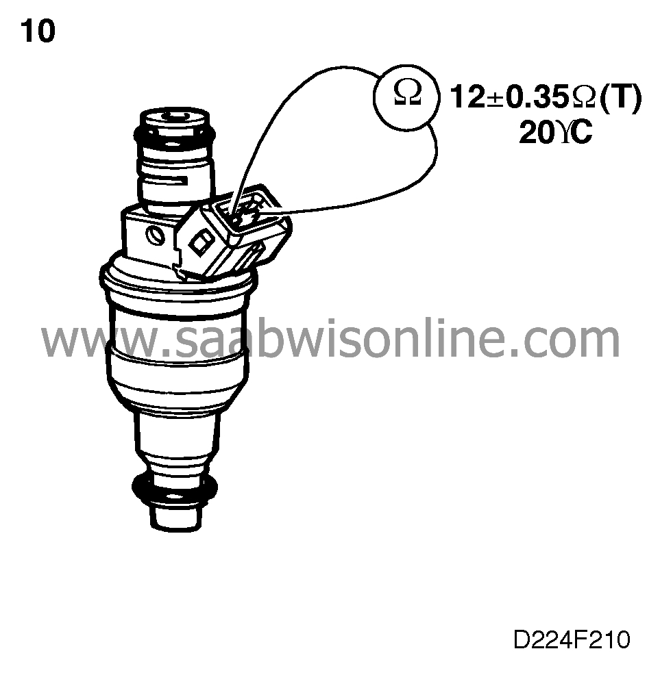
|
-
|
Take a resistance reading across
pins 1 and 2 of the relevant injector's connector. Nominal resistance is:
12±0.35 ohms at 20°C (68°F).
|
Is the resistance reading OK?
Continue with point 11.
Change the injector and proceed to point 12.
11. Check the relevant injector's fuel
delivery flow
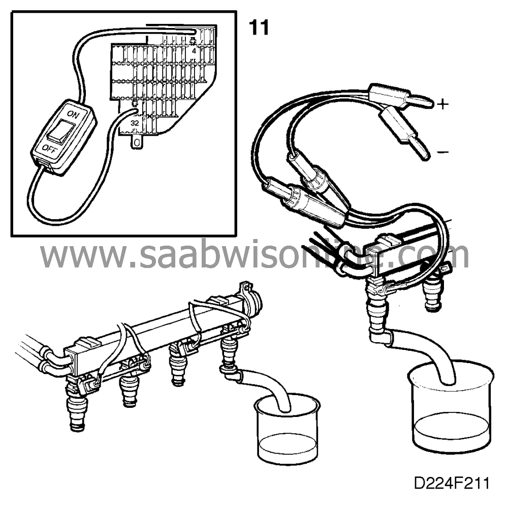
|
-
|
Measure the delivery flow. See
 .
.
|
Is the delivery flow OK?
Continue with point 12.
Change the injector and proceed to point 12.
12. Final check
|
-
|
Clear the diagnostic trouble
code.
|
|
-
|
Implementation of driving cycle:
Drive the car at different engine rpm and varying loads, especially at high revs, while the
engine is warming up.
|
|
-
|
Evaluation of driving cycle: Check
whether the diagnostic trouble code has recurred.
|
Has the diagnostic trouble code recurred?
Proceed to
.
The remedial measure taken was correct.
