PRE-RELEASE
Test readings, control module connections
| Test readings, control module connections |
| Scope |
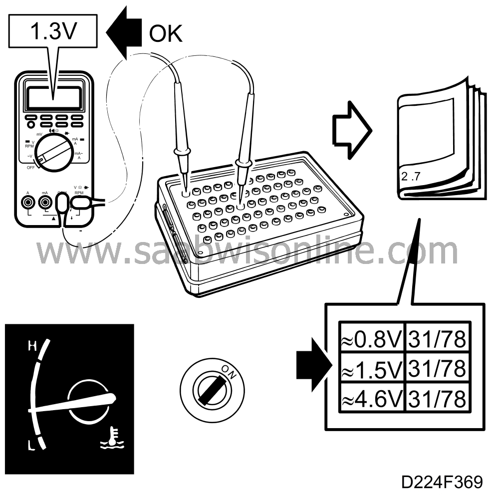
Test readings and directions for measuring signals and signal levels on the Trionic control module are given in the following pages.
| Some important points to remember: |
| • |
Readings should be taken with a
Breakout Box (BOB) connected between the control module and the control module's
connector.
|
|
| • |
Several voltage levels should be regarded as guiding values. Your common
sense should tell you whether a reading is correct or not.
|
|
| • |
If any test reading is obviously incorrect, use the wiring diagram to trace the
leads, connectors or components which you consider ought to be checked more thoroughly.
|
|
| • |
The pages referred to in the table contain a description of the relevant
signal's function and a fault diagnosis schedule with detailed, step-by-step instructions
explaining the diagnostic procedure to be followed.
|
|
| • |
All test readings are for a warmed-up engine.
|
|
| • |
Unless otherwise stated, the ignition should be switched on.
|
|
| • |
The test readings are in respect of a calibrated FLUKE 88/97.
|
|
>= greater than; < = less than; » = approximately equal to; ∼ = alternating current Pins without further comments are not used. (LP: LOGIC PROBE P = select pulse; p = visible pulses.)
|
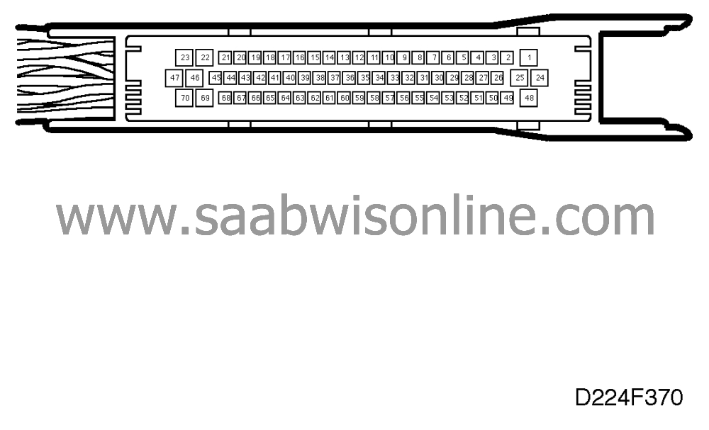
Pin
|
Colour
|
Component/Function
|
In/Out
|
Test
conditions
|
Across + -
|
Test
reading
|
|
1
|
PK/WH
|
+30
|
in
|
900+50 rpm
|
B+ to 1
|
<0.5 V
|
|
2
|
GN/BK
|
Boost pressure control valve
|
out
|
900 ± 50 rpm
|
2 - 25
|
90 Hz
17.5%%
(-) 1.9 ms
(-) (LP HI LO)
|
|
3
|
GN/WH
|
Injector 1
|
out
|
900 ± 50 rpm
|
3 - 25
|
7.5 Hz
2.5-4.5 ms (-)
(LP
HI
LOp)
|
|
4
|
BU/WH
|
Injector 2
|
out
|
900 ± 50 rpm
|
4 - 25
|
7.5 Hz
2.5-4.5 ms (-)
(LP
HI
LOp)
|
|
5
|
VT/WH
|
Injector 3
|
out
|
900 ± 50 rpm
|
5 - 25
|
7.5 Hz
2.5-4.5 ms (-)
(LP
HI LOp)
|
|
6
|
GY/WH
|
Injector 4
|
out
|
900 ± 50 rpm
|
6 - 25
|
7.5 Hz
2.5-4.5 ms (-)
(LP
HI LOp)
|
|
7
|
|
|
|
|
|
|
|
8
|
|
|
|
|
|
|
> = greater than; < = less than; = » approximately equal to; ∼ = alternating current
|
Pin
|
Colour
|
Component/Function
|
In/Out
|
Test
conditions
|
Across + -
|
Test
reading
|
|
9
|
OG/BK
|
Trigger 1
|
out
|
900 ± 50 rpm
|
9 - 25
|
7.5 Hz
8.3 %% (-)
11 ms (-)
(LP
HI LOp)
|
|
10
|
GN/YE
|
Trigger 2
|
out
|
900 ± 50 rpm
|
10 - 25
|
7.5 Hz
8.3 %% (-)
11 ms (-)
(LP
HI LOp)
|
|
11
|
BU/RD
|
Trigger 3
|
out
|
900 ± 50 rpm
|
11 - 25
|
7.5 Hz
8.3 %% (-)
11 ms (-)
(LP
HI LOp)
|
|
12
|
GY/RD
|
Trigger 4
|
out
|
900 ± 50 rpm
|
12 - 25
|
7.5 Hz
8.3 %% (-)
11 ms (-)
(LP
HI LOp)
|
|
13
|
OG/ WH
|
Engine torque
limitation
|
in
|
|
13 - 25
|
B+
|
|
Shifting
|
13 - 25
|
0 V
|
||||
|
14
|
BK/WH
|
DRIVE
|
in
|
P, N
|
14 - 25
|
0 V
|
|
R, D, 1, 2, 3
|
14 - 25
|
B+
|
||||
|
15
|
VT
|
Switch, brake
lights
|
in
|
brake pedal not
depressed
|
15 - 25
|
0 V
|
|
brake pedal depressed
|
15 - 25
|
B+
|
||||
|
16
|
|
|
|
|
|
|
|
17
|
YE/BN
|
Combustion cyl. 1+2
|
in
|
900 ± 50 rpm
|
17 - 25
|
15-30 Hz
(LP
LO HIp)
|
|
18
|
BN/RD
|
Combustion cyl. 3+4
|
in
|
900 ± 50 rpm
|
18 - 25
|
15-30 Hz
(LP
LO HIp)
|
|
19
|
|
|
|
|
|
|
|
20
|
PK
|
Manifold absolute pressure
signal
|
out
|
|
20 - 67
|
1.0 V *)
|
|
21
|
BU
|
M96: EVAP canister purge valve
Diagnosis
|
in
|
900 ± 50 rpm, warm engine
and >1 min. since starting.
|
21 - 25
|
1.3 V
8 Hz
10%% (-)
12 ms (-)
(
HI
LOp)
|
|
BU
|
M96 1/2: Tank pressure
sensor
|
in
|
Undo the tank filler cap.
|
21 - 25
|
0 kPa =
2.5 V
see also technical data
|
|
|
22
|
BU/BN
|
Manifold absolute pressure sensor
|
in
|
|
22 - 67
|
100 kPa =
1.9 V
see also technical data
|
*) A somewhat lower reading may be obtained at high altitudes.
> = greater than; < = less than; = » approximately equal to; ∼ = alternating current
|
Pin
|
Colour
|
Component/Function
|
In/Out
|
Test
conditions
|
Across + -
|
Test
reading
|
|
23
|
GN
|
Front heated oxygen sensor (oxygen
sensor 1)
|
in
|
900 ± 50 rpm, warm engine
and >1 min. since starting
|
23 - 47
|
0.1-0.9 V
|
|
24
|
BK
|
Main ground
|
in
|
900 ± 50 rpm
|
24 - B-
|
<0.1 V
|
|
25
|
BK
|
Main ground
|
in
|
900 ± 50 rpm
|
25 - B-
|
<0.1 V
|
|
26
|
BU
|
Boost pressure control
valve
|
out
|
1000-1500 rpm
|
1 - 26
|
2.3 V
|
|
1000-1500 rpm
|
|
90 Hz
17.5%% (-)
1.9 ms (-)
(LP P HI LO)
|
||||
|
27
|
M96: BU M96 1/2:
YE/GY
|
EVAP canister purge
valve
|
out
|
900 ± 50 rpm and engine
warm
|
27 - 25
|
1.3 V
8 Hz
10%% (-)
12 ms (-)
(
HI
LOp)
|
|
28
|
GN
|
Shut-off valve,
evaporative emission canister
|
out
|
900 ± 50 rpm
|
28 - 25
|
B+
|
|
In connection with EVAP
diagnostics.
|
28 - 25
|
0 V
|
||||
|
29
|
|
|
|
|
|
|
|
30
|
|
|
|
|
|
|
|
31
|
BU/GY
|
Main
relay
|
out
|
|
31 - 25
|
B+
|
|
start the engine
|
31 - 25
|
<0.5 V
|
||||
|
32
|
YE/GN
|
CHECK
ENGINE
|
out
|
|
32 - 25
|
<0.5 V
|
|
engine running and CHECK ENGINE
lamp (MIL) out
|
32 - 25
|
B+
|
||||
|
33
|
GY/BK
|
Diagnosis
|
in/out
|
ISAT scan tool not
connected
|
33 - 25
|
»
6.5 V
|
|
ISAT scan tool
connected
|
33 - 25
|
B+
|
||||
|
34
|
|
|
|
|
|
|
|
35
|
|
|
|
|
|
|
|
36
|
BU/GN
|
Cruise
Control
|
in
|
|
36 - 25
|
»
10 V
|
|
CC active
|
36 - 25
|
<0.5 V
|
||||
|
37
|
|
|
|
|
|
|
> = greater than; < = less than; = » approximately equal to; ∼ = alternating current
|
Pin
|
Colour
|
Component/Function
|
In/Out
|
Test
conditions
|
Across + -
|
Test
reading
|
|
38
|
YE
|
Low fuel
level
|
in
|
low fuel warning lamp in main
instrument display panel on
|
38 - 25
|
<0.5 V
|
|
low fuel warning lamp in main
instrument display panel out
|
38 - 25
|
B+
|
||||
|
39
|
PK/BK
|
Vehicle speed signal
|
in
|
raise RH front wheel, rotate 1/2
turn/sec.
|
39 - 25
|
15 Hz
50%%
(LP HIp LOp)
|
|
40
|
|
|
|
|
|
|
|
41
|
YE
|
Crankshaft position
sensor
|
in
|
900 ± 50 rpm
|
41 - 67
|
5-10 V∼
»
870 Hz (LP HI LO)
|
|
42
|
WH/BK
|
Throttle position sensor
|
out
|
|
42 - 67
|
5 V
|
|
43
|
GY
|
Pressure sensor
|
out
|
|
43 - 67
|
5 V
|
|
44
|
OG
|
Knock signal
|
in
|
900 ± 50 rpm
|
44 - 25
|
50-100 mV∼ (LP P LO)
|
|
45
|
GN/BN
|
Throttle position sensor
|
in
|
|
45 - 67
|
idling
»
0.5 V see also technical data
|
|
46
|
WH/BK
|
Intake air temperature
sensor
|
in
|
40°C (104°F)
|
46 - 67
|
1.5 V
see also technical data
|
|
47
|
BK
|
Heated oxygen sensor, reference
ground
|
in
|
900 ± 50 rpm
|
47 - 67
|
0-1 V
|
|
48
|
PK/WH
|
+30
|
in
|
900 ± 50 rpm
|
B+ - 48
|
<0.5 V
|
|
49
|
BU/VT
|
Idle air control valve
|
out
|
A/C and all electrical equipment
switched off
|
49 - 25
|
500 Hz
25-50%%
0.5-1.0 ms
(LP HI LO)
|
|
50
|
BK/WH
|
Front heated oxygen
sensor, heating
|
out
|
900 ± 50 rpm
|
50 - 25
|
»
0.5 V
|
|
remove fuse 38
|
50 - 25
|
0 V
|
||||
|
51
|
BK/WH
|
Rear heated oxygen
sensor, heating
|
out
|
900 ± 50 rpm, coolant temp
>50°C (122°F)
|
51 - 25
|
»
0.5 V
|
|
remove fuse 38
|
51 - 25
|
0 V
|
> = greater than; < = less than; = » approximately equal to; ∼ = alternating current
|
Pin
|
Colour
|
Component/Function
|
In/Out
|
Test
conditions
|
Across + -
|
Test
reading
|
|
52
|
|
Vacuum pump, brake
system
|
out
|
P, N
|
52 - 25
|
B+
|
|
R, D, 1, 2, 3
|
52 - 25
|
<0.5 V
|
||||
|
53
|
|
|
|
|
|
|
|
54
|
RD/WH
|
A/C out
|
out
|
900 ± 50 rpm, A/C
On
|
54 - 25
|
<0.5 V
|
|
900 ± 50 rpm, A/C
OFF
|
54 - 25
|
B+
|
||||
|
55
|
BU/YE
|
SHIFT
UP
|
out
|
when ignition switch turned to
ON
|
55 - 25
|
<0.5 V
|
|
After 3 sec.
|
55 - 25
|
B+
|
||||
|
56
|
WH
|
Fuel pump
relay
|
out
|
|
56 - 25
|
B+
|
|
900 ± 50 rpm
|
56 - 25
|
<0.5 V
|
||||
|
57
|
GN/OG
|
Throttle position signal
|
out
|
900 ± 50 rpm
|
57 - 25
|
100 Hz 9 %% (+) 0.9 ms (+) (LP
LO HI)
|
|
58
|
GN/RD
|
Engine speed signal
|
out
|
900 ± 50 rpm
|
58 - 25
|
30 Hz
(LP
LO HIp)
|
|
59
|
GN/GY
|
A/C in
|
in
|
900 ± 50 rpm, A/C
On
|
59 - 25
|
B+
|
|
900 ± 50 rpm, A/C
OFF
|
59 - 25
|
0 V
|
||||
|
60
|
YE/GY
|
+15
|
in
|
|
B+ - 60
|
<0.5 V
|
|
61
|
BU/GN
|
CHECK ENGINE
request
|
in
|
ON
|
61 - 25
|
B+/0 V
(2 Hz)
(LP HIp LOp)
|
|
OFF
|
61 - 25
|
0 V
|
||||
|
62
|
BK/WH
|
For production only
|
|
|
|
|
|
63
|
BN
|
For production only
|
|
|
|
|
|
64
|
|
|
|
|
|
|
|
65
|
YE
|
For production only
|
|
|
|
|
|
66
|
BK
|
Reference ground, engine coolant
temperature sensor
|
in
|
|
66 - 25
|
<0.05 V
|
|
67
|
BK
|
Sensor ground
|
out
|
|
67 - 25
|
<0.05 V
|
|
68
|
YE/WH
|
Engine coolant temperature
sensor
|
in
|
90°C (194°F)
|
68 - 66
|
0.41 V
see also technical data
|
|
69
|
|
|
|
|
|
|
|
70
|
GN
|
Rear heated oxygen sensor (oxygen sensor
2)
|
in
|
900 ± 50 rpm
|
70 - 47
|
0.1-0.9 V
|
