PRE-RELEASE
Alternator design
| Alternator design |
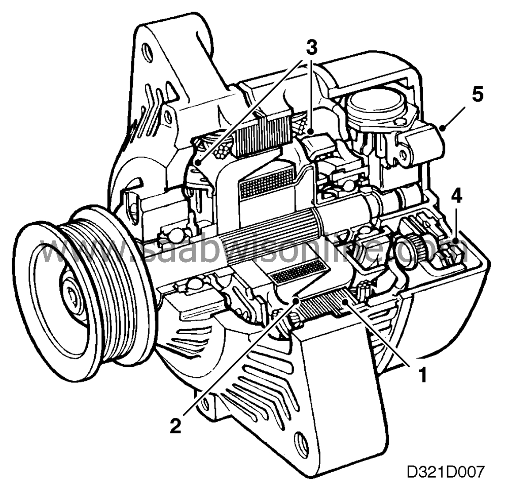
The alternator consists of the following components:
| 1. |
Stator
|
|
| 2. |
Rotor and slip-rings
|
|
| 3. |
Integral fans
|
|
| 4. |
Rectifier
|
|
| 5. |
Voltage regulator
|
|
The alternator has an external voltage regulator.
The alternator is driven by a poly-V belt from the crankshaft pulley and is accessible for service and removal.
When the engine is switched off, the battery is the source of electric current. The alternator acts as a "power station" when the engine is running and supplies all items of electrical equipment in the car with current.
| Stator |
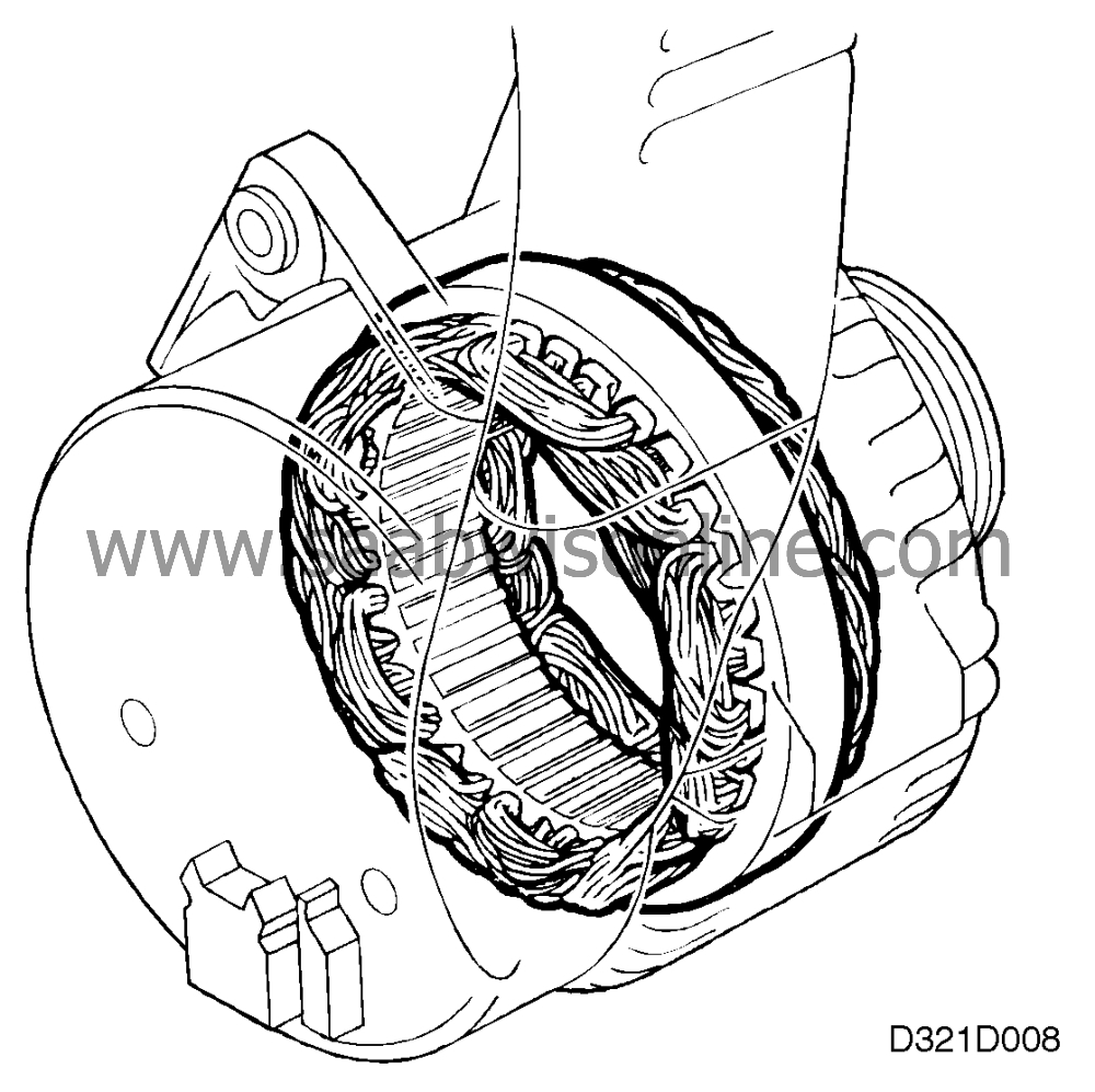
The stator is fixed and consists of grooved plates which are insulated from each other and pressed together to make a fixed assembly. The sinuous coils of the stator winding are fitted in the grooves.
They are star-connected with 120° spacing and produce a three-phase AC supply.
| Rotor and slip-rings |
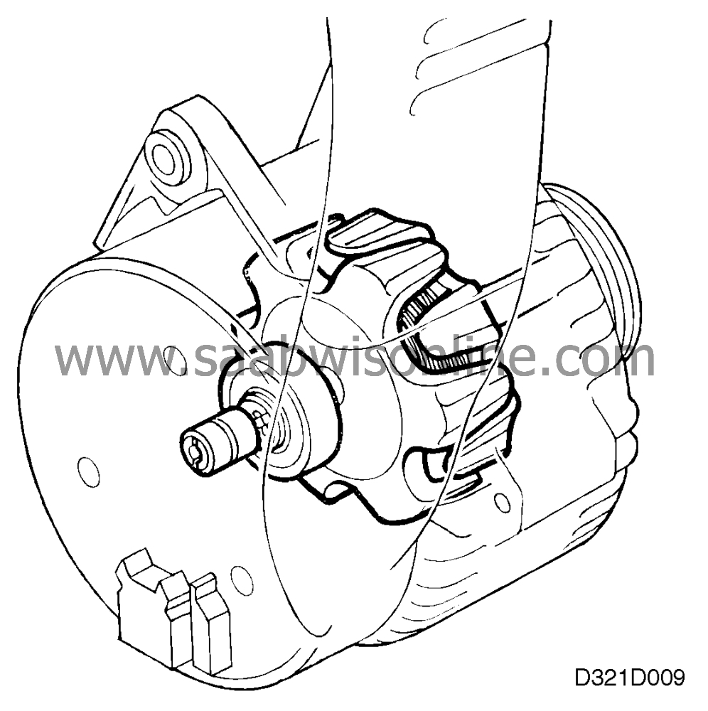
The rotor consists of two halves (claw-type poles) which mesh with each other. The two halves are a press fit on the rotor shaft and there are 12 claws in total on the rotor, i.e. 12 poles. One of the rotor halves then has six north poles and the other half six south poles.
The excitation winding is fixed on the rotor shaft between the claw-type pole halves.
The excitation winding consists of a circular coil which is surrounded by the claw-type poles.
A comparatively low excitation current is applied through the carbon brushes in contact with the slip rings.
| Integral fans |
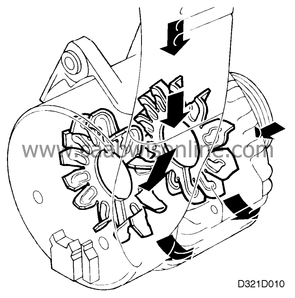
The heat generated in the alternator when it is in operation can damage the insulation, soldered joints and diodes.
The alternator has two integral fans which dissipate the heat.
The fans are driven by the rotor shaft. Cars equipped with a V6 engine also have an extra air intake to increase the flow of cooling air.
| Rectifier |
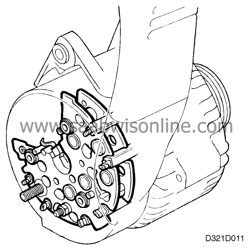
The alternating current (a.c.) produced by the alternator must be converted into direct current (d.c.) before it can be used in the car's electrical system. It is converted by means of six (four-cylinder engine) or twelve (V6 engine) zener diodes, two (4-cylinder) or four (V6) per phase winding.
If a phase is positive, the current from it flows through the positive diodes to B+. Conversely, if a phase is negative, the current from it flows through the negative diodes to D-.
| Voltage regulator |
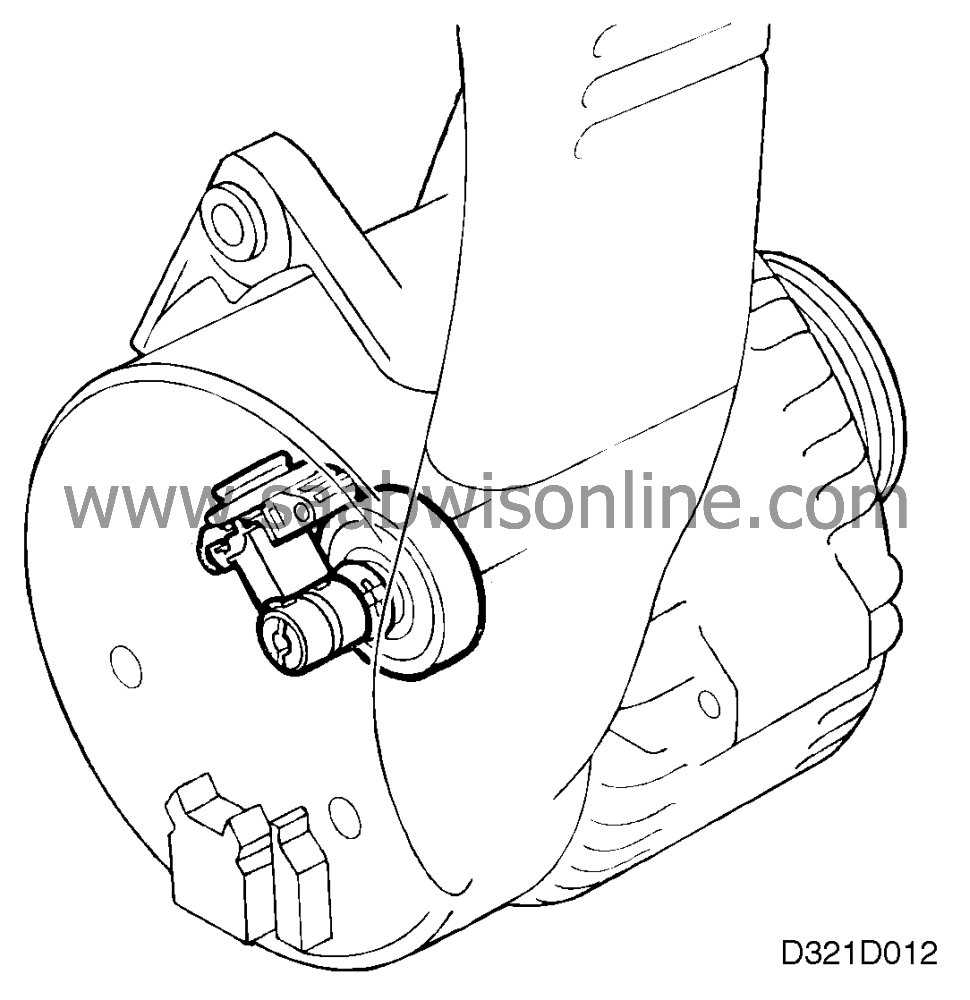
The purpose of the voltage regulator is to maintain the current from the alternator, whatever its speed and load demand, at a constant level regardless of engine rpm.
If the current generated exceeds the prescribed reference voltage (about 14 V), depending on the load, the voltage regulator will reduce or cut off the excitation current.
Generator excitation decreases and the voltage drops.
When the voltage has dropped below the reference level (approx. 14 V), excitation increases and with it also the alternator voltage until the reference level is again exceeded. This cycle is repeated continuously.
| Important points to bear in mind |
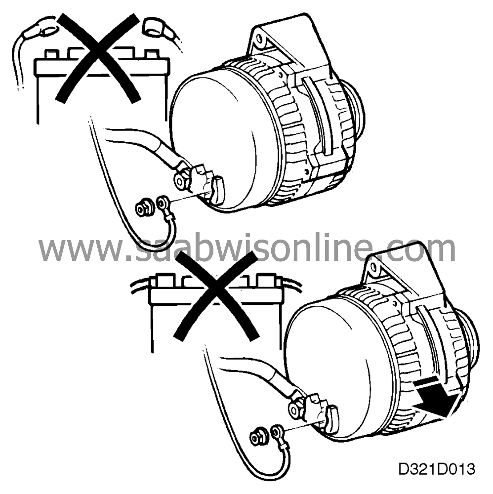
You must:
| • |
never
disconnect the battery while the alternator is
running;
|
|
| • |
never
remove the alternator while the battery is
connected;
|
|
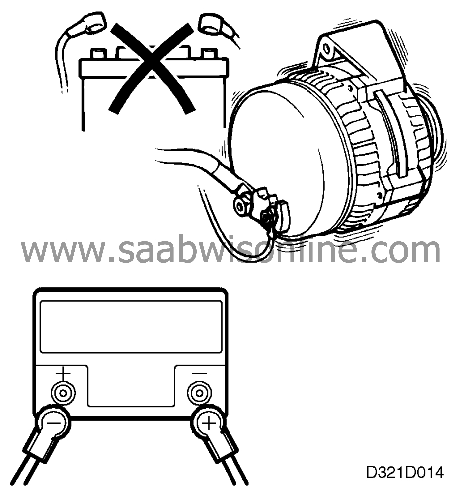
| • |
never
test the alternator in the car or on
a test bench
unless the battery is connected;
|
|
| • |
never
reverse the polarity of the battery (this may
result
in serious damage to the alternator).
Alternators should be overhauled and repaired only by specialist workshops. It is extremely important that they are dismantled and tested correctly, as even minor errors can lead to serious damage. For removing and testing the parts of the alternator, refer to Service Manual 3:1 "Electrical system, instruments"  for earlier model 900
or 9000 cars.
for earlier model 900
or 9000 cars.
|
||||||||||
