PRE-RELEASE
Alternator, general
| Alternator, general |
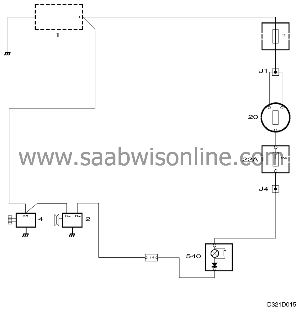
Components
| 1. |
Battery 1
|
|
| 2. |
Alternator 2
|
|
| 3. |
Starter motor 4
|
|
| 4. |
Ignition switch 20
|
|
| 5. |
Fuse holder 22A
|
|
| 6. |
Main instrument display panel with warning lamp 540
|
|
When the ignition switch is turned to the Drive or Start position (+15), the circuit is closed.
Current then flows from the ignition switch via the warning lamp to terminal D+ on the alternator. It continues through the rotor excitation winding and to ground via the voltage regulator.
Current flowing through the rotor generates a magnetic field round the rotor. When the engine is started and the rotor starts to rotate, the magnetic field will also rotate and generate an alternating current in the stator windings. This alternating current is rectified by the rectifier diodes and the resulting direct current is supplied to the battery via terminal B+.
The current from the stator windings also flows through the excitation diodes to the voltage regulator where it is used for controlling the output voltage. When the voltage rises above 14 V, the voltage regulator reduces the current flowing through the excitation winding.
This weakens the magnetic field as well as the alternating current generated in the stator windings.
The warning lamp is also affected by the voltage supplied by the stator windings via terminal D+ on the voltage regulator, so that the difference in voltage on each side of the lamp is equalized and the lamp goes out.
The lamp also indicates whether the alternator is charging.
| Internal circuitry |
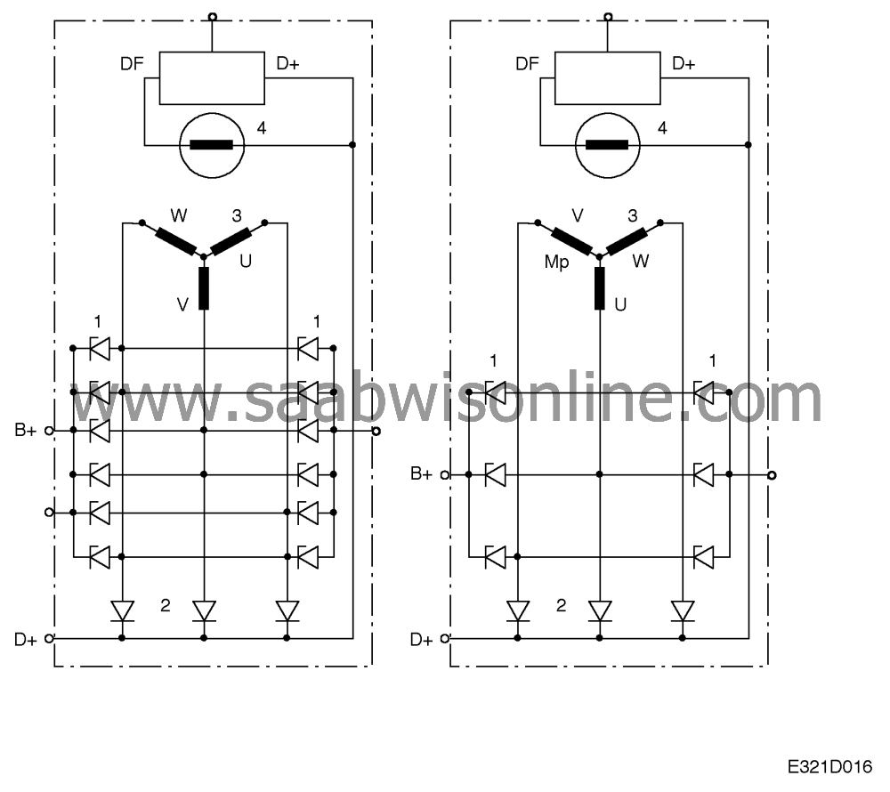
The alternator has a 12-pole rotor and six (four- cylinder engine) or 12 (V6 engine) zener diodes (1) for rectification.
An excitation diode is connected to each of the three stator windings (2).
The stator windings form three phases and are star- connected (3).
The six (four-cylinder engine) or twelve (V6 engine) rectifier diodes are connected in the form of an a.c. bridge circuit, i.e. three (4-cylinder) or six (V6) diodes are connected for normal polarity (anode to terminal) and three or six for reversed polarity (anode to ground).
According to the polarity, the diode holder is either insulated from ground or connected directly to ground. The excitation winding (4) is mounted in the rotor, which has claw-type poles. Each alternate claw serves as north pole and south pole.
The ends of the excitation winding are connected to slip- rings through which the excitation current is supplied.
