PRE-RELEASE
DTC P0720 OUTPUT SPEED SENSOR CIRCUIT
| DTC P0720 OUTPUT SPEED SENSOR CIRCUIT |
DIAGNOSIS:
| • |
The vehicle speed signal is abnormal.
|
|
| • |
The circuit in combination meter is
faulty.
|
|
| • |
The harness connector between TCM and
vehicle speed sensor is in short or open.
|
|
TROUBLE SYMPTOM:
| • |
Erroneous idling.
|
|
| • |
Engine stalls.
|
|
| • |
Poor driving performance.
|
|
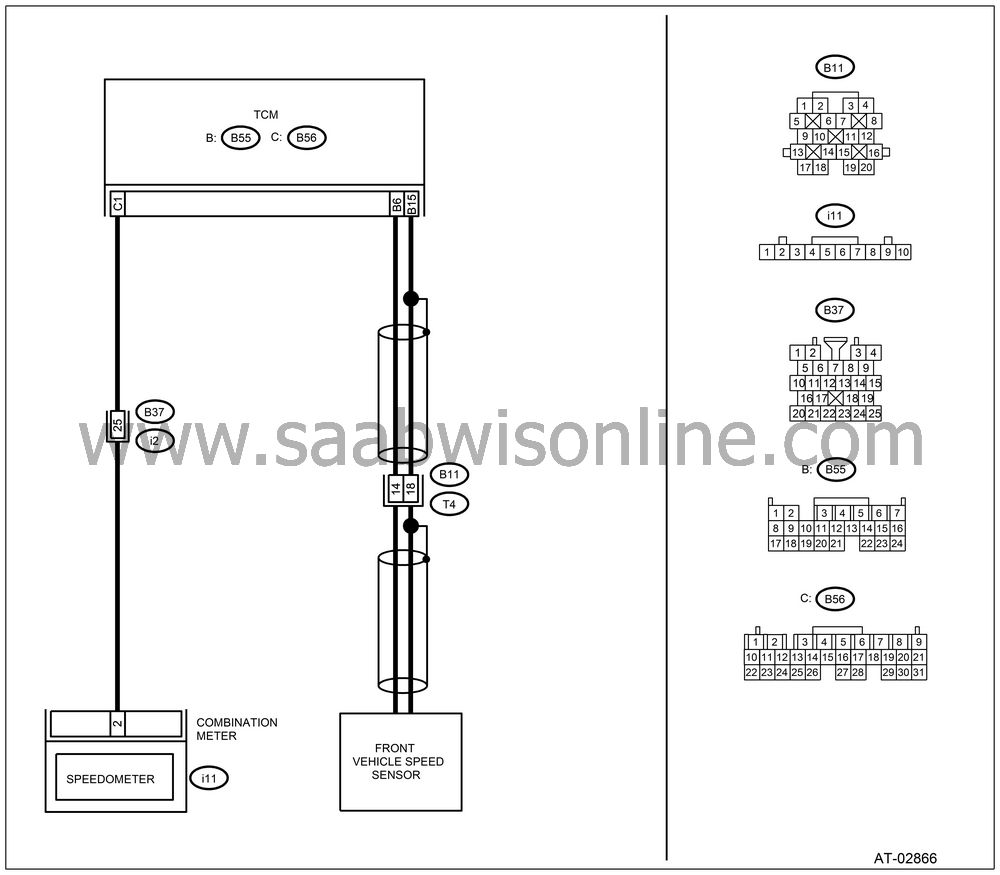
WIRING DIAGRAM:

CHECK HARNESS CONNECTOR BETWEEN TCM AND TRANSMISSION.
Turn the ignition switch to OFF.Disconnect the connector from TCM and transmission.
Measure the resistance of harness between TCM and transmission connector.
Connector & terminal
(B55) No. 6 — (B11) No. 14:
Is the resistance less than 1 Ω?
| Yes |
| No |
Repair the open circuit in harness between TCM and transmission connector.
CHECK HARNESS CONNECTOR BETWEEN TCM AND TRANSMISSION.
Measure the resistance of harness between TCM and transmission connector.Connector & terminal
(B55) No. 15 — (B11) No. 18:
Is the resistance less than 1 Ω?
| Yes |
| No |
Repair the open circuit in harness between TCM and transmission connector, and poor contact in coupling connector.
CHECK HARNESS CONNECTOR BETWEEN TCM AND TRANSMISSION.
Measure the resistance of harness between TCM and transmission connector.Connector & terminal
(B55) No. 6 — Chassis ground:
Is the resistance more than 1 MΩ?
| Yes |
| No |
Repair the short circuit in harness between TCM and transmission connector.
CHECK HARNESS CONNECTOR BETWEEN TCM AND TRANSMISSION.
Measure the resistance of harness between TCM and transmission connector.Connector & terminal
(B55) No. 15 — Chassis ground:
Is the resistance more than 1 MΩ?
| Yes |
| No |
Repair the short circuit in harness between TCM and transmission connector, and poor contact in coupling connector.
CHECK FRONT VEHICLE SPEED SENSOR.
Measure the resistance between transmission connector receptacle’s terminals.Connector & terminal
(T4) No. 14 — No. 18:
Is the resistance 450 — 650 Ω?
| Yes |
| No |
Replace the front vehicle speed
sensor.

CHECK INPUT SIGNAL FOR TCM USING Vehicle Diagnostic Interface.
Connect all connectors.Connect the Vehicle Diagnostic Interface to data link connector.
Lift-up the vehicle and place rigid racks.
| Note | ||
|
Raise all wheels off floor. |
Turn the ignition switch to ON and turn Vehicle Diagnostic Interface switch to ON.
Start the engine.
Read the data of vehicle speed using Vehicle Diagnostic Interface.
| • |
Compare
the speedometer reading with Vehicle
Diagnostic Interface indications.
|
|
| • |
Vehicle speed is indicated in “km/h” or “MPH”.
|
|
Slowly increase the vehicle speed to 60 km/h or 37 MPH.
Does the speedometer indication increase as Vehicle Diagnostic Interface front speed sensor data increases?
| Yes |
Even if the POWER indicator blinks, the circuit has returned to a normal condition at this time. A temporary poor connector or harness may be the cause. Repair the harness or connector in front vehicle speed sensor circuit.
| No |
CHECK POOR CONTACT.
Is there poor contact in front vehicle speed sensor circuit?
| Yes |
Repair the poor contact.
| No |


