PRE-RELEASE
INSTALLATION
| INSTALLATION |
|
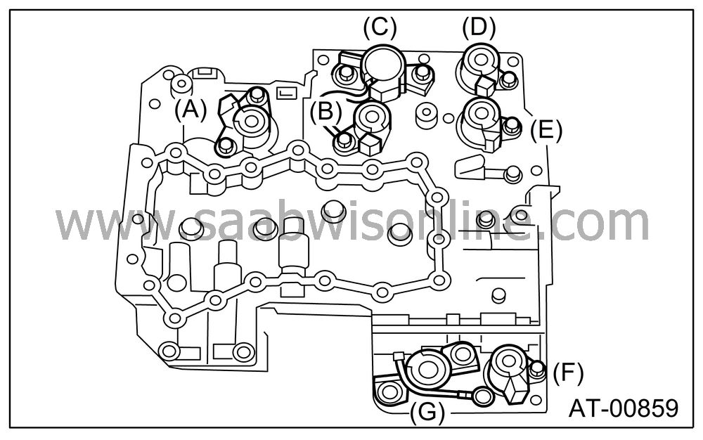
(A)
|
Lock-up
duty solenoid (Blue)
|
|
(B)
|
Low clutch
timing solenoid (Gray)
|
|
(C)
|
Line pressure
duty solenoid (Red)
|
|
(D)
|
Shift solenoid 2
(Yellow)
|
|
(E)
|
Shift solenoid 1
(Green)
|
|
(F)
|
2-4 brake
timing solenoid (Black)
|
|
(G)
|
2-4 brake
duty solenoid (Red)
|
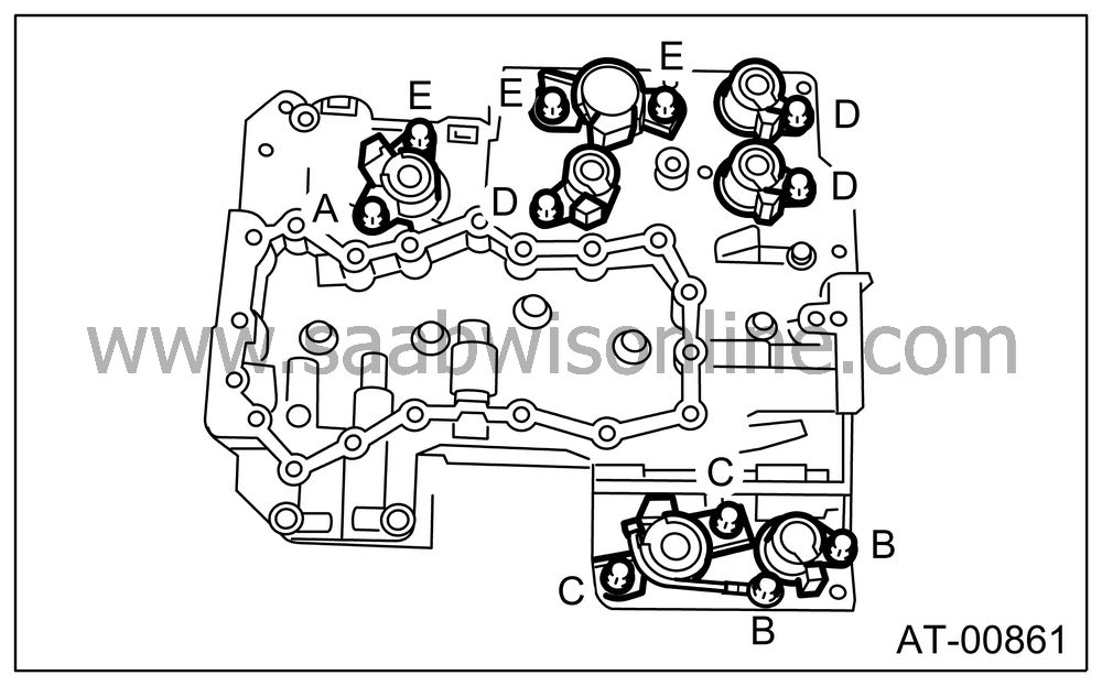
Tighten the bolts and nuts.
Tightening torque:
8 Nm (0.8 kgf-m, 5.8 ft-lb)
|
Bolt length
mm (in)
|
|
|
(A)
|
12 (0.47)
|
|
(B)
|
40 (1.57)
|
|
(C)
|
45 (1.77)
|
|
(D)
|
62 (2.44)
|
|
(E)
|
73 (2.87)
|
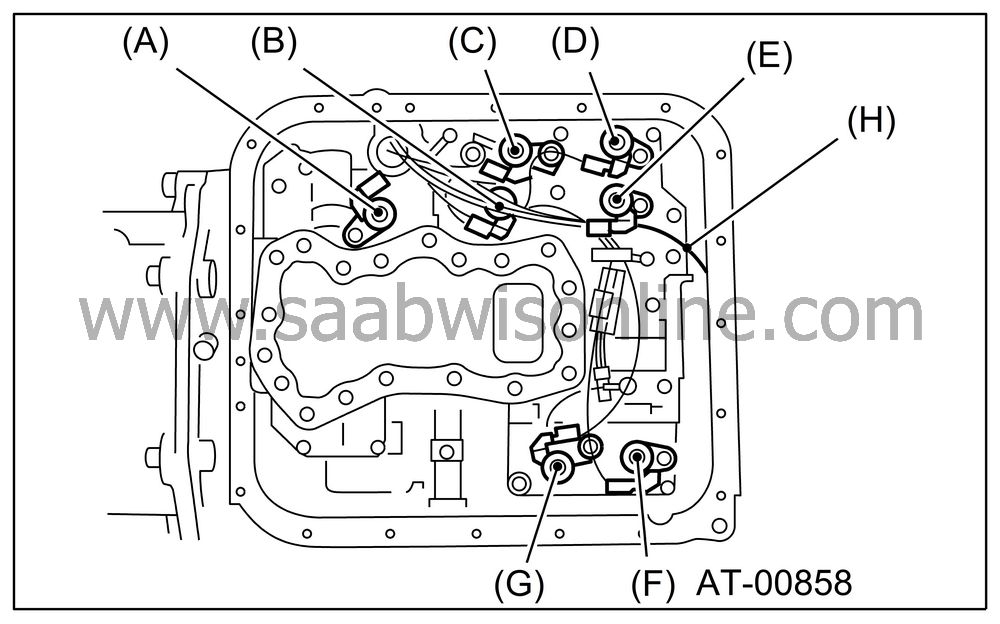
Connect the harness connectors.
Connect the connectors of same color, and secure the harness to valve body using clips.
|
(A)
|
Lock-up
duty solenoid (Blue)
|
|
(B)
|
Low clutch
timing solenoid (Gray)
|
|
(C)
|
Line pressure
duty solenoid (Red)
|
|
(D)
|
Shift solenoid 2
(Yellow)
|
|
(E)
|
Shift solenoid 1
(Green)
|
|
(F)
|
2-4 brake
timing solenoid (Black)
|
|
(G)
|
2-4 brake
duty solenoid (Red)
|
|
(H)
|
Transfer
duty solenoid (Brown)
|
Apply proper amount of liquid gasket to the entire oil pan mating surface.
Fluid packing:
THREE BOND 1217B (Part No. 32005004)
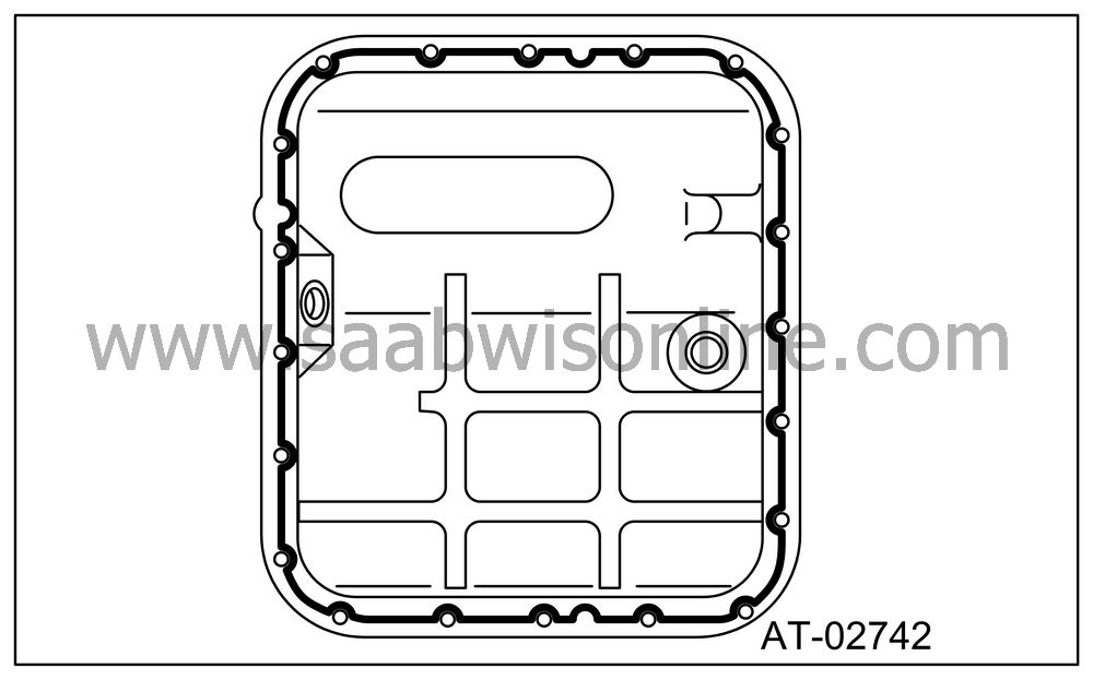
Apply liquid gasket fully to three holes other than screw holes on transmission case.
Fluid packing:
THREE BOND 1217B (Part No. 32005004)
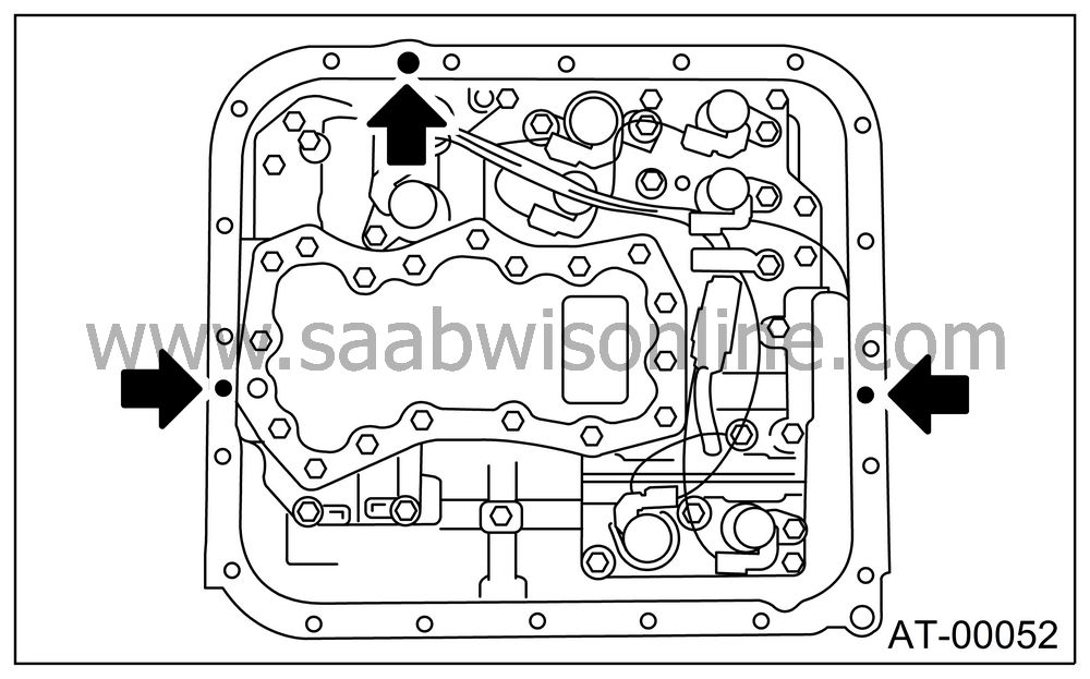
Install the oil pan.
Tightening torque:
5 Nm (0.5 kgf-m, 3.6 ft-lb)
Fill ATF up to the middle of the “COLD” side on level gauge by using the gauge hole.

Check the ATF level.

| ATF TEMPERATURE SENSOR |
For installation of ATF temperature sensor, refer to “Front Vehicle Speed Sensor.”


