PRE-RELEASE
TCS/ESP, detailed description
| TCS/ESP, detailed description |
The ABS function (Anti Block System) allows the solenoid valves (inlet/outlet valves) and the pump the regulate the hydraulic brake pressure when retardation of one wheel is greater than that of the other wheels. The hydraulic brake pressure can be kept constant or can be reduced in order for each wheel to employ maximum brake power for the road surface.
EBD (Electronic Brake-force Distribution) allows the control module to regulate brake force distribution between the front and rear wheels with help from solenoid valves (inlet/outlet valves). The pump is not active during EBD modulation.
TCS (Traction Control System) function allows the control module to make maximum use of friction for the driving wheels during acceleration. A limited wheelspin can be adjusted with brake application and a request to the ECM for engine torque limitation. The control module activates the pressure increase valve, pressure relief valve and the pump in order to create and adjust pressure to the drive wheel for which the brake is applied when wheel spin exceeds the accepted limit.
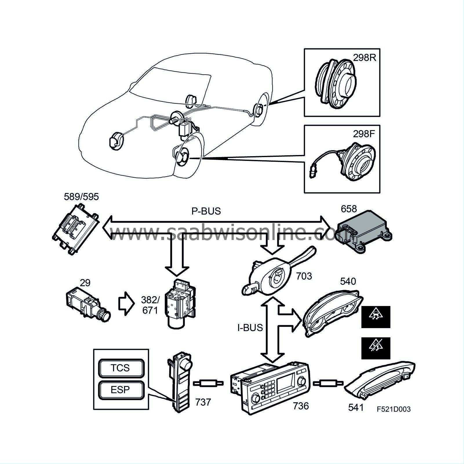
When the ignition key is turned to the ON position, the control module is activated, the ABS lamp and TCS OFF/ESP ON symbols in the MIU with a fixed glow during function check. The lamps extinguish after 3-5 seconds if no faults are found.
| Wheel-speed signal output |
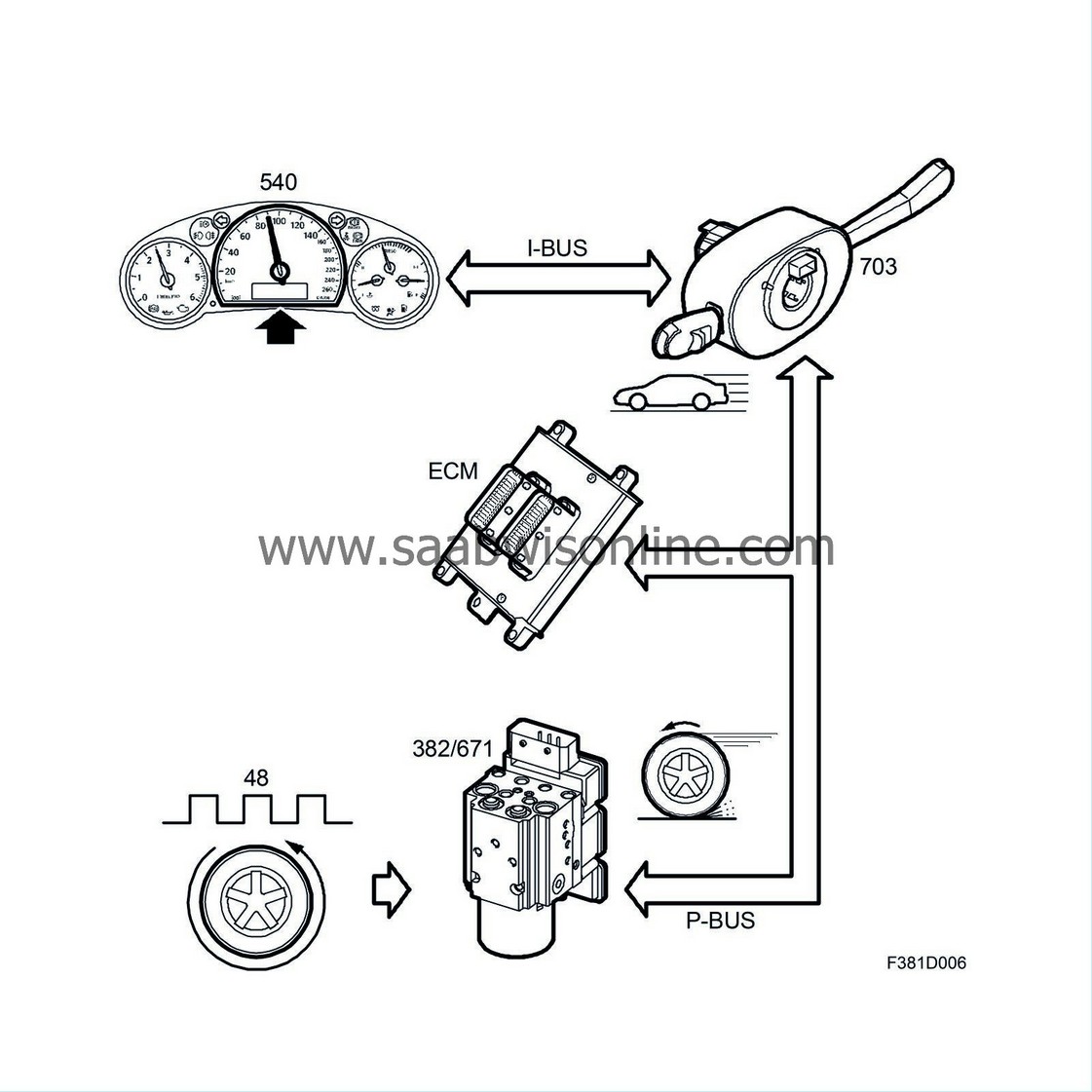
Several other car systems require information regarding vehicle speed. The control module, which is connected to the P-bus, provides information regarding the speed of all wheels.
Wheel speed information is converted in the ECM to information regarding vehicle speed in km/h (mph). The engine control module for petrol engines uses the rear left wheel with the rear right as a reserve if there is a fault in the rear left wheel sensor. The engine control module for diesel engine uses the left front wheel with the right front wheel as a reserve.
Speed is adjusted depending on tyre size and vehicle speed information is sent out on the P-bus.
The CIM unit converts vehicle speed to the I-bus and sends it to other control modules.
There is an output on pin 18 which can be used by other systems, which cannot process bus information, to access wheel speed information.
Speed information can be sent even if the ABS, footbrake, TCS OFF or ESP OFF warning lamps are lit. The information is send as long as one of the rear wheel sensors is functional, the control module is operating and receives a power supply.
For more information regarding wheel speed on the bus, see Function description, bus communication .
| Pump function |
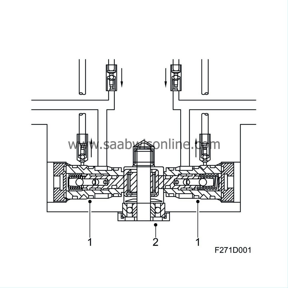
1 Pump housing
2 Pump motor eccentric shaft
The pump is integrated in the hydraulic unit and consists of two pump elements and a DC motor. Each pump element is driven by a motor which has an eccentric wheel in one shaft end.
The pump has two control valves (inlet and outlet valves) and receives brake fluid from the accumulator chamber (LPA).
The hydraulic pump and electric motor are an integral part of the valve block and cannot be replaced separately.
Compression stroke
The pump is filled via the inlet duct, the motor starts and the pistons starts brake fluid evacuation.When the pressure build-up has reached the level required to close the pump inlet valve, the pump continues to build pressure until the outlet valve opens.
Return stroke
The pistons retract with their return springs. When the pressure is reduced at the pump outlet valve, the valve closes due to the reduced volume and the pressure difference over the ball in the pump outlet valve.When the pump outlet valve is closed, the pump is filled with more brake fluid from the accumulator chamber.
ABS mode
The pump unit, which is only activated when an outlet valve is open, returns surplus brake fluid to the master cylinder.The pressure in the returned brake fluid is determined by the brake pressure in the master cylinder, which is in turn proportional to the pedal pressure applied.
TCS and ESP mode
The pump is continuously active during ESP and TSP modulation with braking.Pressure is built up by closing the pressure relief valve and opening the pressure increase valve to supply the pump with brake fluid. The control module closes the pressure increase valve when a pre-set pressure is reached.
The pressure is then modulated as the control module opens the pressure increase valve to boost the pressure, keeps the pressure increase and pressure relief valves closed (to maintain pressure) and opens the pressure relief valve to reduce the pressure. The excess brake fluid resulting from opening the pressure relief valve is returned to the master cylinder.
| EBD (Electronic Brake-force Distribution) |
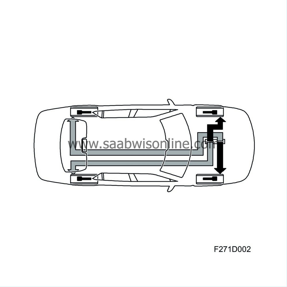
EBD, which is integrated with the control module, is a function which can be compared to a load sensing valve for the rear wheel brakes. For optimum braking and steering stability, the maximum braking force must be applied to both the front and rear wheels for all conditions/loads. The control module prevents the rear wheels from receiving excessive braking force by regulating brake pressure.
EBD modulation occurs sooner than the normal ABS mode and provides the occupants of the car with a more comfortable ride. The pump is not used during EBD modulation.
During braking, it is important for proper steering stability that the rear wheels do not lock first. In order to achieve this under different load conditions (e.g. a heavily loaded car requiring greater braking force in order to lock the wheels), the control module uses wheel speed to modulate the braking force on the rear wheels with help from the inlet solenoid valves. This prevents excessive permissible slip between the front and rear wheels.
When the criteria are met, the rear wheel inlet valves close and the EBD function is activated in order to regulate slip between front/rear wheels and provide stability. If any of the wheels locks during EBD modulation, the control module switches to normal ABS modulation.
| CBC (Cornering Brake Control) |
CBC is a function that is used when the brakes show a tendency to lock. The function operates in combination with EBD and ABS in order to stabilise vehicle lateral and yaw rate movements in situations when the driver corners while braking. Modulation takes place by braking the four wheels individually.
CBC determines if the vehicle is cornering and approaching oversteer by comparing the four wheel speeds. If the vehicle shows a tendency towards oversteer at the same time as the driver depresses the brake pedal, CBC will begin adjustment.
The function is included in TCS and ESP and is activated before ABS modulation. This means that the function only operates with the brake pressure applied by the driver and regulates brake pressure with help from the inlet and outlet valves. The system limits rear braking force and primarily adjusts the front wheel brakes in order to achieve stability.
CBC includes functions which prevent activation on roads with uneven surfaces.
CBC requires information regarding
| - |
wheel speed from all four wheels
|
|
| - |
driver braking
|
|
CBC uses
| - |
The four inlet and outlet valves in order to adjust brake pressure.
|
|
CBC is activated in extreme situations only and prevents the car from oversteering.
| ABS function |
The ABS system provides optimum braking without any loss of directional stability.
Braking force/Tyre slip
The diagram shows braking force as a function of tyre slip.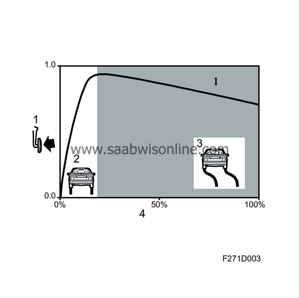
1 Braking force
2 Stable position
3 Unstable position
4 Tyre slip
The braking force is equivalent to the coefficient of adhesion or the friction between the tyre and the road surface. Each application of braking force gives rise to a certain degree of slip. The slip of a freely rotating wheel is expressed as 0% and of a locked wheel as 100%.
When the brake is first applied at 0% slip, braking force increases sharply but the degree of slip increases only gradually up to a certain limit. Beyond that point, braking force decreases with increasing slip.
Lateral force/Tyre slip
The diagram shows lateral force as a function of tyre slip.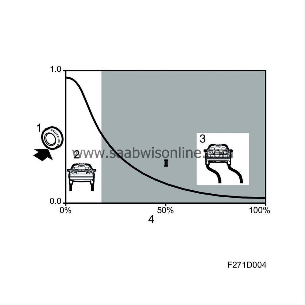
1 Lateral force
2 Stable position
3 Unstable position
4 Tyre slip
The maximum braking force is reached at a point known as the limit of optimum slip. The section of the curve between 0% slip and the limit of optimum slip is called the stable braking zone, and the section of curve between the limit of optimum slip and 100% slip is called the unstable braking zone, as stable braking cannot be achieved within this zone. This is because the wheel quickly becomes locked after the limit of optimum slip has been reached, unless the braking force is immediately reduced.
Slip also occurs when the tyre is called upon to transmit a lateral force, e.g. during cornering. Diagram 2 shows how the lateral force falls away sharply with increasing slip. At 100% slip, i.e. when the wheels have locked up, no lateral force remains for steering and the driver will no longer be able to control the vehicle.
The diagram shows both curves with ABS modulation range above.
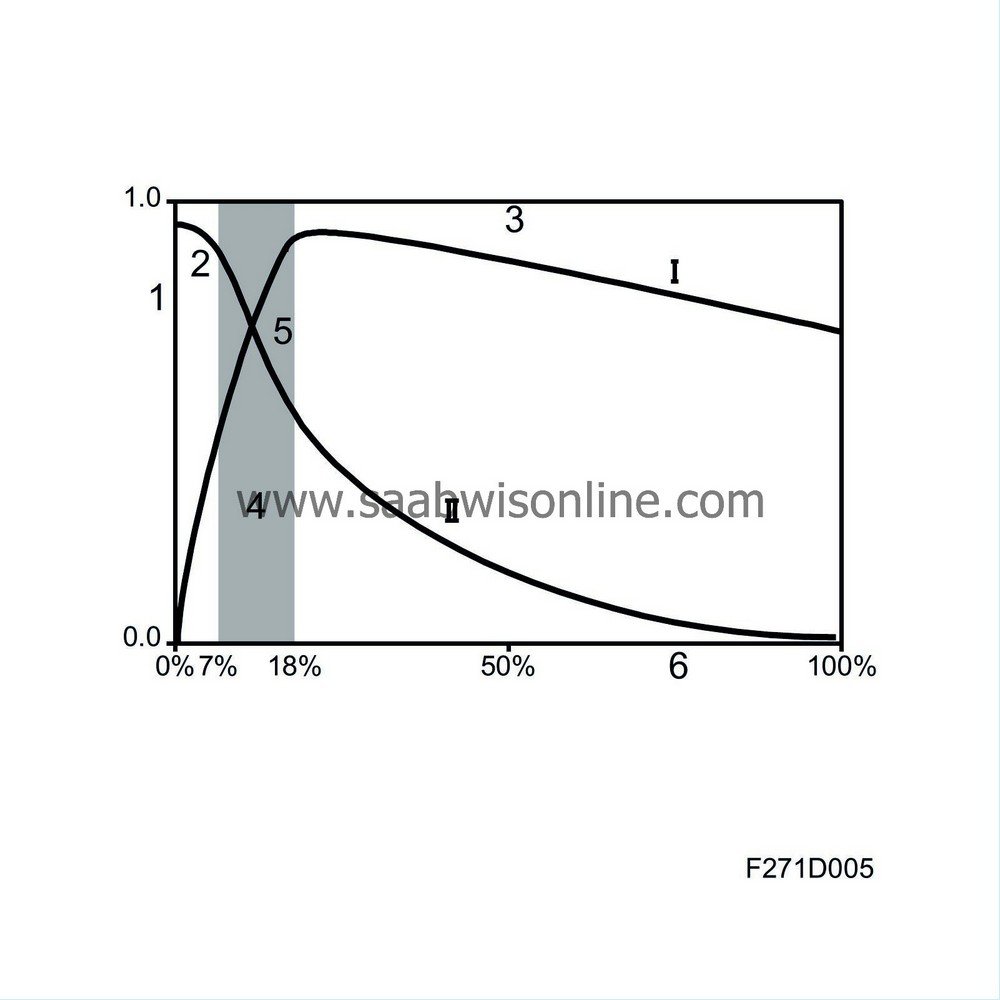
1. Braking/lateral force
2. Stable position
3. Unstable position
4. ABS operating range
5. Limit of optimum slip
6. Tyre slip
During braking, the braking force is allowed to increase to a point near the limit of optimum slip when ABS prevents further braking force. Hydraulic pressure is then adjusted so that the braking force is kept as close to the optimum level (limit of optimum slip) as possible, irrespective of how hard the driver depresses the brake pedal.
Thus, because the ABS system prevents the degree of slip from exceeding the limit of optimum slip, the car never enters the unstable braking zone. At the same time, some lateral force is preserved to ensure that steering control can be maintained (curve II).
ABS modulation
The diagram shows ABS modulation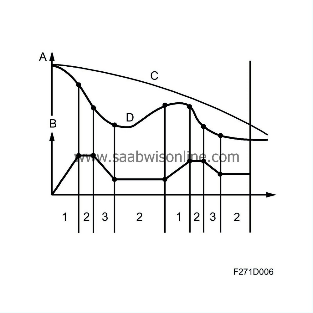
A Speed
B Braking force
C Road speed
D Wheel rotation speed
1 Modulation phase 1; inlet valve open, outlet valve closed
2 Modulation phase 2; Inlet valve closed, outlet valve open
3 Modulation phase 3; Outlet valve closed, pump activated
When the control unit detects excessive retardation (speed decrease) for one of the wheels, it modulates the brake pressure to the wheel in three phases:
| - |
PHASE 1 Pressure increase
|
|
| - |
PHASE 2 Pressure holding
|
|
| - |
PHASE 3 Pressure decrease
|
|
PHASE 1 Pressure increase
Inlet valve is open, outlet valve is closed and the pressure is allowed to build.Wheel rotation speed is reduced.
PHASE 2 Pressure holding
Inlet valve closes, outlet valve is closed. This prevents an increase in brake pressure to the caliper and provides a flow of brake fluid upstream of the inlet valve for use in phase 1.Wheel rotation speed is allowed to increase.
PHASE 3 Pressure decrease
The outlet valve opens and at the same time opens the passage from the caliper to the hydraulic accumulator which quickly receives the pressure from the caliper. At the instant the outlet valve opens, the control module starts the pump, which pumps the fluid back to the master cylinder. The wheel rotation speed will now increase.When the outlet valve closes, the pump stops running and the inlet valve opens. This results in a reduction of wheel rotation speed.
PHASES 1-3
These phases are repeated until either the brake is released or sufficient adhesion (friction) returns between the tyre and the road surface. In the event of a circuit break or a short circuit, the valves will return to their rest position and conventional braking without ABS modulation is obtained| TCS function |
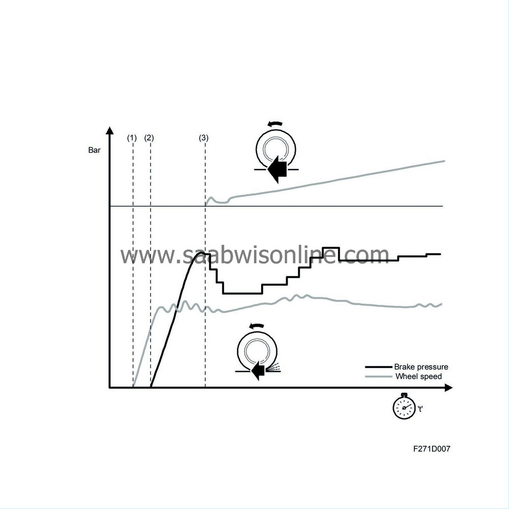
The TCS function in the control module employs both reduction of engine torque (request to engine control module) brake application on the driving wheels in order to utilise the friction of the road surface in all driving conditions.
To understand the TCS function it is best to assume that the road surface is slippery, with varying degrees of friction under the two drive wheels.
The rotational speed of the rear wheels is used as a reference for comparing the speed of the drive wheels individually. Wheelspin is described as the result of when either of the drive wheels rotates at a higher speed than the rear wheels. The magnitude of this wheelspin and the speed of the car are decisive with regards to system functionality.
At low speeds, traction is given priority and the system operates primarily by braking. The purpose of this is to provide a certain amount of braking torque to the drive wheel having the lowest friction (the wheel that spins first).
This allows more power to be transferred to the other drive wheel, which then has maximum traction. Through this distribution of the power applied to the wheels, the available friction can be utilised to maximum effect.
Wheelbrakes provide a quick and forceful way to retard spinning wheels while engine torque limitation is the gentler, more comfortable way. These processes often operate simultaneously and certain driving cases demand braking, for example starting on an incline with different friction on both drive wheels. Braking is applied to the wheel with the least friction to such a degree that the traction is transferred to the other drive wheel, which achieves better traction due to the differential brake.
A certain degree of wheelspin is always allowed so that the sporty feel and handling of the car will still be retained. This varies with the speed of the car, the friction between the tyres and the road surface and how "aggressively" the car is being driven (position of the accelerator pedal).
If the driver brakes during TCS modulation, the TCS function with brake application will be switched off and braking function will be selected. The control module will continue TCS modulation using engine torque limitation.
Low speed
When starting on a slippery surface, the following will happen:The drive wheel having the lowest friction begins to spin first. When wheelspin is detected by the control module through the wheel sensors, TCS modulation starts by applying the brakes.
When the wheel is braked, additional tractive power is transferred to the other wheel which still has a grip on the road. If the road surface does not have much friction, the other wheel may begin to spin. When wheelspin occurs, the control module will send an engine torque limitation request to the ECM which then prevents further wheelspin.
The optimum combination of tractive power and steering ability is thus achieved as well as the same traction as with the use of a differential brake.
A relatively high degree of wheelspin is accepted when starting in order to retain the feeling of sportiness and also enable the wheels to dig themselves down to a firmer surface whenever conditions make this necessary.
High speed
At speeds higher than 40 km/h (25 mph), the TCS function changes its mode of operation and starts modulation with engine torque limitation of the wheel that first starts to spin, i.e. the wheel with the lowest friction.Modulation with brake application is used to brake the spinning wheel when engine torque limitation is inadequate.
Braking is used at speeds up to 40 km/h (25 mph).
Primary limitation of engine torque means that no extra tractive force is transferred to the outer wheel when cornering. The outer wheel then has a sufficient margin of grip to take up steering forces to the full. The driver avoids being taken by surprise as the front wheels suddenly lose traction.
TCS modulation
Since TCS modulation braking occurs without depression of the brake pedal, the hydraulic unit must build up and modulate the pressure to the driven wheel which is to be braked if it develops wheelspin in excess of the permitted limit.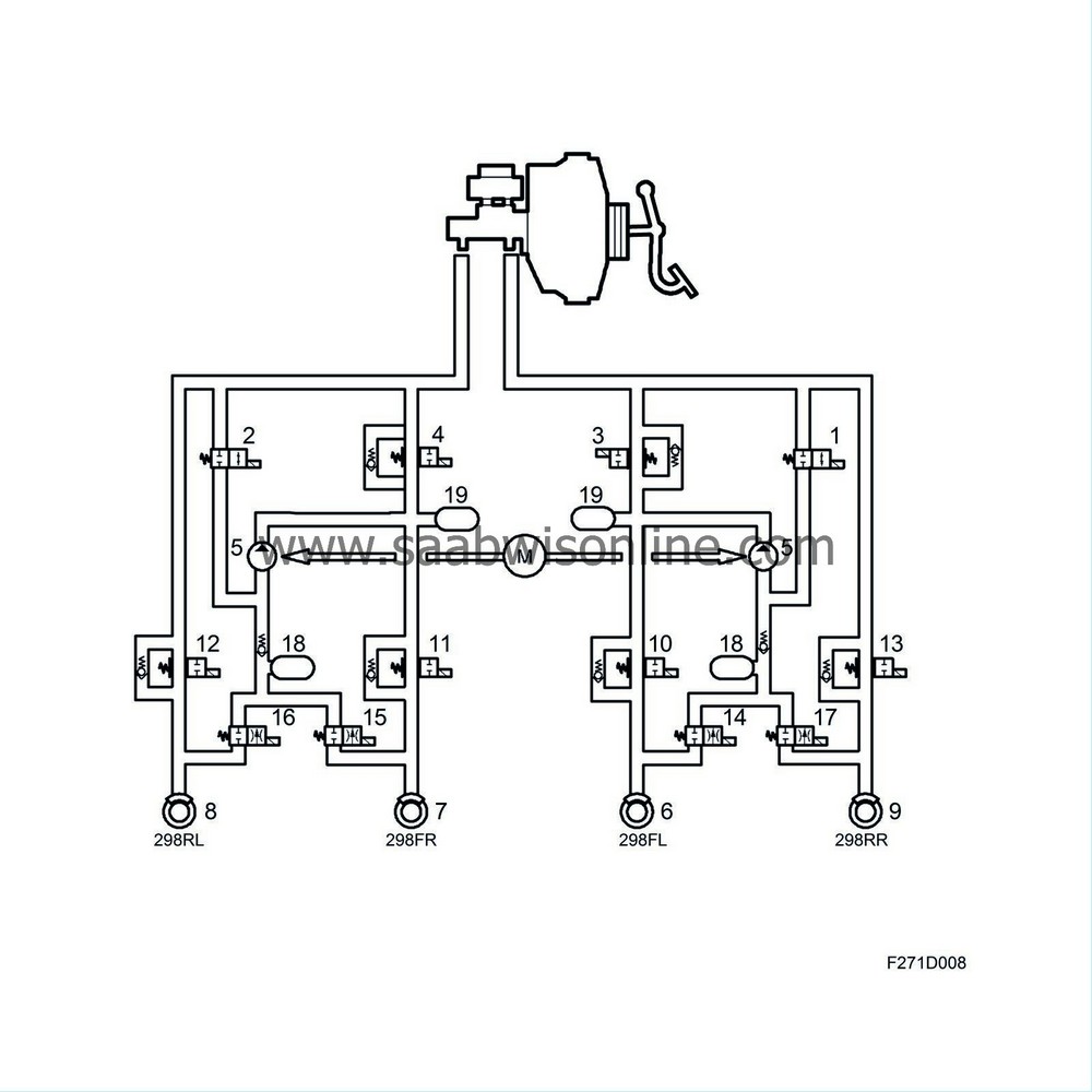
1 Pressure Increase Valve Front Left
2 Pressure Increase Valve
3 Pressure Relief Valve Left Front
4 Pressure Relief Valve Front Right
5 Pump
6 Wheel sensor, FL
7 Wheel sensor, FR
8 Wheel sensor, RL
9 Wheel sensor, RR
10 Inlet valve, FL (ABS)
11 Inlet valve, FR (ABS)
12 Inlet valve, RL (ABS)
13 Inlet valve, RR (ABS)
14 Outlet valve, FL (ABS)
15 Outlet valve, FR (ABS)
16 Outlet valve, RL (ABS)
17 Outlet valve, RR (ABS)
18 Accumulator chamber
19 Pressure chamber
The control module performs TCS modulation with braking when the following criteria are met
| - |
The driver does not depress the brake pedal, the brake light switch input is not active.
|
|
| - |
Road speed is below 40 km/h.
|
|
| - |
One of the driven wheels is spinning more than the permissible limit.
|
|
When TCS modulation with braking occurs, the vacuum servo, primary piston and secondary piston are in their rest positions. In the valve block the inlet and outlet valves are in their rest positions, that is to say the inlet valves are open and the outlet valves are closed.
The control module starts the pump while the pressure relief valve is closed in order to allow pressure build-up to occur. Pressure is built up by opening the pressure increase valve in order to supply the return pump with brake fluid. The control module closes the pressure increase valve when the pre-determined pressure has been reached. The pressure is then modulated as the control module opens the pressure increase valve to increase pressure, keeps both the pressure increase and pressure relief valves closed to retain pressure and opens the pressure relief valve to reduce pressure. The excess brake fluid resulting from opening the pressure relief valve is returned to the master cylinder.
When TCS modulation starts, a "filling pulse" is generated, which means that a small amount of pressure (same for both wheels) is built up in the wheel cylinders for both driven wheels irrespective of the wheel for which modulation with braking will occur.
Pressure will be maintained on the front wheel for which braking will not occur, i.e. both the pressure increase and pressure relief valves will be closed. This is in order to prepare for an application of the brakes if necessary.
The pressure increase valve on the wheel which is spinning will open. This causes an increase in the pressure to the wheel cylinder and the wheel is braked.
Modulation continues until:
| - |
The friction between wheels and road surface changes so that wheelspin does not exceed the limit.
|
|
| - |
The driver brakes (brake lights switch input active).
|
|
| - |
Modulation is interrupted due to the risk for overheating the brakes.
|
|
When modulation is interrupted, the control module stops the pump, closes the pressure increase valve and opens the pressure relief valve, i.e. the valves and the return pump resume their rest positions.
If TCS modulation is interrupted by the driver braking, TCS modulation with braking will be disengaged and the braking function will be chosen instead. Any delay that may then arise will not affect the braking function since the brake fluid can flow through the check valve which is mounted parallel with the pressure relief valve.
Interruption of TCS modulation with braking due to a risk for overheating the brakes occurs as a result of continuous recording of the aggregate duration of TCS modulation with braking over a certain period of time by the control module.
The time is compared with a pre-programmed maximum value and modulation with braking is disengaged when this is exceeded.
Braking phases
Phase 1 Pressure build-up on both front wheels (filling pulse and holding pressure) The driver does not brake.Filling pulse
When TCS modulation starts, a "filling pulse" is generated, which means that a small amount of pressure (same for both wheels) is built up in the wheel cylinders for both driven wheels irrespective of the wheel for which modulation with braking will occur. The pump starts, the pressure relief valve closes and the pressure increase valve opens (pre-determined amount of time).The inlet and outlet valves in the valve block are in their rest positions, i.e. the inlet valves are open and the outlet valves are closed.
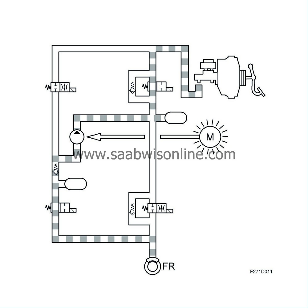
Holding pressure
When the filling pulse is concluded, the respective inlet valves close in order to prepare for individual modulation for each wheel.For wheels which will not be braked with TCS modulation: Pressure holding will occur by closing the pressure increase and pressure relief valves at each circuit and closing the inlet and outlet valves at each wheel. This is to prepare for possible application of the brakes.
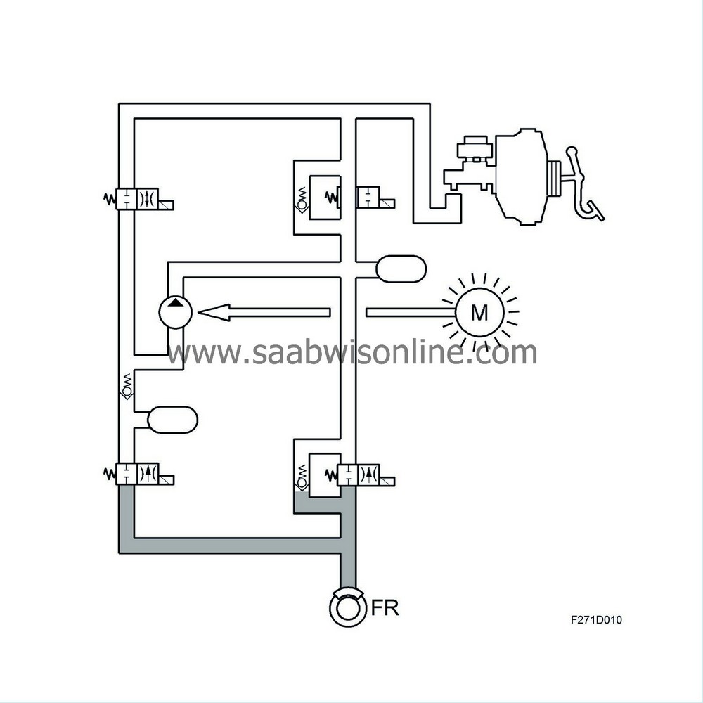
Phase 2 Pressure increase in the circuit with wheelspin
The pressure increase valve opens in order to supply the pump with brake fluid, which is pumped into the circuit, and the pressure relief valve is closed. The inlet valve for the wheel to be braked is opened until the conditions for pressure build-up have been met.This means that the pressure out to the wheel cylinder is also increased and the wheel is braked. The pump is running.
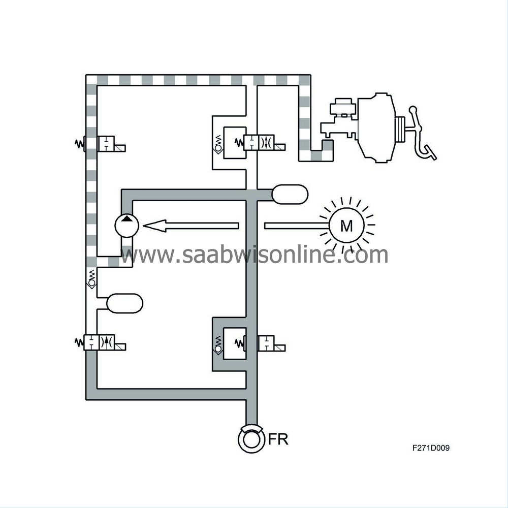
Phase 3 Pressure reduction in the circuit with wheelspin
The pressure increase valve is closed and the pressure relief valve is opened in order to relieve pressure in the circuit.The inlet valve is closed and the outlet valve is opened in order that the pressure out at the wheel is reduced.
Brake fluid is returned from the wheel outlet valve through the pressure relief valve out to the master cylinder. The pump is running.

Phase 4 Release
The criteria for TCS modulation have ceased. All valves resume their rest positions, i.e. the pressure relief valves are open, the pressure increase valves are closed, the inlet valves are open and the outlet valves are closed. The pump stops.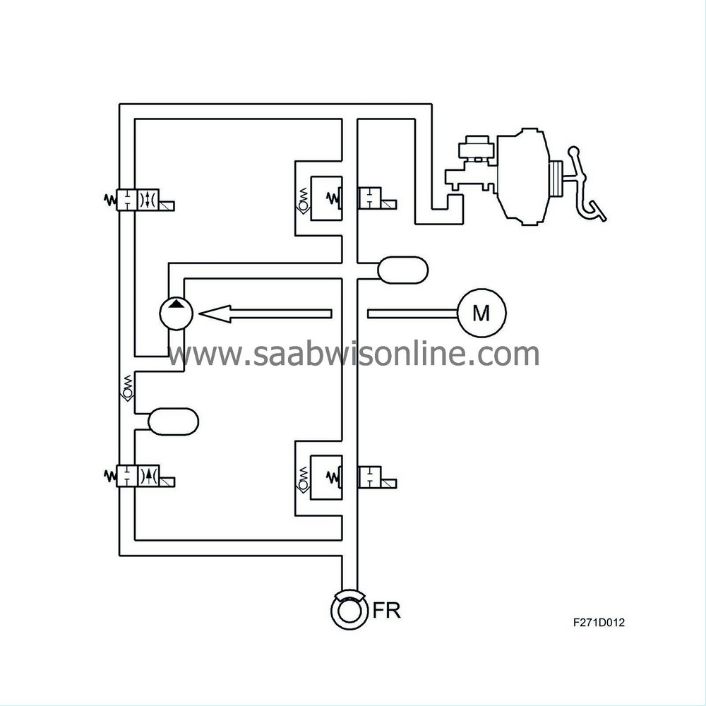
| ESP function |
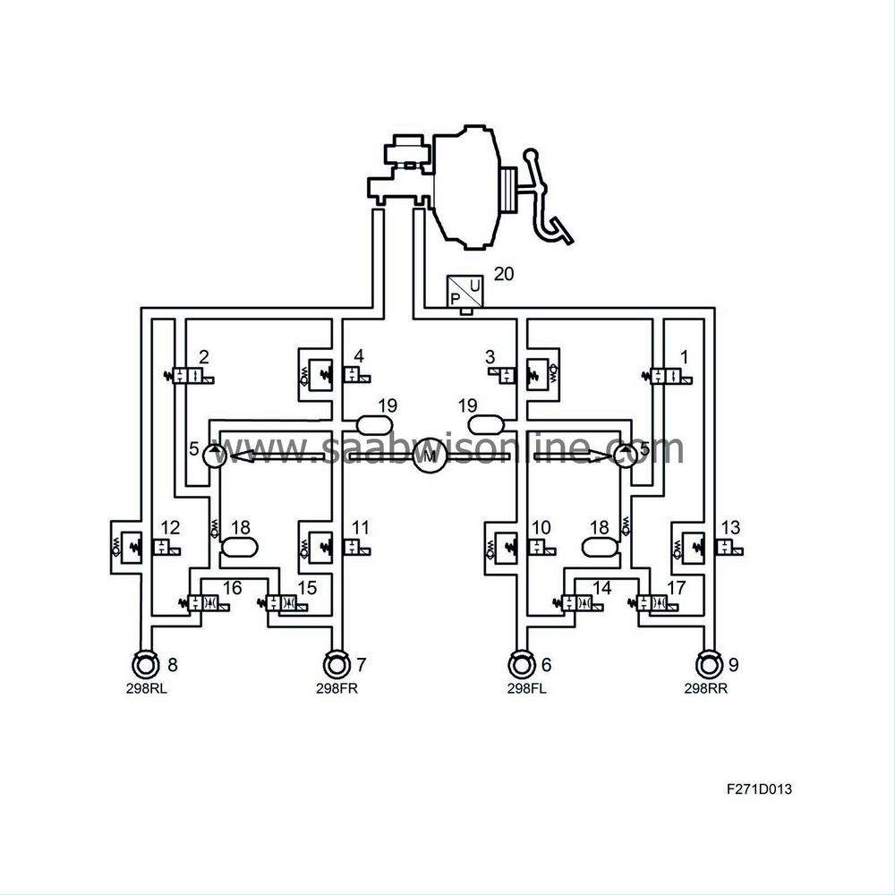
1 Pressure Increase Valve Front Left
2 Pressure Increase Valve
3 Pressure Relief Valve Left Front
4 Pressure Relief Valve Front Right
5 Pump
6 Wheel sensor, FL
7 Wheel sensor, FR
8 Wheel sensor, RL
9 Wheel sensor, RR
10 Inlet valve, FL (ABS)
11 Inlet valve, FR (ABS)
12 Inlet valve, RL (ABS)
13 Inlet valve, RR (ABS)
14 Outlet valve, FL (ABS)
15 Outlet valve, FR (ABS)
16 Outlet valve, RL (ABS)
17 Outlet valve, RR (ABS)
18 Accumulator chamber
19 Pressure chamber
20 Pressure sensors
On cars equipped with ESP
The Electronic Stability Program (ESP) helps to keep the vehicle on the right course when cornering, taking evasive action, braking and acceleration. The stabilising effect of the ESP system is based on calculations made by the control module which evaluates information received from the various system sensors.
| - |
Wheel speed sensors
|
|
| - |
Steering wheel angle sensor
|
|
| - |
Yaw rate sensor
|
|
| - |
Lateral acceleration sensor
|
|
| - |
Brake pressure sensor
|
|
Data from these sensors informs the control module of the driver's intentions, e.g. in which direction the driver intends to travel, if the driver is braking, etc.
The ESP control module, which is integrated in the hydraulic unit, continuously calculates the direction of the vehicle (actual value) and compares that value with the direction indicated by the steering wheel (desired value).
| • |
If the car starts to
understeer
(when the front tends to continue straight ahead in a bend), the yaw rate sensor measures a lower value than that calculated. The system applies the brakes on the inside rear wheel, followed by the outside rear wheel and the inside front wheel in the curve until the measured and calculated yaw rates (desired value) correspond.
|
|
| • |
If the car starts to
oversteer
(the rear tends to drift out), the measured yaw rate (actual value) will be greater than that calculated. The system will apply the brakes on the outside wheels until the measured and the calculated yaw rates (desired value) correspond.
|
|
When the system is activated, it can counteract a skid by braking one or two of the wheels without brake pedal application by the driver. The system reduces engine torque with an engine torque request to the engine control module and applies the brakes on all four wheels individually.
The ESP system comprises the ABS, TCS and ESP functions. The ABS and TCS functions retain the same functions as earlier, see the corresponding description of operation.
Engine torque regulation
Engine torque regulation takes place after bus communication with the engine control module during which the ESP control module requests a specific engine torque from the engine management system. Engine torque is then regulated with ignition retardation and throttle control, i.e. changing the throttle angle and boost pressure (air mass/combustion). By using engine torque regulation, the brakes need not be applied as often, resulting in a higher degree of comfort.This action means that kinetic energy in the drive wheels is converted to heat in both cases. Applying the brakes heats the wheel brakes and ignition retardation raises the exhaust temperature. In order to protect the turbocharger and catalytic converter, ignition retardation does not occur at high exhaust temperatures.
Braking
The brakes are applied through ESP control of the pump motor, pressure increase and pressure relief valves, as well as the inlet and outlet valves in the hydraulic unit. This allows the braking force for each wheel to be controlled individually. The ESP control module receives information from the brake pressure sensor and uses this information to control brake pressure on each wheel in relation to the braking force applied by the driver. A wheel regulated by ESP in controlled using the ESP criteria.Both front and rear wheels are connected to the pressure increase and pressure relief valves in the hydraulic unit, which allows each wheel to be controlled independently.
Friction is estimated by calculating drive wheel torque during acceleration (which is a function of the engine torque) or braking (which is a function of braking force).
If performing evasive action during emergency braking, the vehicle can be manoeuvred by regulating the braking pressure applied by the driver using the control module and pump. The applied braking force on each wheel can therefore be above or below force requested by the driver.
Braking distance is given priority when braking in a straight line while stability is given priority during evasive action. ESP modulation can occur with or without the driver applying the brake pedal.
Braking
During ESP modulation, the control module starts the pump which remains running during the entire modulation cycle. At the same time, the pressure relief valve is closed in order to allow pressure build-up. Pressure is built up through the opening of the pressure increase valve, which supplies the pump with brake fluid.The control module closes the pressure increase valve when a pre-set pressure is reached. The control module regulated pressure by opening of the pressure increase valve, closing the pressure increase and pressure relief valves to maintain pressure and opening the pressure relief valve in order to lower the pressure. The inlet and outlet valves are activated for individual wheel control.
The valves are activated with a pulse train, during which the time corresponds to a pressure increase or pressure decrease. Excess brake fluid remaining when the pressure relief valve opens is returned to the master cylinder.
The ESP function controls one to three wheels simultaneously.
Braking phases
Phase 1 Pressure build-up for all four wheels (filling pulse and maintaining pressure). Driver does not brake.Filling pulse
When TCS modulation starts, a "filling pulse" is generated, which means that a small amount of pressure (same for both wheels) is built up in the wheel cylinders for both driven wheels irrespective of the wheel for which modulation with braking will occur. The pump starts, the pressure relief valve closes and the pressure increase valve opens (pre-determined amount of time).The inlet and outlet valves in the valve block are in their rest positions, i.e. the inlet valves are open and the outlet valves are closed.

Holding pressure
When the filling pulse is concluded, the respective inlet valves close in order to prepare for individual modulation for each wheel.Wheels on which the ESP system does not apply brakes: Pressure will be maintained with the pressure increase and pressure relief valve closing on each circuit as well as closing of the inlet and outlet valves by each wheel. This occurs in order to prepare the system in the event that braking is necessary.

Phase 2 Pressure increase on wheels under ESP regulation
The pressure increase valve opens in order to supply the pump with brake fluid which is pumped into the circuit. The pressure relief valve is closed.The inlet valve for the wheel having its brakes applied will be opened until the conditions for pressure build-up have been met.
This means that the pressure out to the wheel cylinder is also increased and the wheel is braked. The pump is running.

Phase 3 Pressure reduction on wheels under ESP regulation
The pressure increase valve is closed and the pressure relief valve is opened in order to relieve pressure in the circuit.The inlet valve is closed and the outlet valve is opened in order that the pressure out at the wheel is reduced.
Brake fluid is returned from the wheel outlet valve through the pressure relief valve out to the master cylinder. The pump is running.

Driver braking
See Phases 1-3When the driver applies the brakes while ESP regulation is active, the brake pressure sensor informs the control module regarding input brake pressure in the hydraulic unit. With this information, brake pressure to the wheels not under ESP regulation can be controlled in correlation to the driver's braking force.
The wheel under ESP regulation when the brakes are applied is controlled according to ESP criteria.
Phase 4 Release
The criteria for ESP modulation have ceased. All valves resume their rest positions, i.e. the pressure relief valves are open, the pressure increase valves are closed, the inlet valves are open and the outlet valves are closed. The pump stops.
Modulation continues until:
| - |
vehicle movement is below the limit value for ESP regulation.
|
|
After regulation is terminated, the control module will stop the pump, close the pressure increase valve and open the pressure relief valve. The valves and the pump resume their resting positions.
Termination of regulation with brake application due to a risk for brake overheating is achieved by the control module, which continuously registers the total time that regulation with brake application has been active during a specific period of time.
The value is then compared to a programmed maximum value. If this value is exceeded, regulation with brake application is terminated.
| Wheel speed |
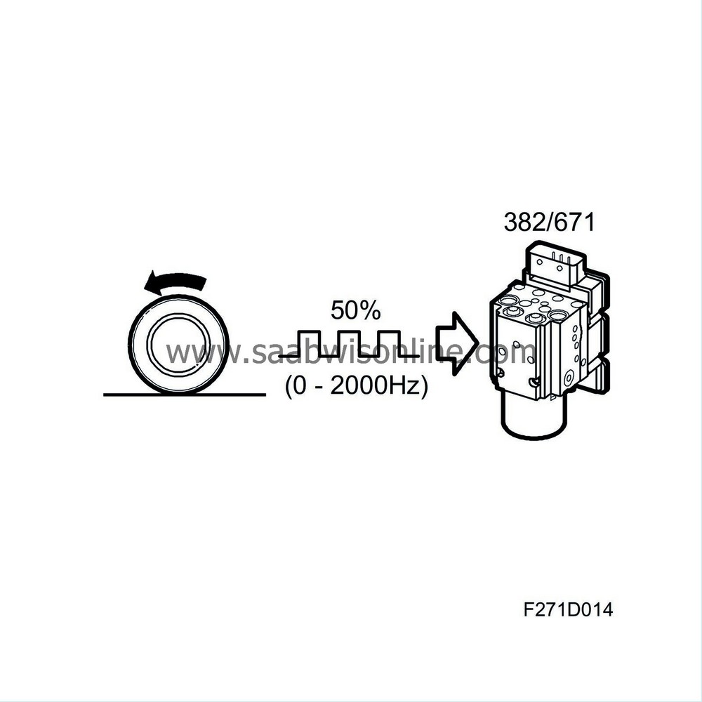
From the wheel sensors ( front / rear ), the control module receives information on the wheel speed. The control module uses this information on wheel speed to calculate the speed of the wheels in relation to each other.
If the difference in wheel speed exceeds the limit values, the control module acts accordingly by compensating with braking or an engine torque request.
| Steering wheel angle |
On cars equipped with ESP
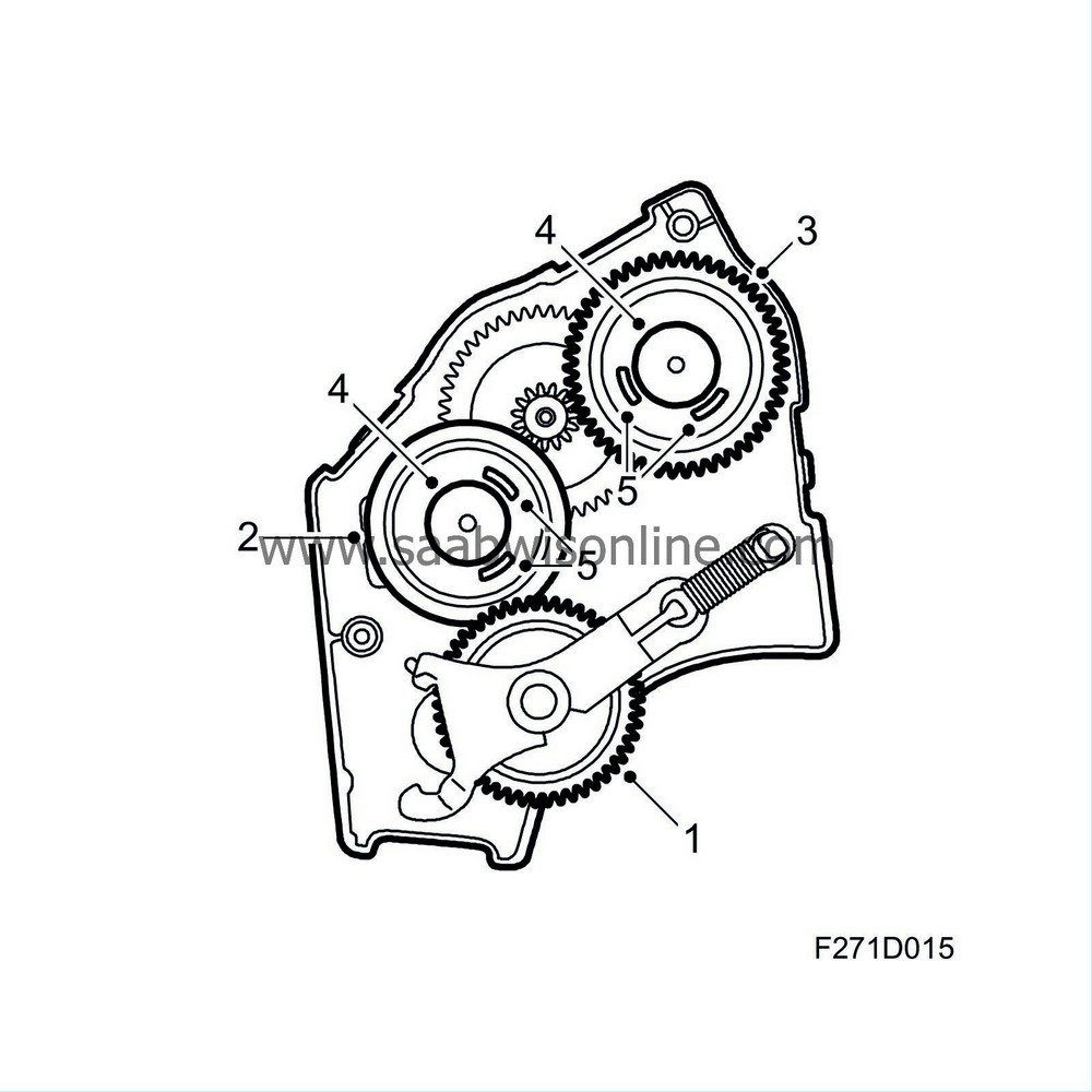
The steering wheel angle sensor is fully integrated in the CIM (Column Integration Module) that in turn is fitted in the steering column. The sensor sends information regarding the angle of the steering wheel, ±540°, or 2.9 steering wheel revolutions. 0° = straight ahead. When the steering wheel is rotated anticlockwise, it provides a positive (+) value.
The CIM sends this information on the P-bus and provides steering wheel angle sensor diagnostics. The ESP control module uses information on the driver's intentions, i.e. the direction in which the steering wheel is rotated, and calculates steering wheel rotation speed.
This information is sent to the ESP control module, which in turn calculates any regulation based on this desired value. The steering wheel angle sensor is connected with 4 pins in one circuit board in the CIM unit; pin for power supply (5V), grounding and communication with the main CIM unit processor.
The sensor comprises a main gear (1) which lies against the steering column and mechanically registers steering wheel movement. This main gear drives three additional gears.
Two of the gears are so-called measuring gears with different numbers of teeth which rotate at different speeds. As a result, their positions change at different times. One gear (2) has 45 teeth (nearest the main gear) and the other (3) has 49 teeth while both have an individual permanent magnet. Two Hall sensors are located by each magnet which register movement in the direction of the magnetic field. The sensors alter their resistance using the direction of the magnetic field registered by the sensors when the gears rotate.
The different rotation speeds of both measuring gears (2 and 3) are registered by electronics which calculate the steering wheel rotation position. The steering wheel angle sensor is calibrated for a 0 position. Using this measuring principle with two measuring gears which show absolute angle, the steering wheel angle sensor microprocessor can calculate the exact steering wheel angle.
When replacing the steering wheel angle sensor, it should be calibrated for a 0 position. This means that the wheels should be placed in a straight-ahead position since the steering wheel angle sensor is not equipped with a defined 0 position.
The CIM sends information regarding steering wheel position, when the steering wheel angle sensor has been calibrated and sensor status on the P-bus. The CIM diagnoses the Steering wheel angle sensor.
| Yaw rate |
On cars equipped with ESP
The yaw rate sensor measures rotation movement around the vehicle's centre of gravity. The purpose of the yaw rate sensor is to measure if the vehicle is rotating around its own vertical axis and register every instance of this movement, i.e. if the vehicle turns. The sensor sends this so-called actual value on the bus to the ESP unit control module which compares the value with the desired value from the steering wheel angle sensor.
Yaw refers to vehicle movement around its own axis, which is measured in degrees/sec. Yaw rate acceleration can also be calculated by measuring lateral acceleration, speed and steering wheel angle. If these three values correspond to the measured value from the yaw rate sensor (YRS), the system presumes that the vehicle is stable. The main components in the yaw rate sensor include a silicone ring gyro which uses frequencies to detect rotation movements.
See Technical description, Yaw rate sensor (658) and Technical data Yaw rate sensor (658) .
| Lateral acceleration |
On cars equipped with ESP
The lateral acceleration sensor registers lateral forces which arise during cornering. The sensor provides the control module with information regarding the intensity of the lateral forces which attempt to move the vehicle from its intended course. The sensor sends this so-called actual vale to the ESP unit control module, where the value is compared with the desired value from the steering wheel angle sensor.
Measuring of lateral acceleration occurs according to a capacitive principle.
A capacitor plate with a moving mass is suspended so that it can move freely. Two other fixed capacitor plates surround the moving capacitor, providing a structure using two series-coupled capacitors. With help from electrodes, the amount of capacitor charge storage capability can be measured. When the sensor is actuated by lateral acceleration, the condenser with the mass move towards the fixed capacitors, increasing the charge in the capacitor towards which the moving mass nears (measured in ampere).
See Technical description, Yaw rate sensor (658) and Technical data Yaw rate sensor (658) .
| Brake pressure |
On cars equipped with ESP
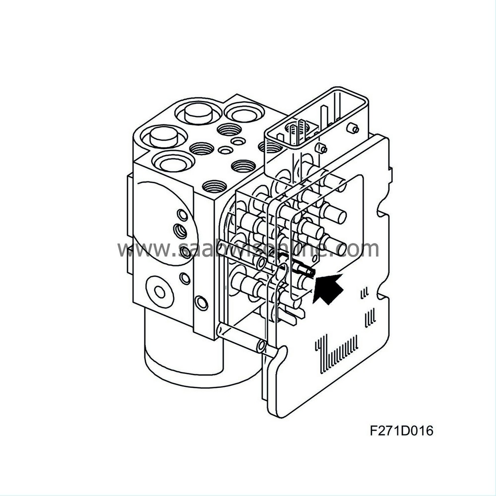
The brake pressure sensor is integrated in the ESP unit which measures input brake pressure from the master cylinder in the primary circuit (FL and RR) up to 350 bar.
The ESP control module uses information regarding current brake pressure in order to calculate correct braking force on the wheels.
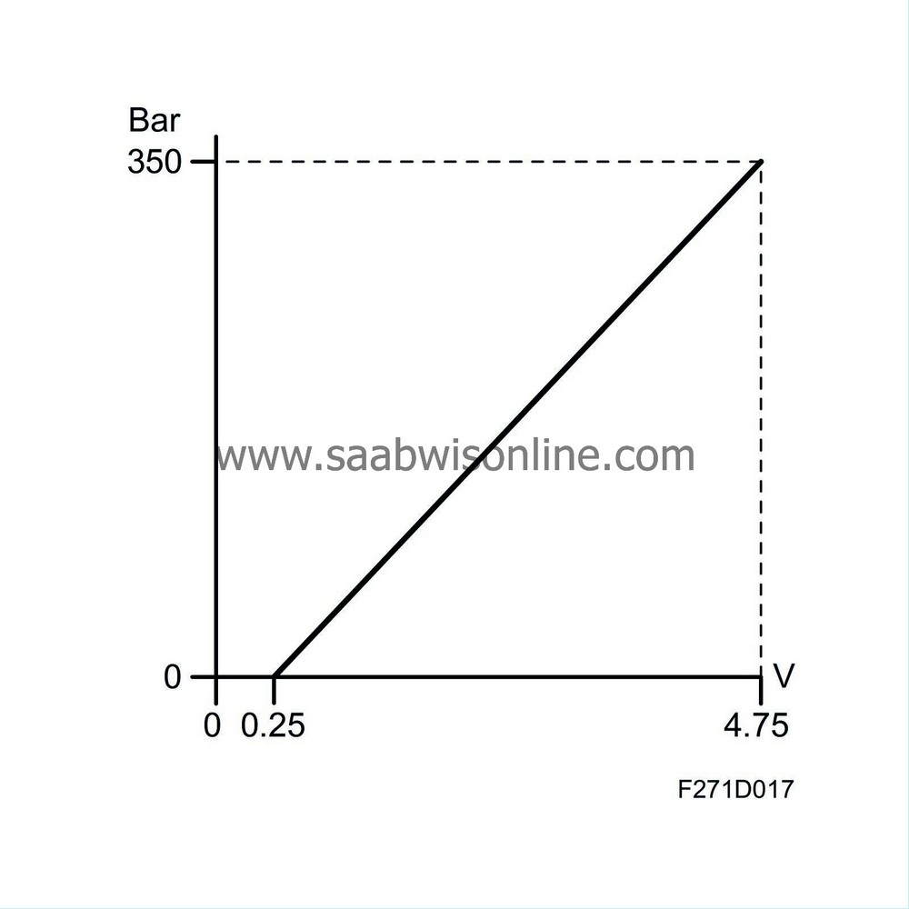
The pressure sensor consists of a silicone-based element that uses a piezoelectric operating principle involving the registering of an analogue output signal. When brake fluid pressure increases, the charge distribution in the element changes and the voltage becomes higher 0.25V-4.75V.
The signal voltage is amplified in the sensor and registered by the control module. The voltage corresponds to the pressure in the brake system.
| Warnings and indicator lights |
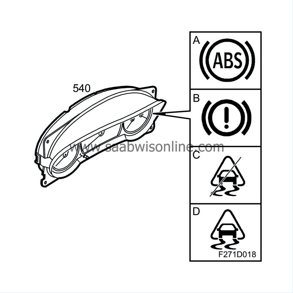
In certain situations, the TCS/ESP control module sends information regarding abnormal system function. This is displayed in the MIU or SID according to the following.
MIU
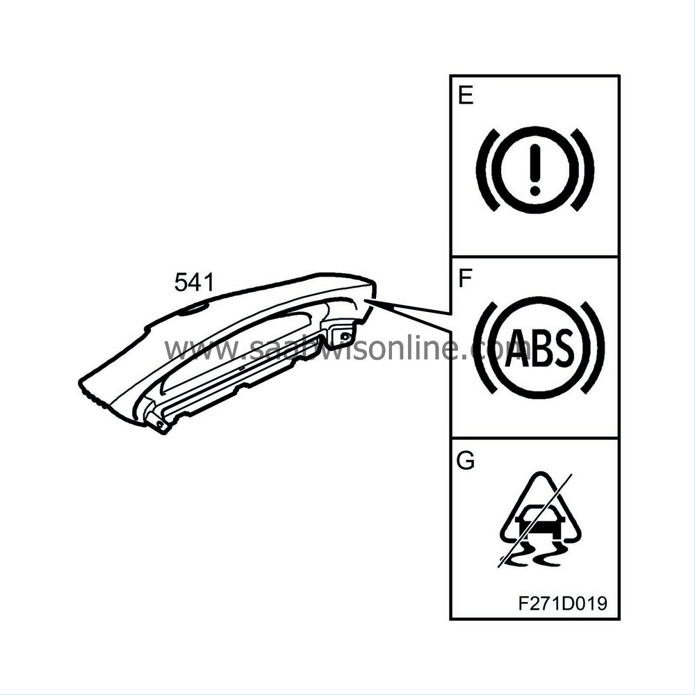
SID
| A. |
ABS - Warning, anti-lock brakes
The symbol lights when a fault is detected in the ABS system. |
|
| B. |
Foot brake, warning
Symbol and warning text light if EBD fault is detected or if the brake fluid level is too low |
|
| C. |
TCS OFF or ESP OFF
This symbol lights when the system is disengaged, with the TCS/ESP button or if a system fault is detected. |
|
| D. |
TCS or ECP indicator light
The symbol lights during system regulation. |
|
| E. |
Foot brake, warning
Symbol and warning text light if EBD fault is detected or if the brake fluid level is too low |
|
| F. |
ABS not functioning Contact workshop
The brake system functions without ABS function. Check the brake fluid level in the reservoir. |
|
| G. |
Anti-spin/Anti-skid not functioning
Contact a workshop. The symbol and text are displayed when system fault is detected. |
|

