SID, display and buttons, detailed description
|
|
SID, display and buttons, detailed description
|
Functions in SID
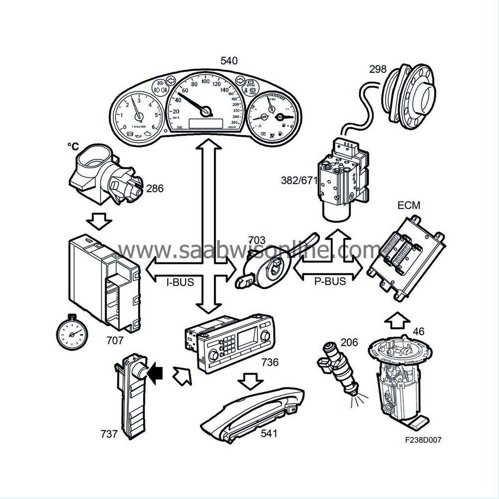
SID displays information on the following vehicle functions to the driver and passenger:
|
•
|
Trip computer information and settings
|
|
•
|
Warning & indicator messages
|
|
•
|
Time and date (from BCM)
|
|
•
|
Outside temperature (from BCM)
|
|
•
|
Navigation symbols (direction arrows, etc, only on ICM 3)
|
|
•
|
Radio and CD information
|
|
•
|
Telephone information (symbols and text messages)
|
|
•
|
Alarm indicator (if alarm fitted), LED on back of SID
|
SID stores all the characters and symbols used and displayed by SID. All text information is stored in ICM (infotainment display panel) and SID creates the text and symbol images to be shown.
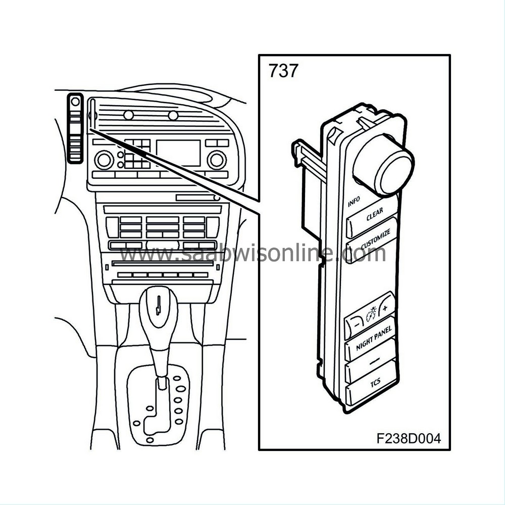
Functions in SIDC (SID control panel)
SIDC is used to
|
•
|
Adjust the brightness of the instrument illumination
|
|
•
|
Switch between SID functions
|
|
•
|
Adjust customer settings
|
|
•
|
Turn on or off TCS or ESP function
|
|
•
|
Turn on or off extra equipment
|
|
•
|
Night Panel (extinguishes certain parts of instrument illumination)
|
|
•
|
Clear (to clear a setting or message)
|
Functions in ICM (infotainment control panel)
ICM 1, 2 and 3 have a control panel for audio, telephone and navigation. ICM shares some logic functions with the radio main unit, but it is the overall control unit for navigation and communication. ICM 0 is in cars without an audio system and is a control module without keypad.
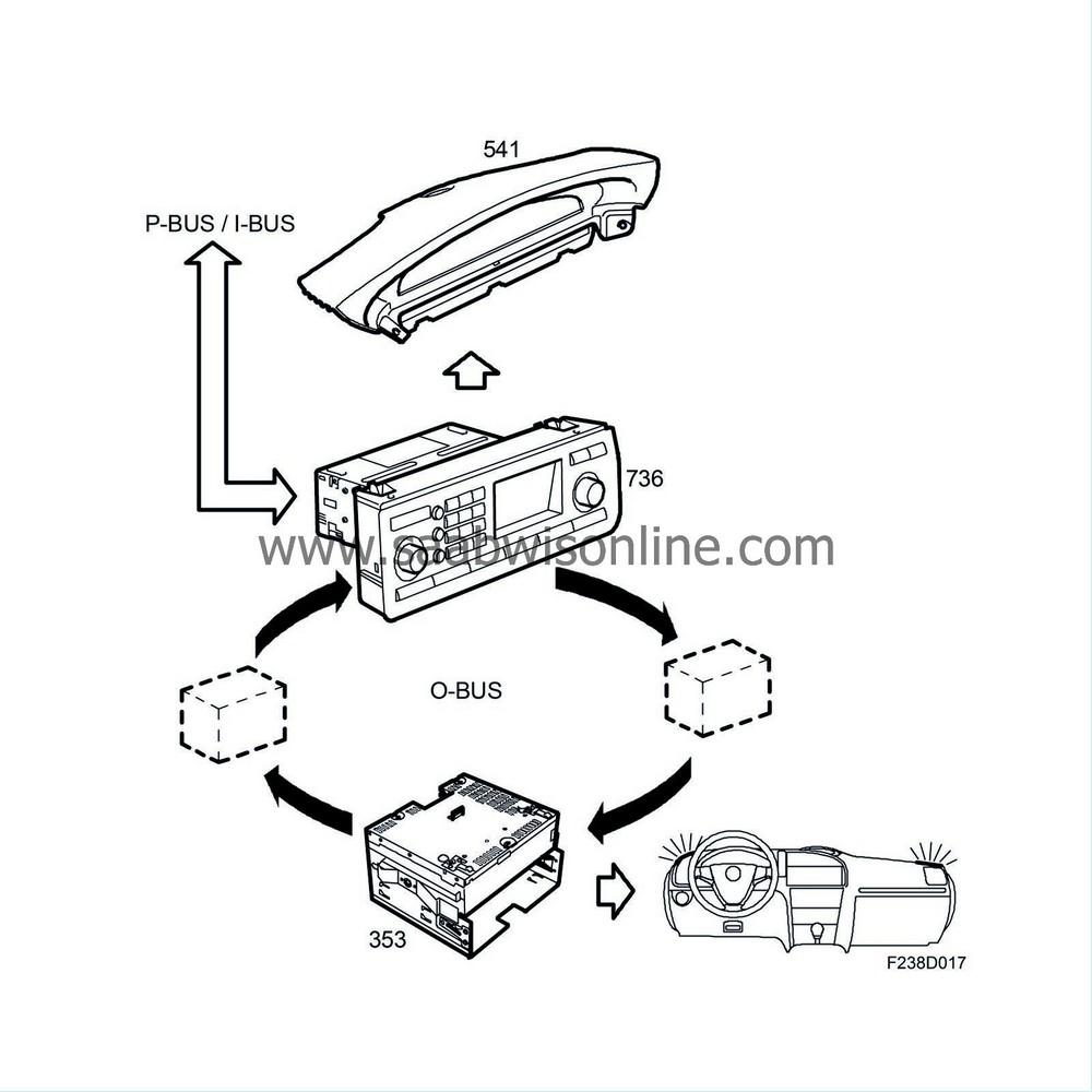
ICM is the control unit for the O-bus (Optic bus), which means that it controls all the units on the O-bus and is the gateway between the O-bus and the electric buses (P and I-buses).
ICM is the control unit for SID and SIDC.
ICM controls mainly the following functions:
|
•
|
Trip computer functions
|
|
•
|
Warning and indicator messages, language and units.
|
SID will display a text message and a symbol when it is time for service:
|
•
|
Time for service. Contact service.
|
The service message on the display can be reset using the SID control panel (SIDC). Press the CUSTOMIZE button, select "System settings" and then "Service Info" from the menu. Finally, select "Reset Service Ind." from the "Service Info" menu. The service message will be reset after pressing the INFO knob.
From the "Service Info" menu, you can select:
|
•
|
Service data showing oil quality 0-100%.
|
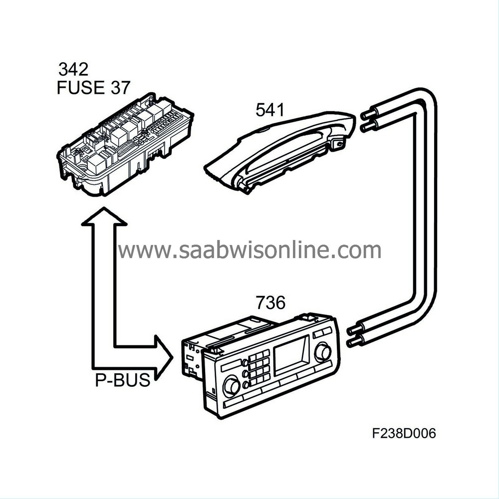
The car is put in transport mode by removing fuse 37 from the underhood electrical centre (UEC) and then turning the ignition key to ON.
The message "Transport Fuse Removed" will be displayed on SID when transport mode has been activated.
The following trip computer functions are available:
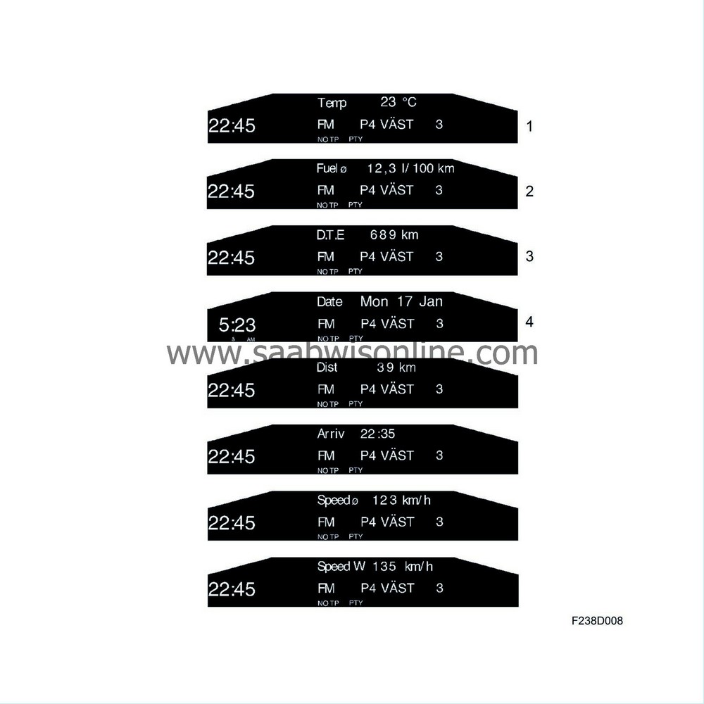
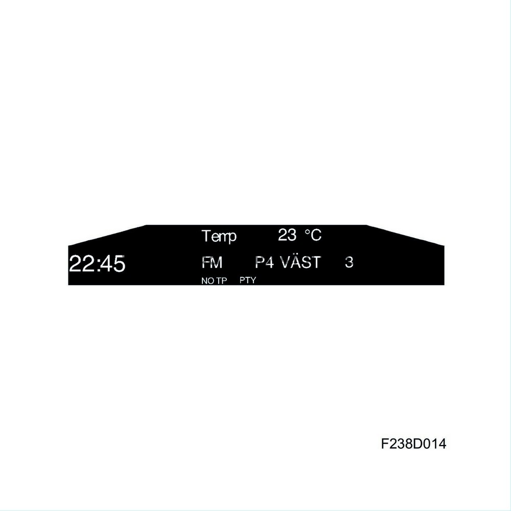
SID1
|
•
|
TEMP (outside temperature via BCM)
|
|
•
|
FUEL Ø (average fuel consumption)
|
|
•
|
DTE (distance to empty).
|
SID2
|
•
|
TEMP (outside temperature via BCM)
|
|
•
|
FUEL Ø (average fuel consumption)
|
|
•
|
DTE (distance to empty).
|
|
•
|
DIST (distance remaining). This function can also be used as a tripmeter.
|
|
•
|
ARRIV (estimate time of arrival)
|
|
•
|
SPEED Ø (average speed)
|
|
•
|
SPEED W (speed warning)
|
After starting the engine, the function being used when the engine was last turned off will be displayed with the following exceptions:
|
•
|
TEMP will be shown if it is between -3°C and +3°C.
|
|
•
|
DTE will be shown if it is 50 km or less.
|
TEMP will always be shown when the outside temperature rises or falls to within the interval -3°C and +3°C.
ICM controls the instrument and button illumination with the help of:
|
•
|
Brightness control buttons (rheostat function) on SIDC.
|
|
•
|
Light sensor on rear of SID that measures the ambient light from the front.
|
ICM uses these values when calculating a suitable brightness for the instrument and button illumination. ICM transmits the bus message "Instrument illumination, rheostat value" with a value between 0-100% on the I-bus.
The brightness control comprises a +/- switch that provides ICM with information on the driver's choice of instrument illumination. SIDC transmits the current button press to ICM, which increases or decreases the rheostat value accordingly.
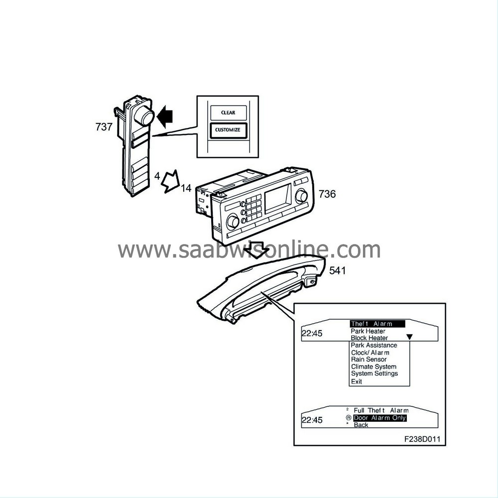
A PWM signal from SIDC on pin 4 to ICM pin 14 indicates the button (+/-) that has been pressed. This signal is a 5V 960Hz square wave with pulse ratio 40% for the up button (+) and 60% for the down button (-). See the
SID control panel
table.
The light sensor that measures brightness from the front is fitted to the back of SID together with the alarm LED. The light sensors have a measuring range between 0 and 40000 Lux.
On the SID unit is an LED indicating the state of the alarm. The LED is located on the back of SID next to the light sensor, which measures the ambient light from the front. BCM activates the alarm indicator LED via a wire.
Night Panel is used to minimise distracting light and provide an agreeable illumination in the cabin. When Night Panel is active, expendable information should be turned off and the brightness of the button illumination turned down.
The following will happen when the NIGHT PANEL button on SIDC is pressed:
|
•
|
The brightness of the button illumination will be reduced (from min 65% of max rheostat level).
|
|
•
|
The display lighting in SID and ICM will be extinguished.
|
|
•
|
All gauges on the main instrument unit except the speedometer (which is illuminated up to 140 km/h (90 mph)) will be extinguished. This function can also be adjusted to full scale lighting using the diagnostic tool.
|
The tachometer, turbo boost, fuel and temperature gauge needles will fall to their rest position once the illumination has been extinguished.
The following gauges/displays will individually return to normal display:
|
•
|
Turbo boost gauge in case of a vault. The engine control module will determine whether the gauge should be activated.
|
|
•
|
Right-hand speedometer graduation if the vehicle speed exceeds a pre-programmed limit.
|
|
•
|
Tachometer if the engine speed exceeds a pre-programmed limit.
|
|
•
|
Fuel gauge if the fuel quantity in the tank is less than 12 litres.
|
|
•
|
Temperature gauge if the engine temperature exceeds a pre-programmed limit (different limits for petrol and diesel engines).
|
|
•
|
The gear selector display will light up if the gear selector is not in D position.
|
|
•
|
Tripmeter and odometer displays if the CLEAR button is pressed for 20 seconds.
|
SID and ICM displays will light up if a CHECK function is activated. After confirmation from the driver, the display will be extinguished again unless the NIGHT PANEL button has been pressed.
SID and ICM displays light up if a button on SIDC has been pressed or if an audio function has been changed.
Night Panel is only active with the ignition key in ON position.
Customer settings are carried out in three stages:
|
1.
|
Press the CUSTOMIZE button.
|
|
2.
|
Navigate to correct menu using the INFO button.
|
|
3.
|
Press in the INFO knob to confirm a selection or press the CLEAR button to cancel a selection.
|
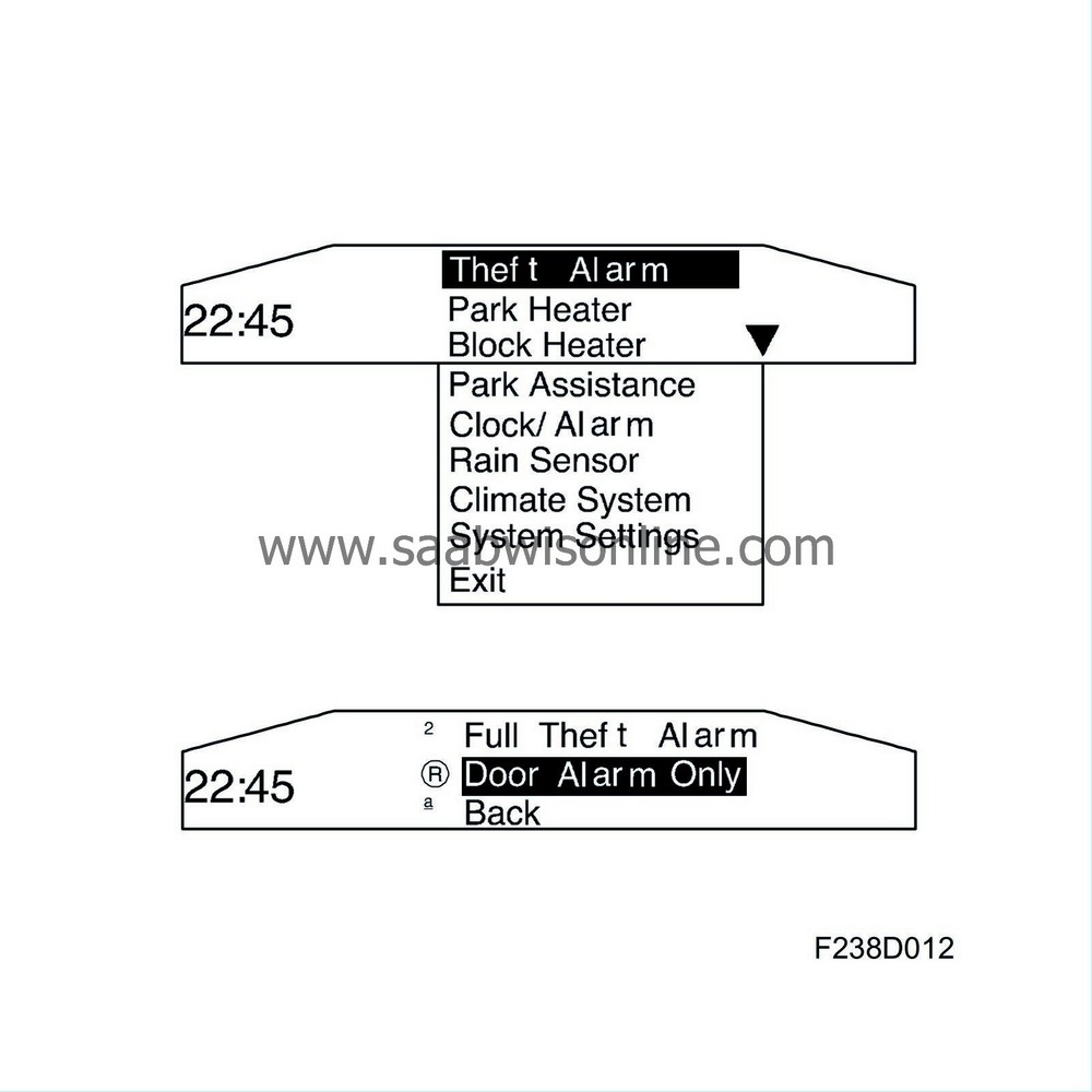
To exit from "Customer settings", navigate to Exit and press the INFO knob.
Further information on customer settings is available from the respective section in the Owner's manual.
The number of available selections in the menu depends on the car's equipment level. All the selections for the car are available when the ignition is on. To add or remove a function, e.g. if an accessory has been installed, the function will not be shown without first programming it with the diagnostic tool. Go to Add/Remove in the diagnostic tool menu and follow the instructions.
With the ignition key in LOCK position, there will be a limited choice of available selections, e.g. parking heater and alarm.
Setting a value:
|
1.
|
Select one of the functions with the INFO knob.
|
|
2.
|
Keep the INFO knob pressed until an acknowledgement signal is heard.
|
|
3.
|
Turn the INFO knob to change the value. The value can be deleted with the CLEAR button.
|
|
4.
|
Complete the setting by pressing the INFO knob.
|
|
Warning and indicator messages
|
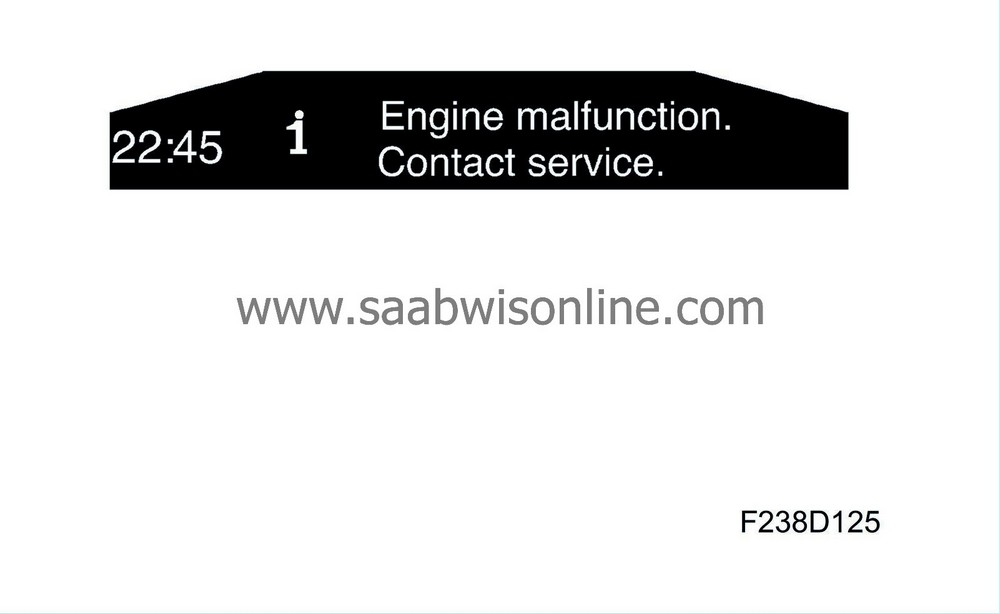
SID displays warning and indicator messages to inform the driver with symbols and text. These messages are stored in ICM. The symbols are either red or orange. The red symbols cannot be cleared from SID as they are considered as important warning messages.
The following warning and indicator messages can be displayed on SID:
Engine and gearbox
|
•
|
Engine malfunction. Contact service.
|
|
•
|
Oil pressure low. Make a safe stop. Turn off engine.
|
|
•
|
Low engine oil level. Fill oil now.
|
|
•
|
Water in fuel. Contact service.
|
|
•
|
Hot engine. Make a safe stop. Run engine on idle.
|
|
•
|
Coolant level low. Refill needed.
|
|
•
|
Tap brakes lightly before using cruise control.
|
|
•
|
Gearbox malfunction. Limited performance. Contact service.
|
|
•
|
Gearbox too hot. Make a safe stop. Open hood to cool down.
|
Charging systems
|
•
|
Battery not charging. Make a safe stop. Contact service.
|
Lighting and signalling system
|
•
|
Rear fog light failure.
|
|
•
|
Left rear turn indicator failure.
|
|
•
|
Right rear turn indicator failure.
|
|
•
|
Left brake light failure.
|
|
•
|
Right brake light failure.
|
|
•
|
Left front turn indicator failure.
|
|
•
|
Right front turn indicator failure.
|
|
•
|
Right low beam failure.
|
|
•
|
Left high beam failure.
|
|
•
|
Right high beam failure.
|
|
•
|
High mounted brake light failure.
|
|
•
|
Right rear position light failure.
|
|
•
|
Left rear position light failure.
|
|
•
|
Headlamp levelling malfunction. Contact service.
|
Wash/wipe systems
|
•
|
Washer fluid level low. Refill needed.
|
Saab Park Assistance (SPA)
|
•
|
Parking Assistance malfunction. Contact service.
|
|
•
|
Parking assistance sensor disturbed.
|
Seat belt system
|
•
|
Rear right seat backrest unlocked.
|
|
•
|
Rear left seat backrest unlocked.
|
Airbag system
|
•
|
Airbag malfunction. Contact service.
|
Theft protection, doors and locks
|
•
|
Immobilizer failure. Retry to start. Contact service.
|
|
•
|
Key not accepted. Contact service.
|
|
•
|
Lock engaged. Pull out key. Turn steering wheel. Retry start.
|
|
•
|
Steering lock malfunction. Make a safe stop. Contact service.
|
|
•
|
Alarm activated during last arming period.
|
|
•
|
Theft protection failure. Contact service.
|
|
•
|
X: standard key Y: valet key Key No: Z
|
|
•
|
Remote control battery low. Replace battery.
|
Brakes
|
•
|
Antilock brake malfunction. Contact service.
|
|
•
|
Stability control failure. Contact service.
|
|
•
|
Traction control failure. Contact service.
|
|
•
|
Brake malfunction. Make a safe stop. Contact service.
|
|
•
|
Brake fluid level low. Make a safe stop. Contact service.
|
Other
|
•
|
Time for service. Contact service.
|
|
•
|
Incorrect part detected. Contact service.
|
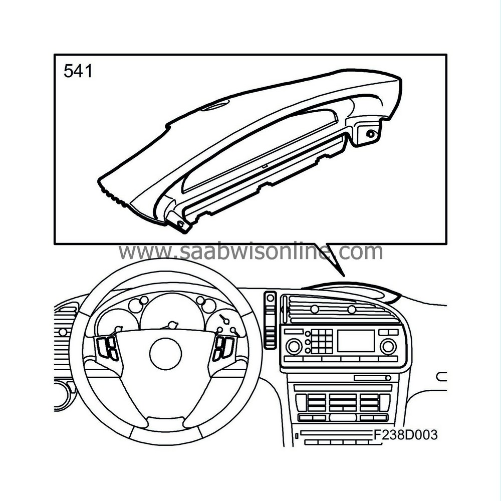
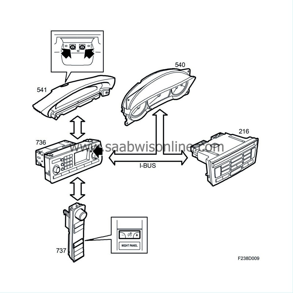
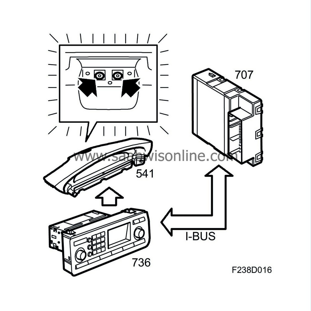
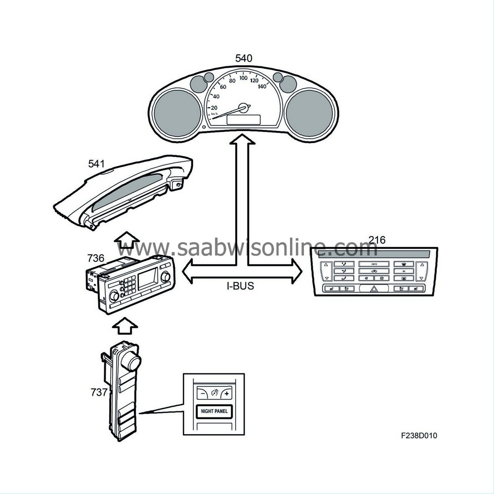
When a message is displayed in SID (541) it is indicated with an acoustic signal in the dashboard speakers. If several messages are displayed then only the first message is indicated with an acoustic signal.
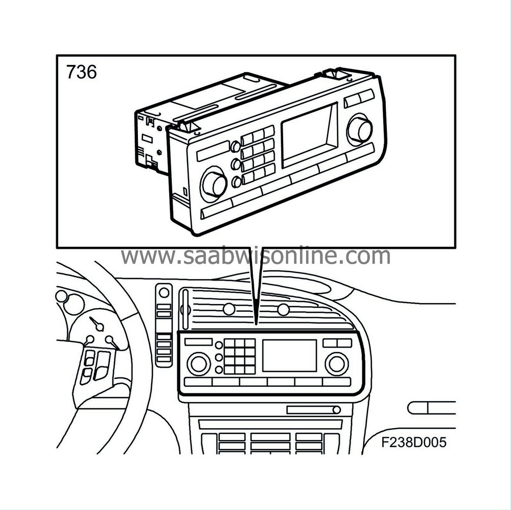
ICM (736) is a control unit for warning and indicator sounds, which means that it manages the prioritising and activates EHU (353).
ICM receives a bus message to generate an acoustic signal and in turn transmits a bus message on the O-bus requesting an acoustic signal in the loudspeakers. EHU (the radio main unit) receives the bus message and sends an acoustic signal to the front speakers.
An EHU (353) is also fitted in cars without audio system in order to generate warning and indicator sounds.
|
•
|
Basic menu
|
|
|
3.
|
Audio information (controlled via ICM, the infotainment control panel)
|
|
•
|
Trip computer information
|
|
•
|
Warning and indicator messages
|
|
•
|
Customer settings
|
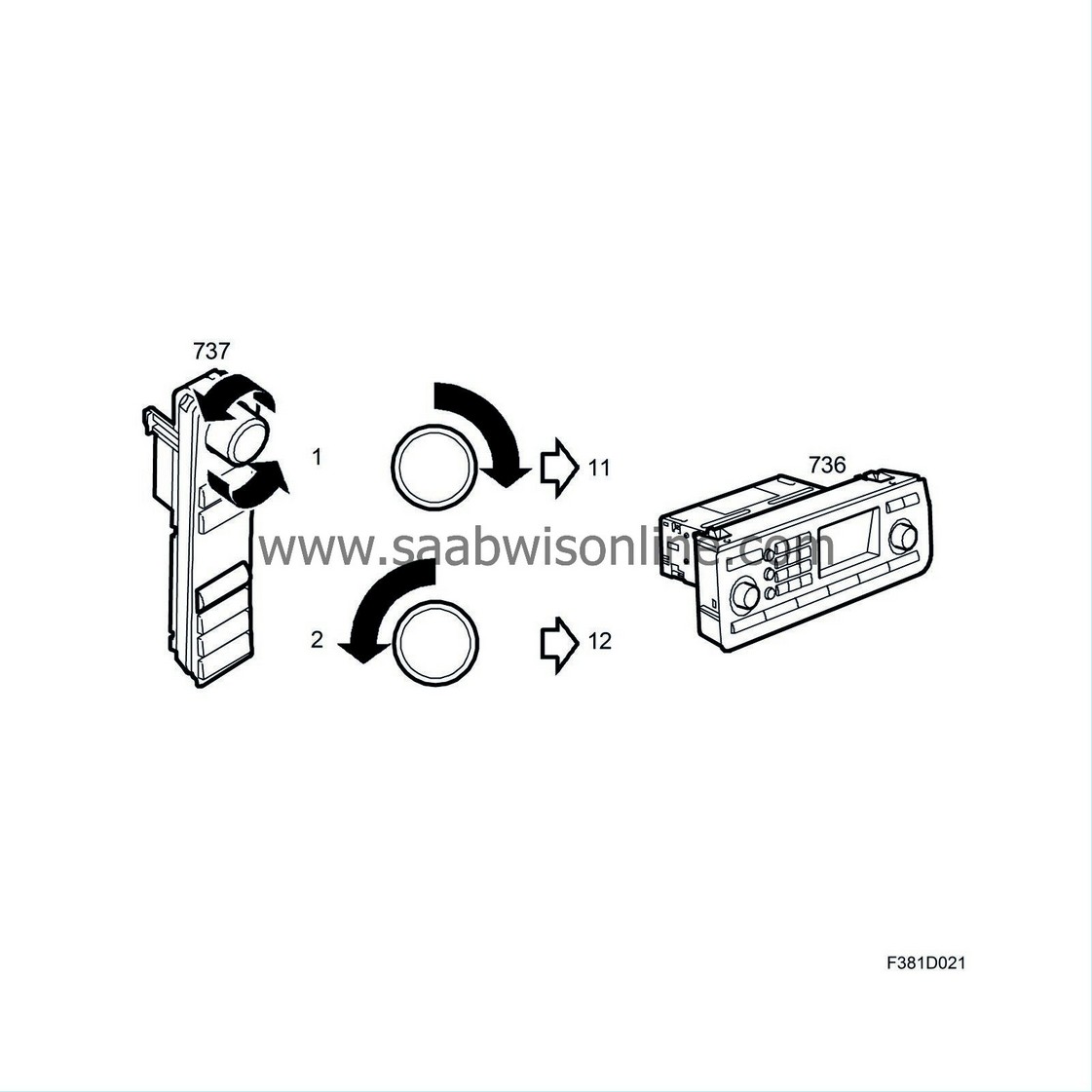
The SID unit control panel communicates with the ICM on a wire and each button press or turn of the INFO knob is registered by the ICM. When turning the INFO knob in one direction, SIDC pin 1 will ground ICM pin 11, and when turning it in the other direction, SIDC pin 2 will ground ICM pin 12. The signal after pressing a button is sent from SIDC pin 4 to ICM pin 14. The signal is a 5 V, 960 Hz square wave (PWM), where the pulse ratio varies between 10% and 90%.
|
SIDC button
|
Pulse ratio (%)
|
|
- Extra equipment
|
10
|
|
ESP or TCS
|
20
|
|
Night Panel
|
30
|
|
Brightness control +
|
40
|
|
No button pressed
|
50
|
|
Brightness control -
|
60
|
|
CUSTOMIZE
|
70
|
|
CLEAR
|
80
|
|
INFO knob (press function)
|
90
|
INFO knob
The INFO knob has a rotate and press function. It is used to activate menus and switch between them. The INFO knob can be turned to 18 distinctive positions. The press function is used for confirmation when making settings. SIDC sends a 5V 960Hz PWM signal with a pulse ratio of 90% from pin 4 to ICM pin 14 when activating the press function.
The rotate function is supplied with 5V on pin 1 from ICM pin 11 and with 5V on pin 2 from ICM pin 12. SIDC grounds the respective pins in a certain order when turning the knob in one direction and in the opposite order when turning it in the other direction. ICM registers how far the knob is turned and in which direction.
CUSTOMIZE button
Customer settings are done using the CUSTOMIZE button. A number of different menu choices for navigation are shown when the CUSTOMIZE button is pressed. The number of menu choices depends on the equipment level of the car. The following choices may be available:
Pressing the CUSTOMIZE button will make SIDC send a 5V 960Hz PWM signal with pulse ratio 70% on pin 4 to ICM pin 14.
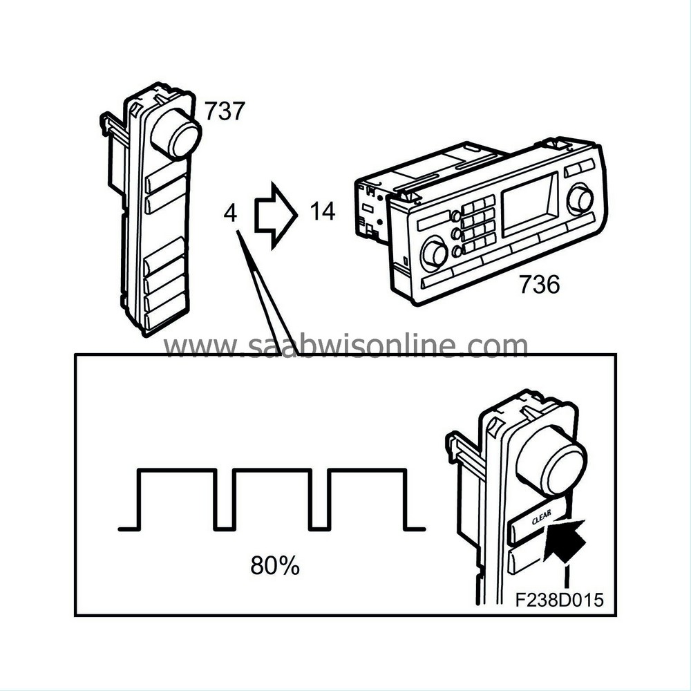
CLEAR button
The CLEAR button is used to delete a setting. To clear a message on SID, press the CLEAR button for about three seconds and it will disappear. If the message is in red, only the text can be deleted, the symbol cannot be cleared. Pressing the CLEAR button will make SIDC send a 5V 960Hz PWM signal with pulse ratio 80% from pin 4 to ICM pin 14.
ESP or TCS button
Pressing the button will disengage the functions and display a signal on the main instrument unit. It is not possible to disengage this function if the vehicle speed is exceeding 60 km/h. SIDC sends a 5V 960Hz PWM signal with pulse ratio 20% from pin 4 to ICM pin 14.
- Extra equipment
Extra equipment such as spotlights can be activated with this switch. SIDC sends a 5V 960Hz PWM signal with pulse ratio 10% from pin 4 to ICM pin 14.
Brightness control (rheostat function)
This switch can be used to adjust the instrument illumination. ICM controls the cabin lighting after allowing not only for the rheostat control but also for the light sensor on SID that measures the backlight. The switch provides ICM with information on the driver's chosen instrument illumination setting. A PWM signal from SIDC pin 4 to ICM pin 14 indicates the button (+/-) being pressed. The signal is 5V 960Hz PWM with pulse ratio 40% for the up button (+) and 60% for the down button (-).
Night panel
Extinguishes SID, ICM and main instrument unit displays except for the speedometer and reduces the brightness of the button illumination. See
Night Panel
. SIDC sends a 5V 960Hz PWM signal with pulse ratio 30% from pin 4 to ICM pin 14.
The SID unit control panel communicates with the ICM on a wire and each button press or turn of the INFO knob is registered by the ICM. When turning the INFO knob in one direction, SIDC pin 1 will ground ICM pin 11, and when turning it in the other direction, SIDC pin 2 will ground ICM pin 12. The signal after pressing a button is sent from SIDC pin 4 to ICM pin 14. The signal is a 5 V, 960 Hz square wave (PWM), where the pulse ratio varies between 10% and 90%.
|
SIDC button
|
Pulse ratio (%)
|
|
ESP or TCS
|
9
|
|
Soft top down
|
18
|
|
Soft top up
|
27
|
|
Night Panel
|
36
|
|
Brightness control +
|
45
|
|
No button pressed
|
54
|
|
Brightness control -
|
63
|
|
CUSTOMIZE
|
72
|
|
CLEAR
|
81
|
|
INFO knob (press function)
|
90
|
INFO knob
The INFO knob has a rotate and press function. It is used to activate menus and switch between them. The INFO knob can be turned to 18 distinctive positions. The press function is used for confirmation when making settings. SIDC sends a 5V 960Hz PWM signal with a pulse ratio of 90% from pin 4 to ICM pin 14 when activating the press function.
The rotate function is supplied with 5V on pin 1 from ICM pin 11 and with 5V on pin 2 from ICM pin 12. SIDC grounds the respective pins in a certain order when turning the knob in one direction and in the opposite order when turning it in the other direction. ICM registers how far the knob is turned and in which direction.
CUSTOMIZE button
Customer settings are done using the CUSTOMIZE button. A number of different menu choices for navigation are shown when the CUSTOMIZE button is pressed. The number of menu choices depends on the equipment level of the car. The following choices may be available:
Pressing the CUSTOMIZE button will make SIDC send a 5V 960 Hz PWM signal with a 72% pulse ratio from pin 4 to pin 14 of the ICM.
CLEAR button
The CLEAR button is used to delete a setting. To clear a message on SID, press the CLEAR button for about three seconds and it will disappear. If the message is in red, only the text can be deleted, the symbol cannot be cleared. Pressing the CLEAR button will make SIDC send a 5V 960 Hz PWM signal with an 81% pulse ratio from pin 4 to ICM pin 14.
ESP or TCS button
Pressing the button will disengage the functions and display a signal on the main instrument unit. It is not possible to disengage this function if the vehicle speed is exceeding 60 km/h. SIDC sends a 5V 960 Hz PWM signal with a 9% pulse ratio from pin 4 to ICM pin 14.
Soft top down
The soft top is lowered with this switch by pressing and holding it. The SIDC sends a 5V 960 Hz PWM signal with an 18% pulse ratio from pin 4 to pin 14 of the ICM.
Soft top up
The soft top is raised with this switch by pressing and holding it. The SIDC sends a 5V 960 Hz PWM signal with a 27% pulse ratio from pin 4 to pin 14 of the ICM.
Brightness control (rheostat function)
This switch can be used to adjust the instrument illumination. The ICM controls the cabin lighting after allowing not only for the rheostat control but also for the light sensor on the SID that measures the backlight. The switch provides the ICM with information on the driver's chosen instrument illumination setting. A PWM signal from pin 4 of the SIDC to pin 14 of the ICM indicates the button (+/-) being pressed. The signal is 5V 960 Hz PWM with a pulse ratio of 45% for the up button (+) and 63% for the down button (-).
Night panel
Extinguishes the SID, ICM and main instrument unit displays except for the speedometer and reduces the brightness of the button illumination. See
Night Panel
. The SIDC sends a 5V 960 Hz PWM signal with a pulse ratio of 36% from pin 4 to ICM pin 14.
Language
ICM texts are translated to a total of 7 different languages:
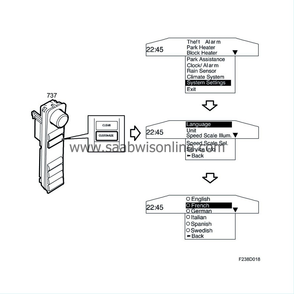
ICM is available in different language versions.
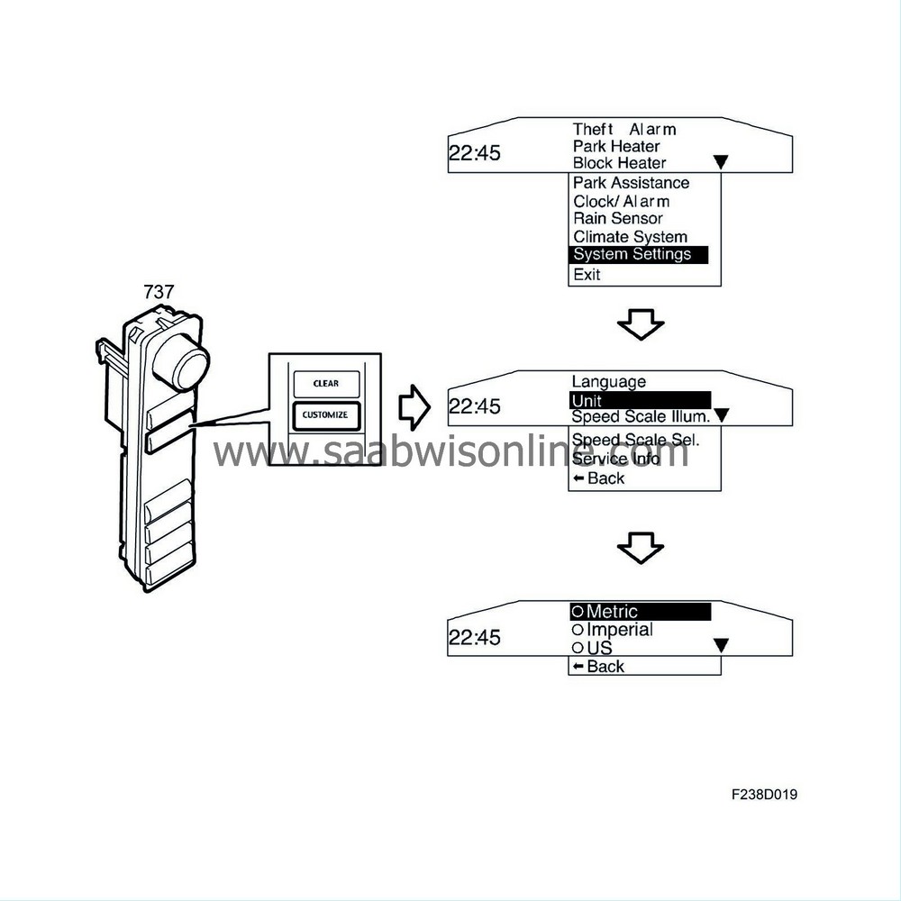
Units
Units are market-oriented but they can be changed using the CUSTOMIZE button in the
Customer Settings
menu.
The following units can be selected:
ICM contains a list of the control modules on the O-bus and can compare this list with incoming bus messages to determine the location of a break on the O-bus.
The diagnostic tool is used to update the list of control modules in ICM when a new control module is fitted to the O-bus.


