PRE-RELEASE
Timing cover in car
| Timing cover in car |
| To remove |
| 1. |
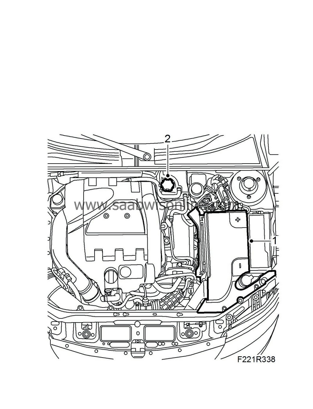
Remove the battery cover and the negative cable.
|
|||||||||||||||
| 2. |
Open the cap to the expansion tank, release any overpressure.
|
|
| 3. |
Raise the car.
|
|
| 4. |
Undo the right-hand side of the spoiler shield.
|
|
| 5. |
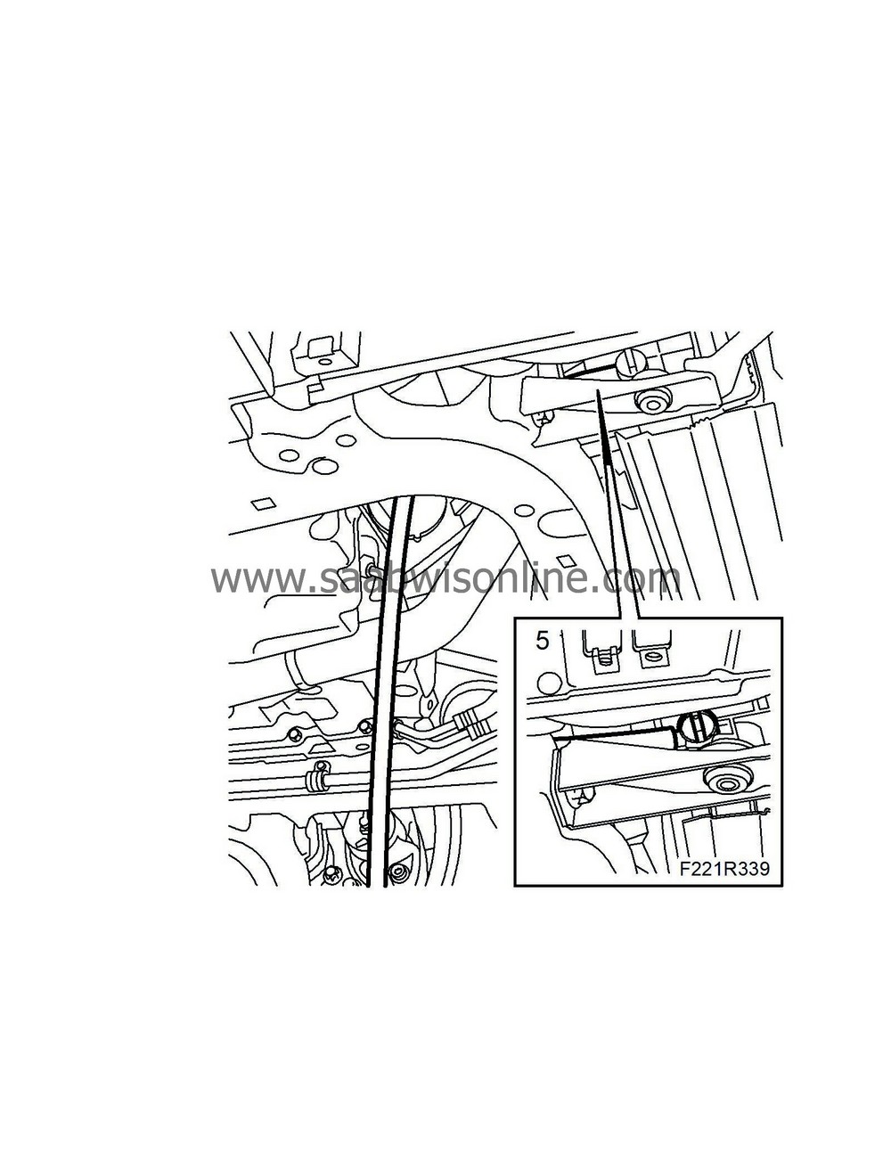
Place a suitable receptacle under the radiator. Connect a hose to the radiator and drain the coolant. Close the cock and refit the spoiler shield.
|
|
| 6. |
Lower the car.
|
||||||||||
| 7. |
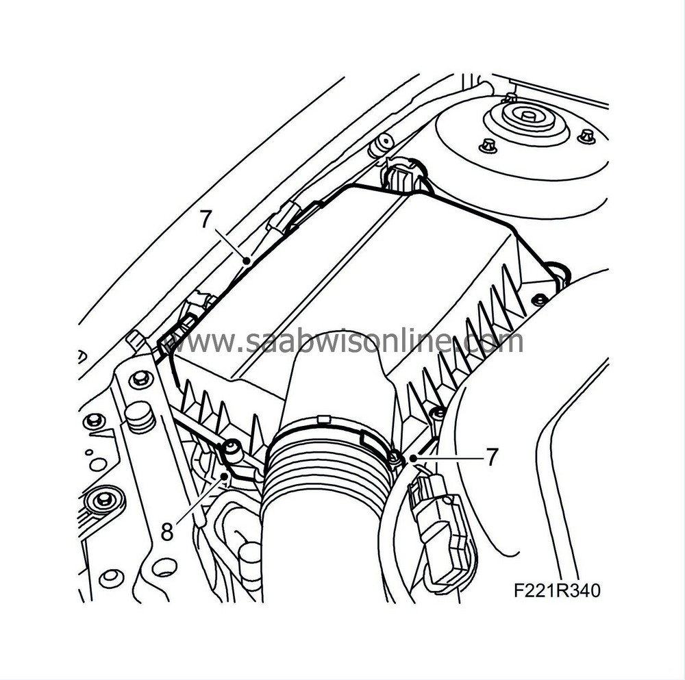
Remove the upper section of the air cleaner.
|
|
| 8. |
Remove the lower section of the air filter.
|
||||||||||
| 9. |
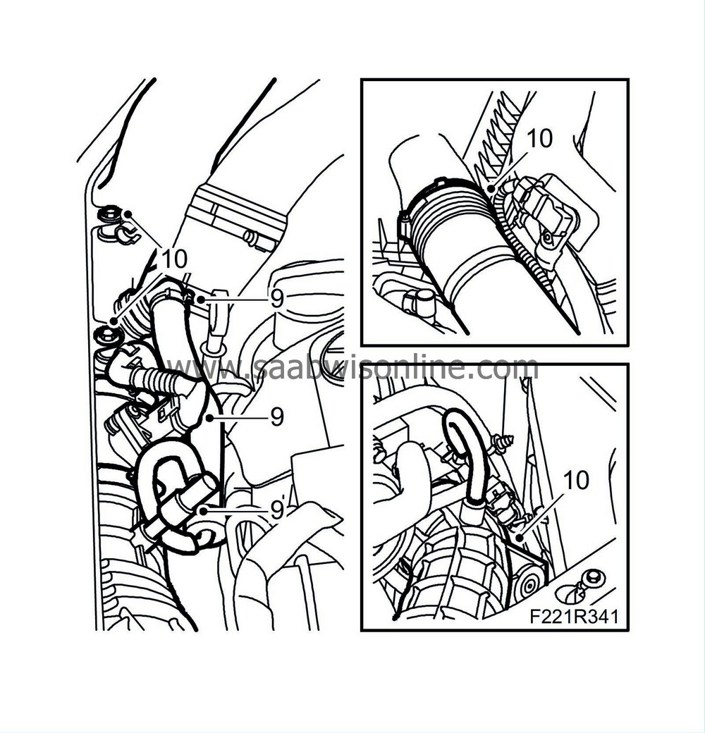
Unplug the mass air flow sensor connector. Detach the secondary air pipe, the delivery hose from the turbocharger intake manifold and the crankcase ventilation pipes.
|
|
| 10. |
Detach the turbocharger intake manifold from the air filter housing cover and the turbocharger.
|
|
| 11. |
Remove the upper engine cover.
|
|
| 12. |
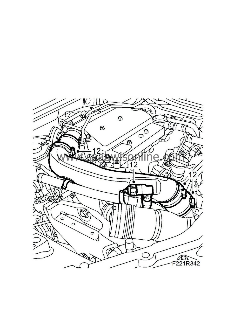
Remove the charge air pipe by first removing the clamps and the charge pressure sensor connectors. Detach the power steering line.
|
|
| 13. |
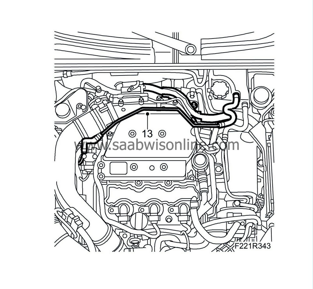
Remove the coolant return line by first removing the wiring harnesses.
|
|
| 14. |
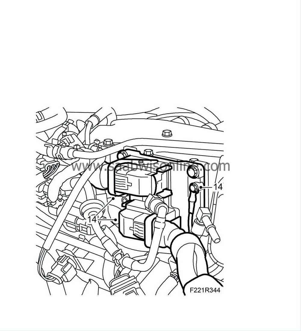
Remove the connector and the ground connection to the engine control module
|
|
| 15. |
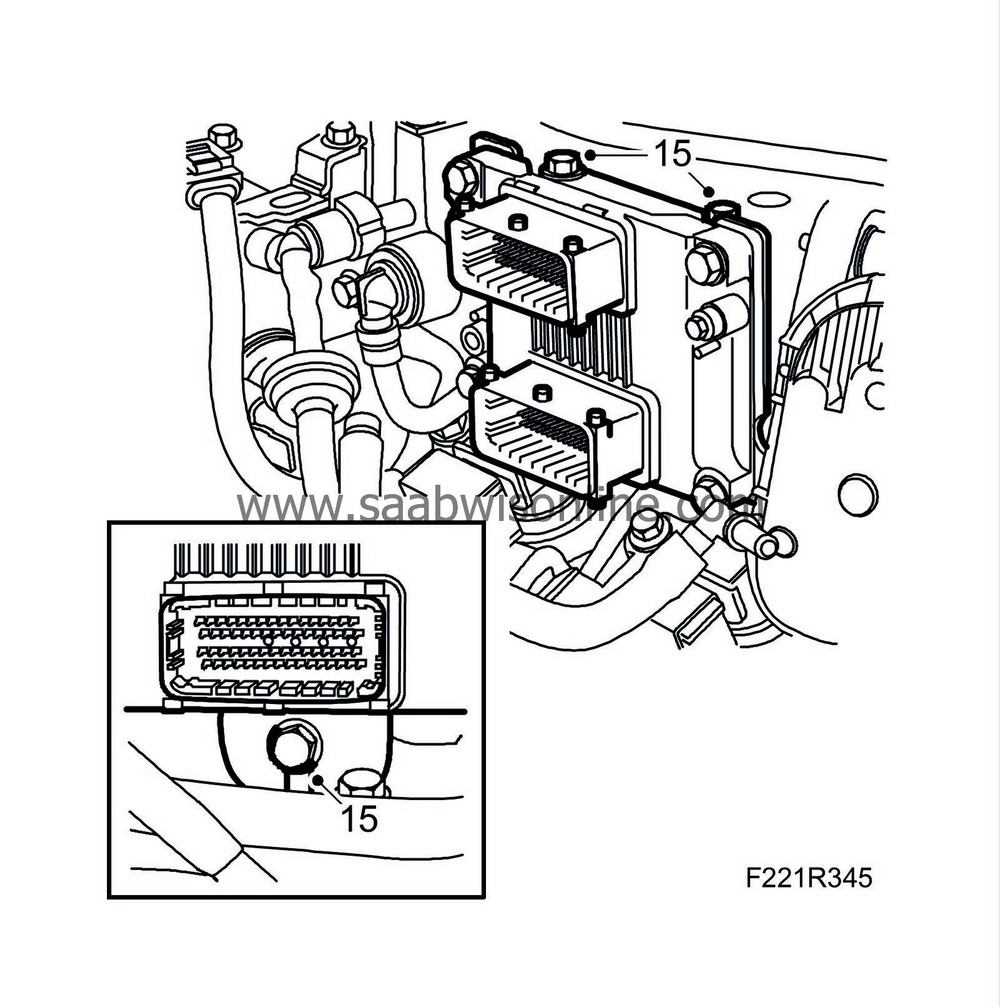
Remove the engine control module bolts.
|
|
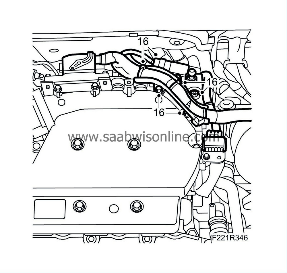
| 16. |
Remove the wiring harnesses holders by removing the cable duct, the connectors and the nut. Unplug the connector to the intake manifold pressure sensor. Remove the bolt, cable tie and connector.
|
|
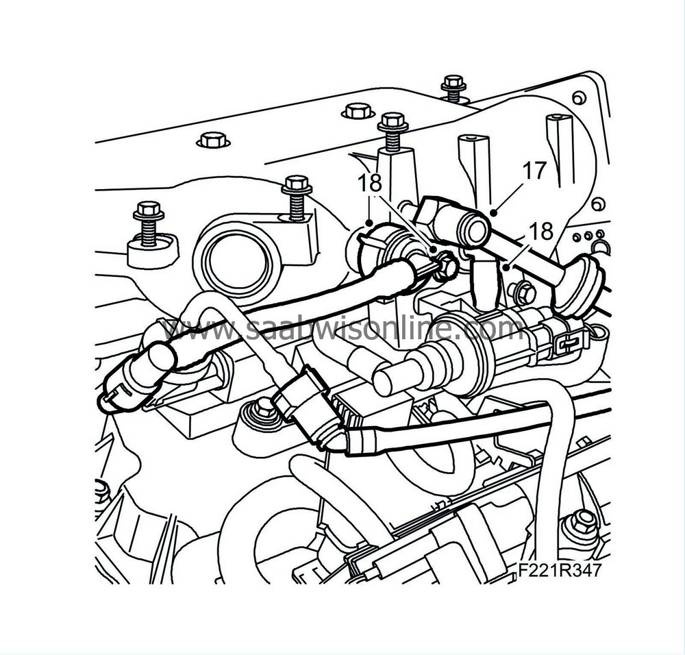
| 17. |
Undo the quick coupling and remove the vacuum line from the upper section of the intake manifold.
|
|
| 18. |
Remove the crankcase ventilation lines by removing the bolt and removing the holder.
|
|
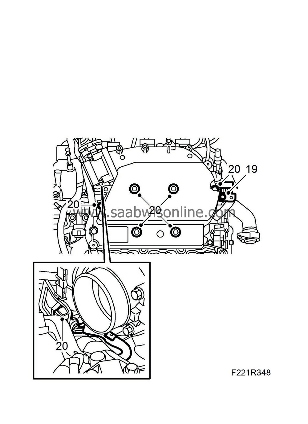
| 19. |
Remove the holder to the injector's connector.
|
|
| 20. |
Remove the throttle body connector and remove the upper section of the intake manifold.
|
||||||||||||||||||||||||
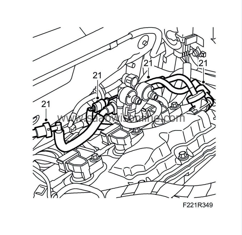
| 21. |
Undo the quick couplings and remove the bleeder valve plus lines.
|
|
| 22. |
Place a collecting pan under the car.
|
|
| 23. |
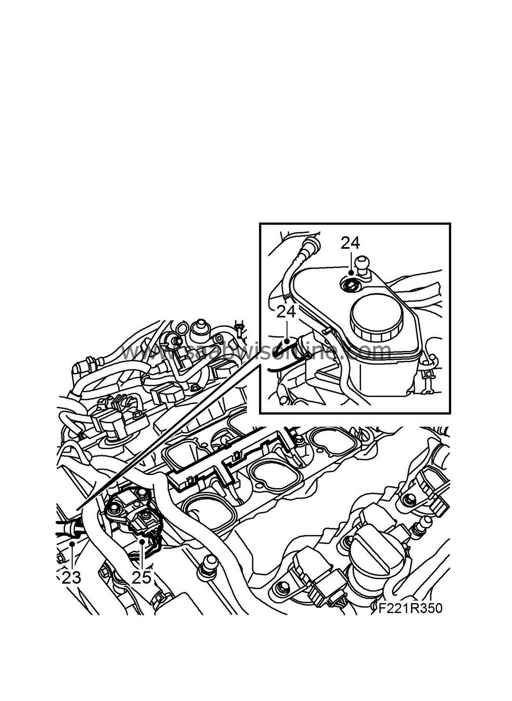
Detach the fuel line, wiping up any fuel spill with a cloth.
|
|
| 24. |
Remove the power steering reservoir by removing the bolt, return hose and clamp. Seal the hose and reservoir. Turn the reservoir to the side.
|
|
| 25. |
Unplug the connectors to the fuel pressure sensor.
|
|
| 26. |
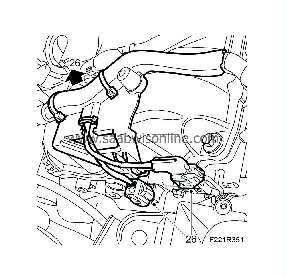
Remove the wiring harnesses from the cylinder head for cylinders 1-3-5. Unplug the camshaft position sensor connector, the connector to the camshaft setting valve and the holder.
|
|
| 27. |
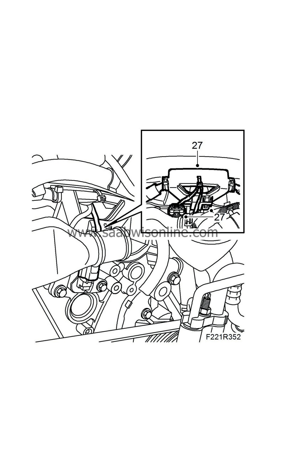
Remove the wiring harnesses from the cylinder head for cylinders 2-4-6. Unplug the camshaft position sensor connector, the connector to the camshaft setting valve and the holder.
|
|
| 28. |
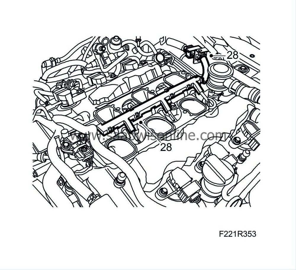
Remove the wiring harness for the injectors by first unplugging the injectors' connectors.
|
|
| 29. |
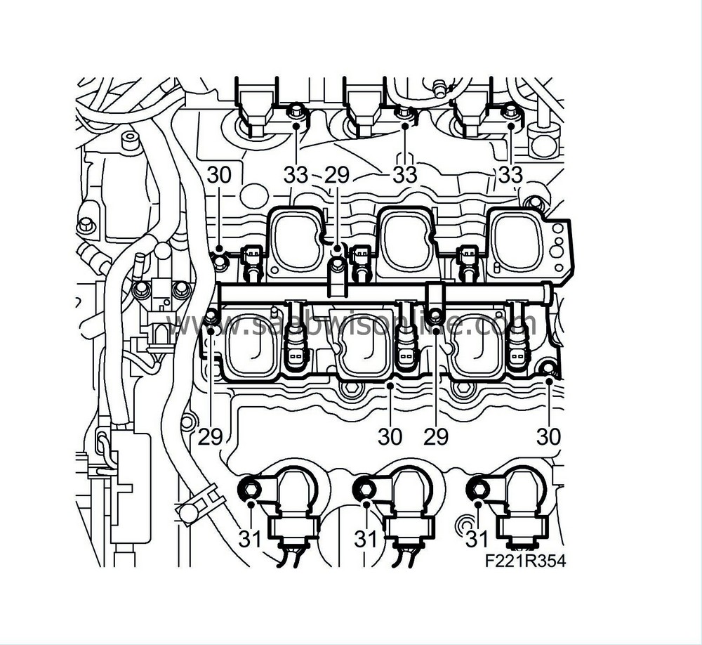
Remove the fuel rail with injectors.
|
|
| 30. |
Remove the lower section of the intake manifold. Seal the inlet ducts to the cylinder head with lintless rags.
|
|
| 31. |
Remove the ignition coils for cylinders 2-4-6 by first unplugging the connectors.
|
|
| 32. |
Remove the wiring harness holder from the camshaft cover for cylinders 1-3-5.
|
|
| 33. |
Remove the ignition coils for cylinders 1-3-5 by first unplugging the connectors.
|
|
| 34. |
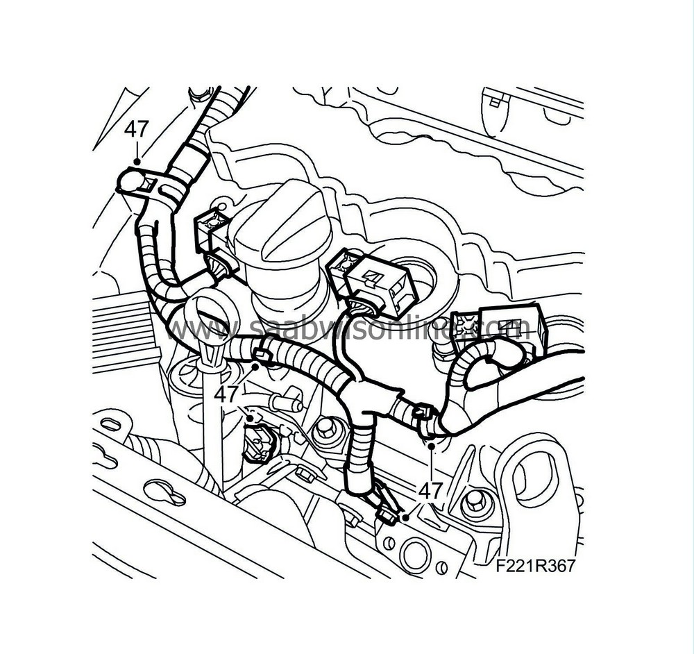
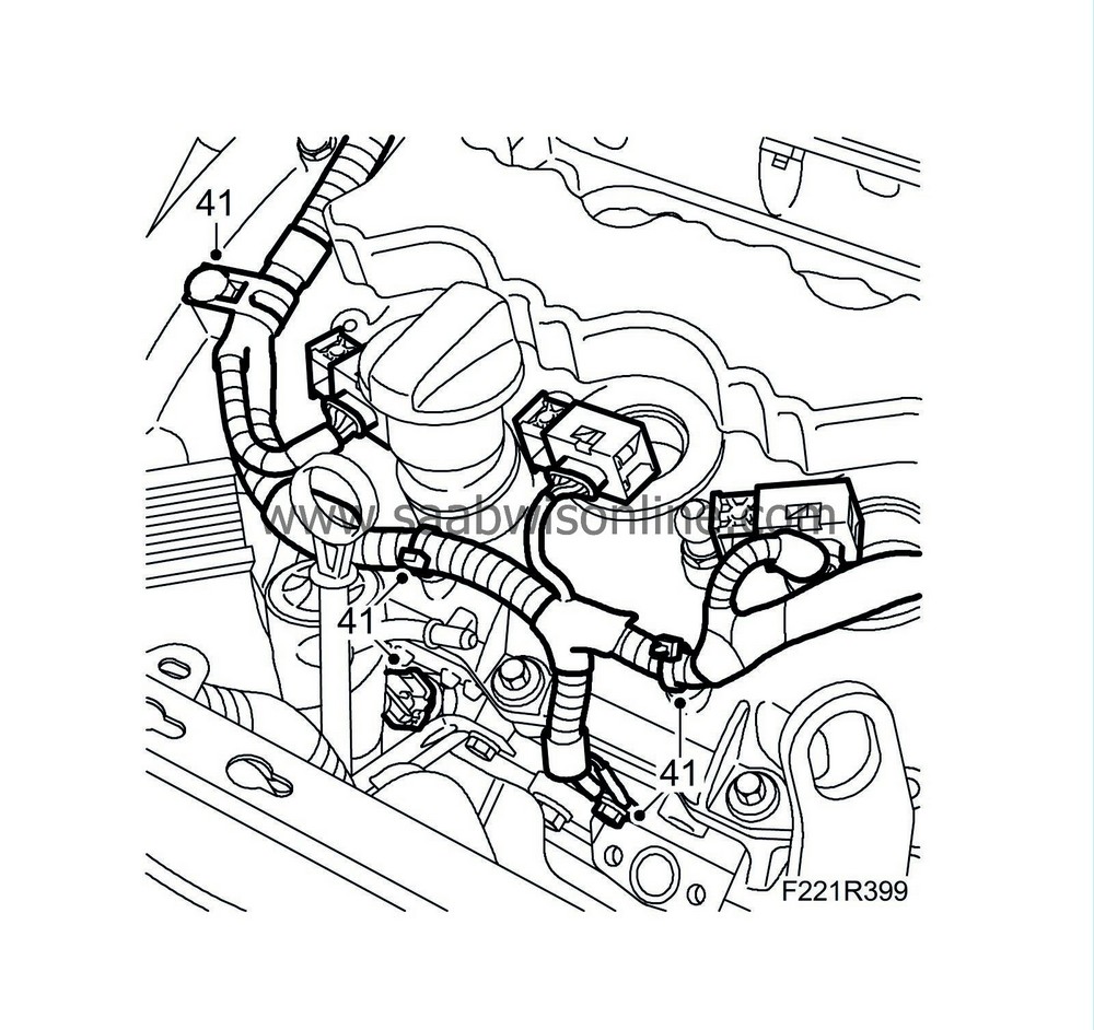
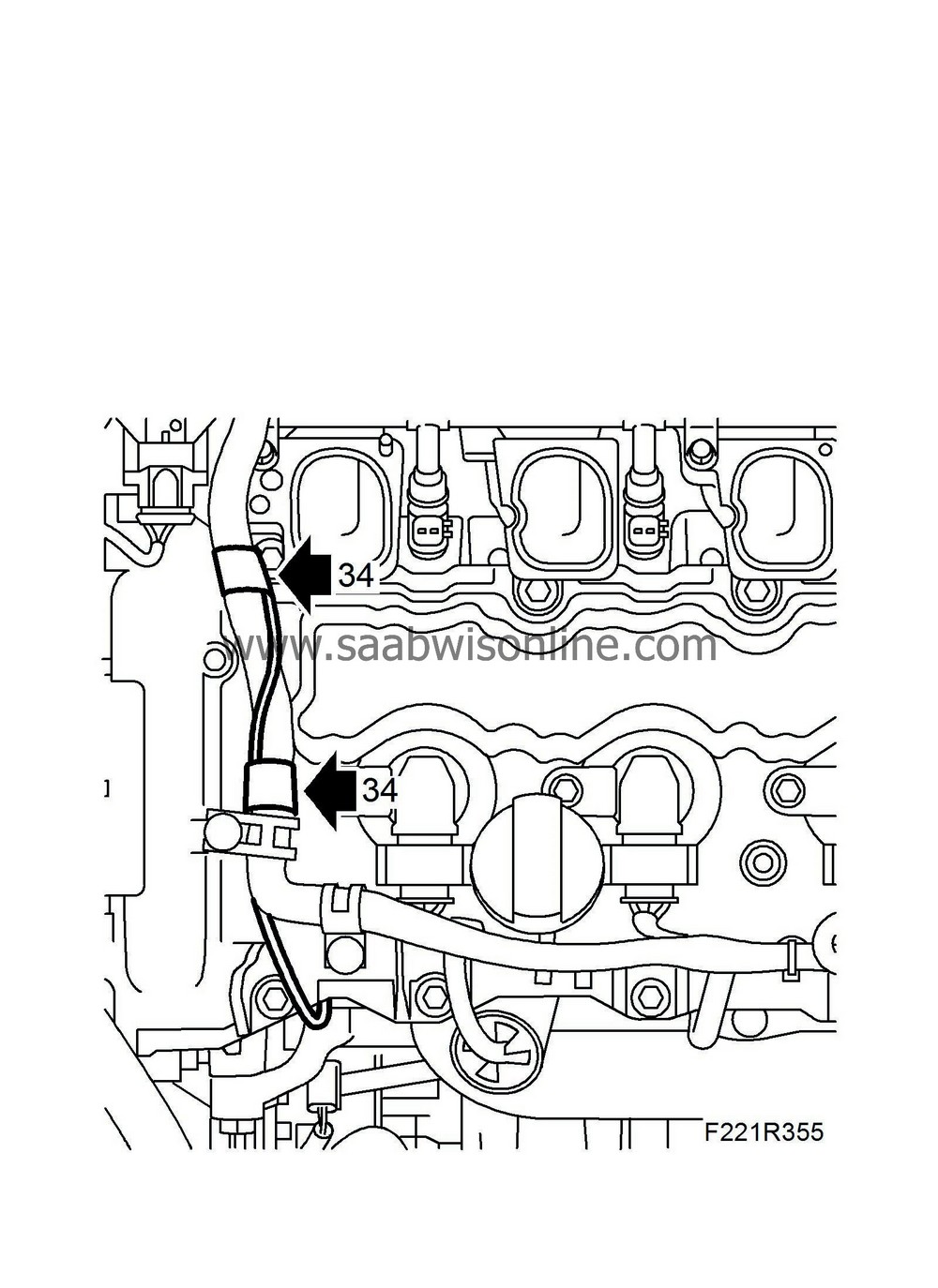
Remove the ground cable from the wiring harnesses by carefully cutting open the tape strip (arrows). Place the ground cable to one side.
|
|
| 35. |
Remove the wiring harnesses plus connectors. Remove the cable tie.
|
|
| 36. |
Remove
Battery cover, bottom section, B284
.
|
|
| 37. |
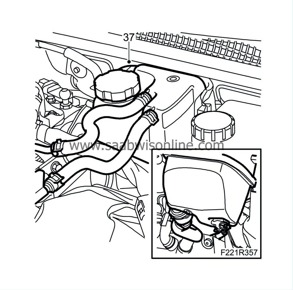
Loosen the expansion tank from the mounting.
|
|
| 38. |
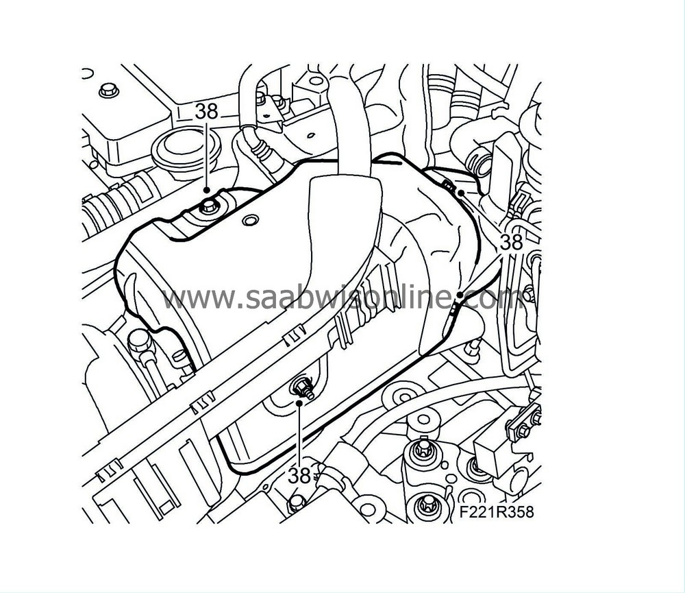
Remove the turbocharger heat shield panel.
|
|
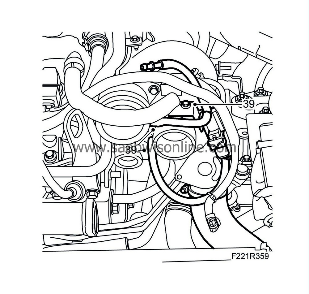
| 39. |
Remove the crankcase ventilation line from the turbocharger.
|
|
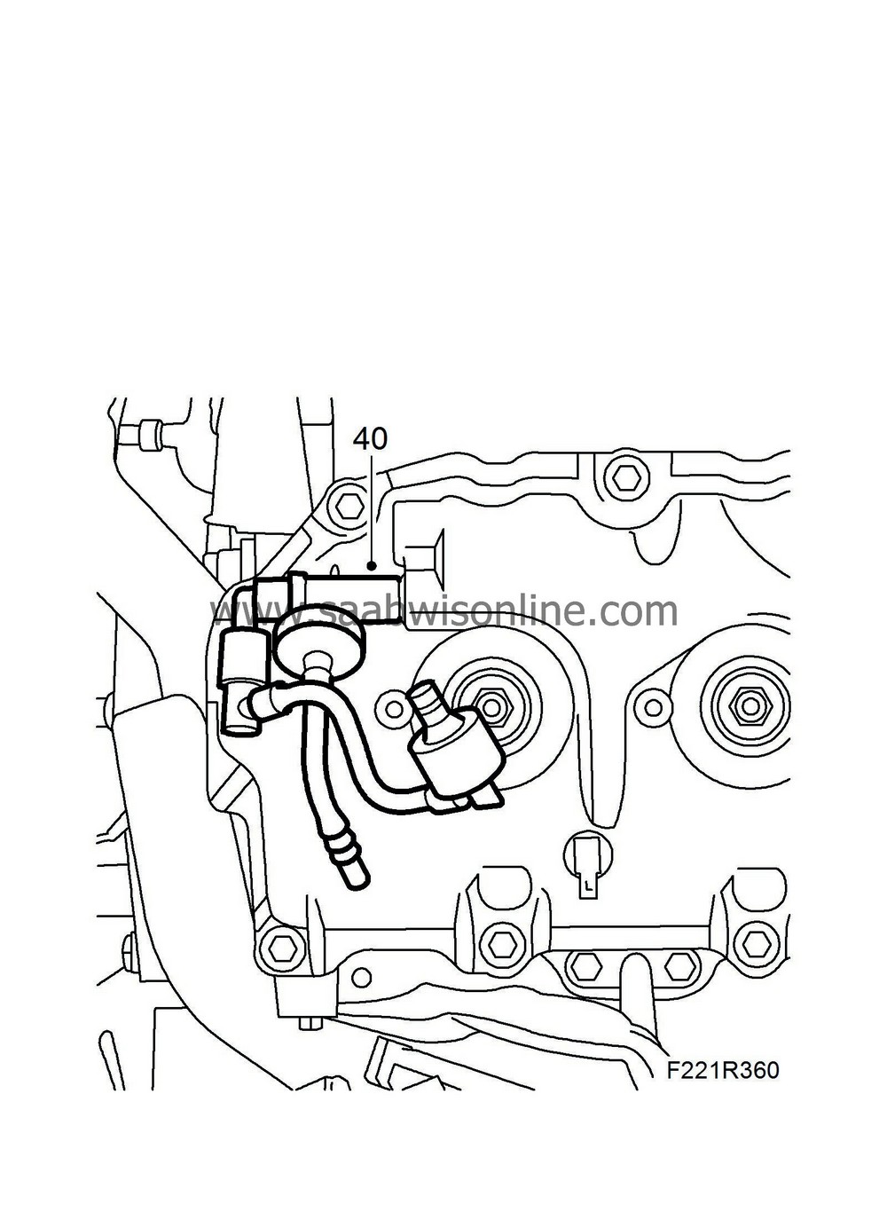
| 40. |
Remove the crankcase ventilation check valve from the camshaft cover for cylinders 1-3-5.
|
|
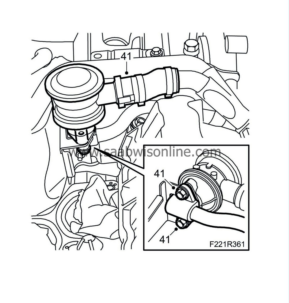
| 41. |
Undo the quick coupling and remove the secondary air system's valve for cylinders 2-4-6.
|
|
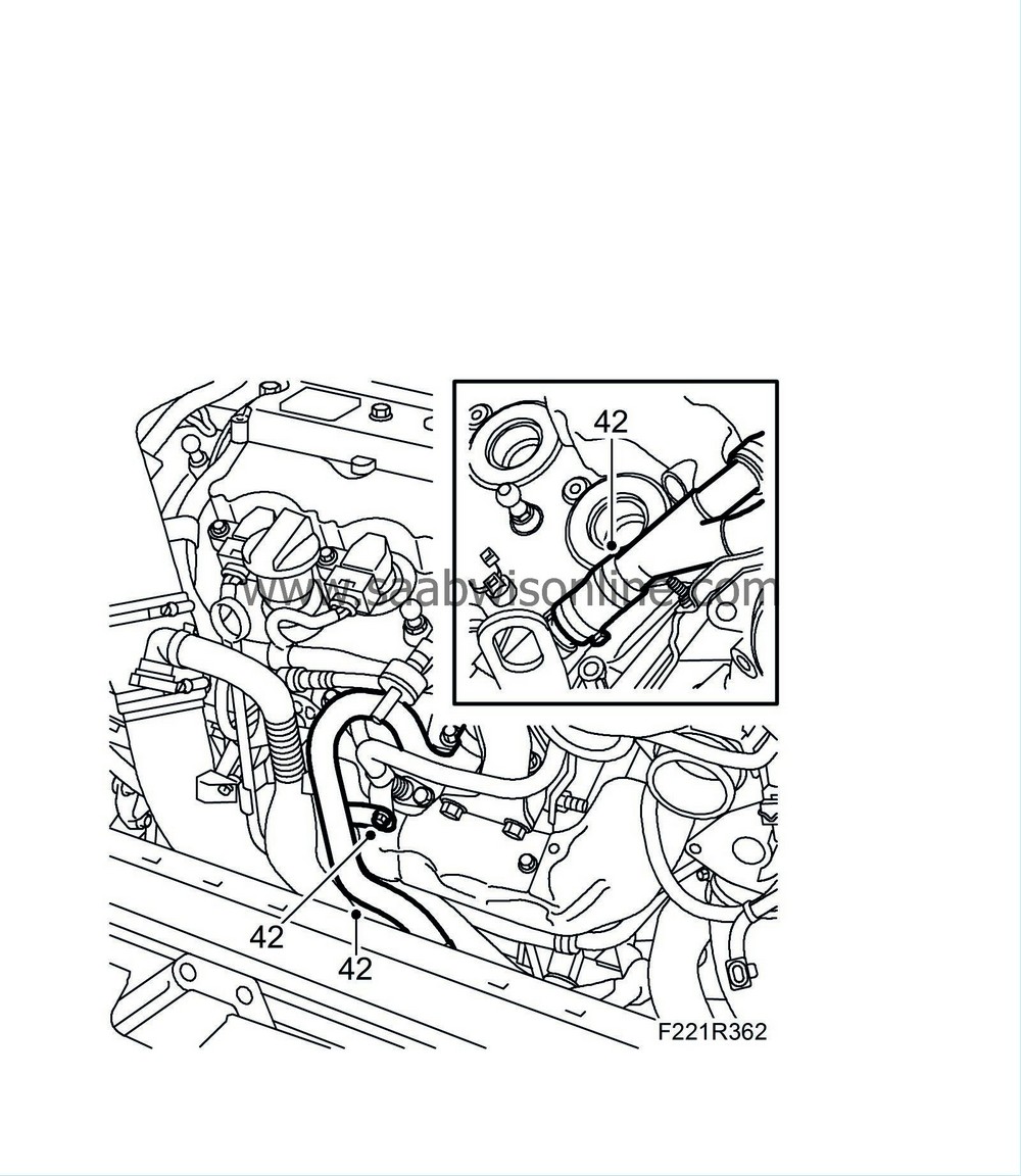
| 42. |
Undo the upper quick coupling by removing the bolt and removing the secondary air system's delivery line.
|
|
| 43. |
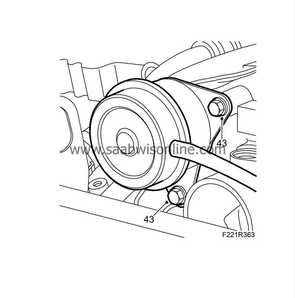
Remove the turbocharger diaphragm unit by undoing the bolt and pressing it out.
|
|
| 44. |
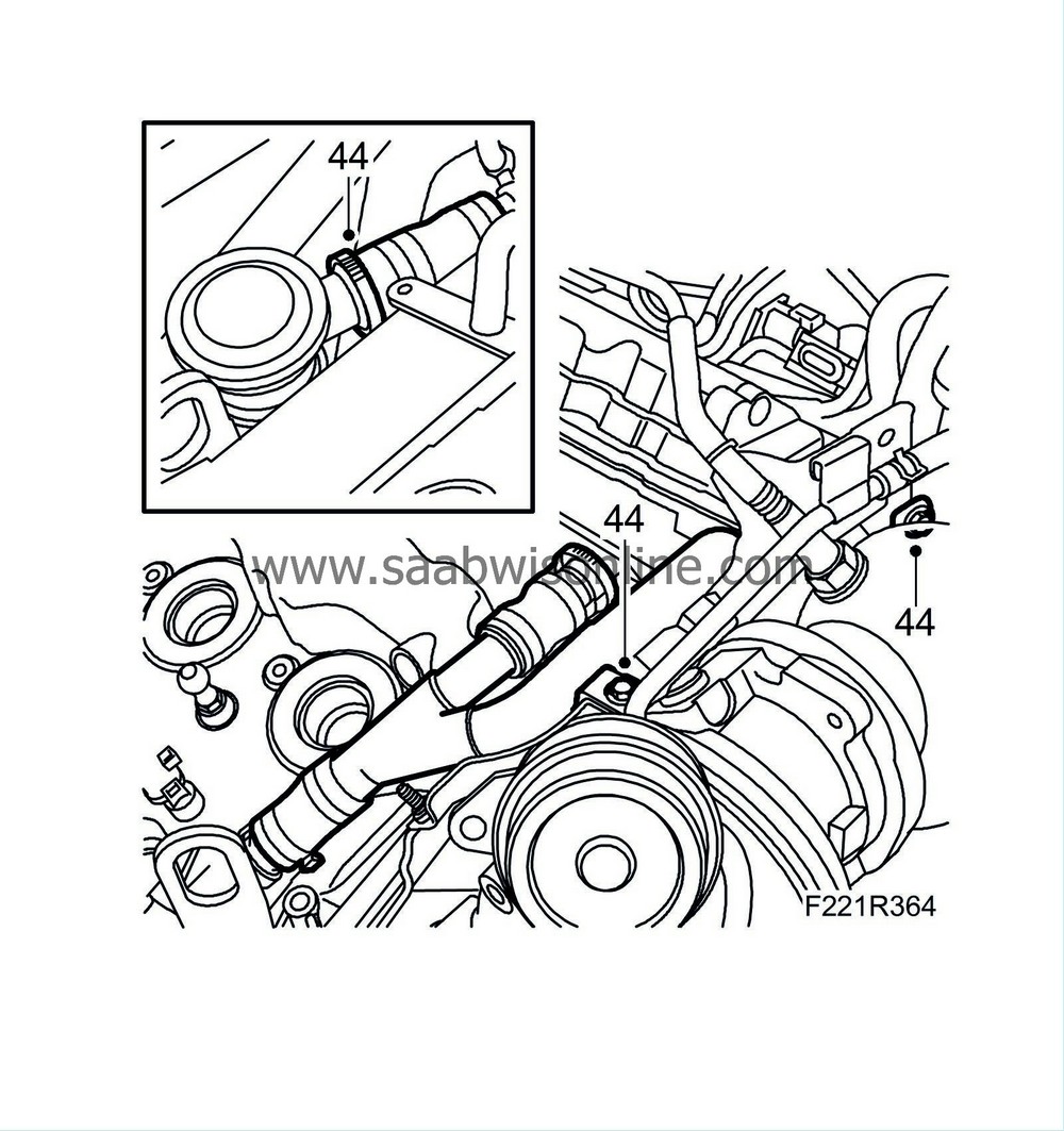
Remove the secondary air system's delivery line for cylinders 1-3-5.
|
|
| 45. |
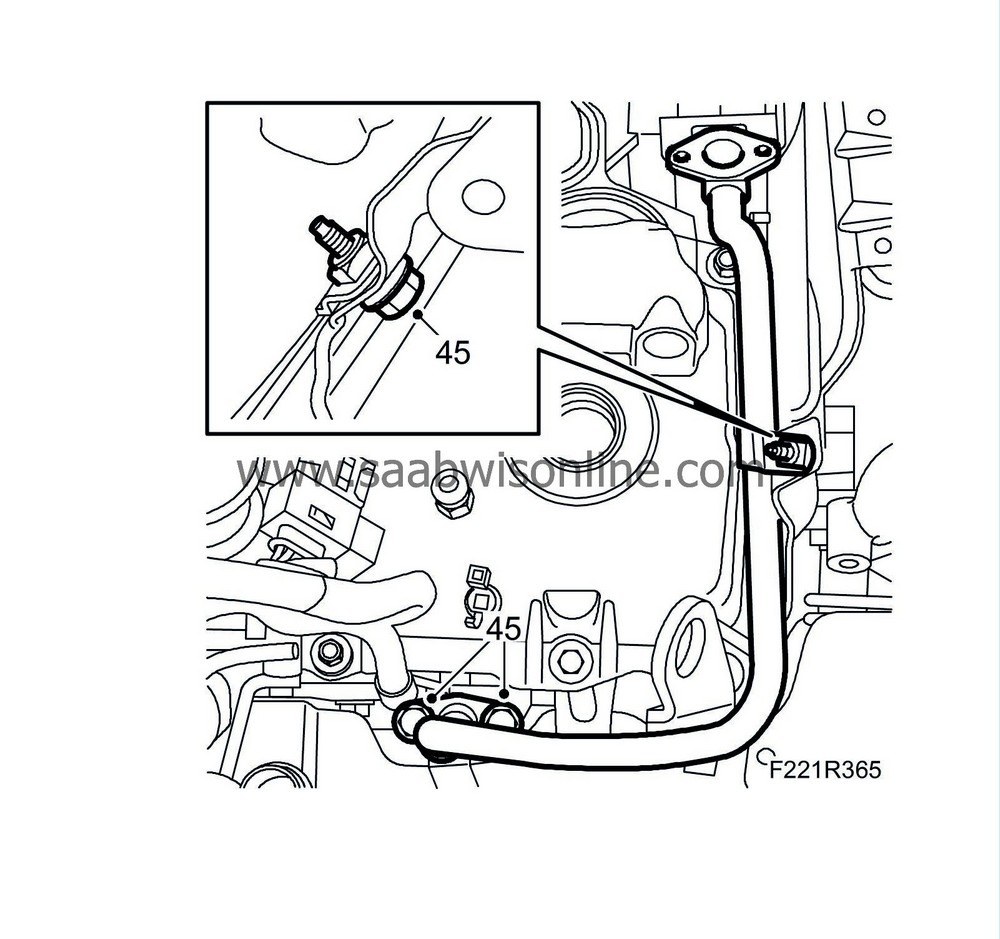
Remove the secondary air system's delivery line for cylinders 2-4-6.
|
|
| 46. |
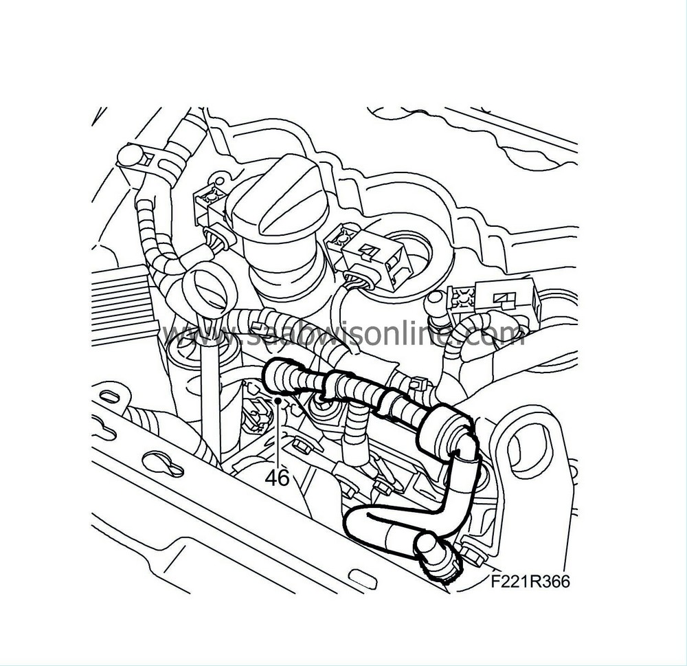
Remove the ventilation line to the oil dipstick's guide tube by undoing the quick coupling.
|
|
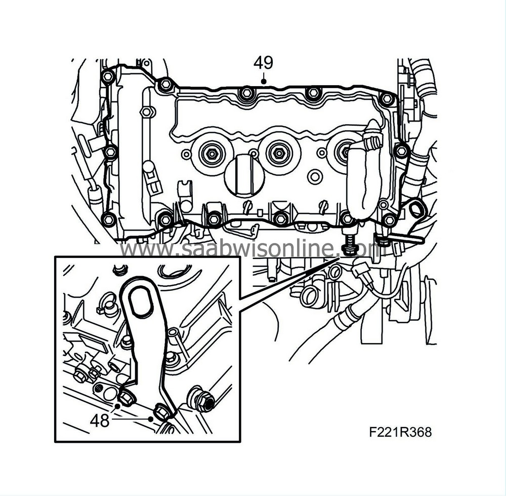
| 48. |
Remove the engine's transport lug by removing the bolts.
|
|
| 49. |
Remove the camshaft cover for cylinders 2-4-6 by removing the bolts.
|
|
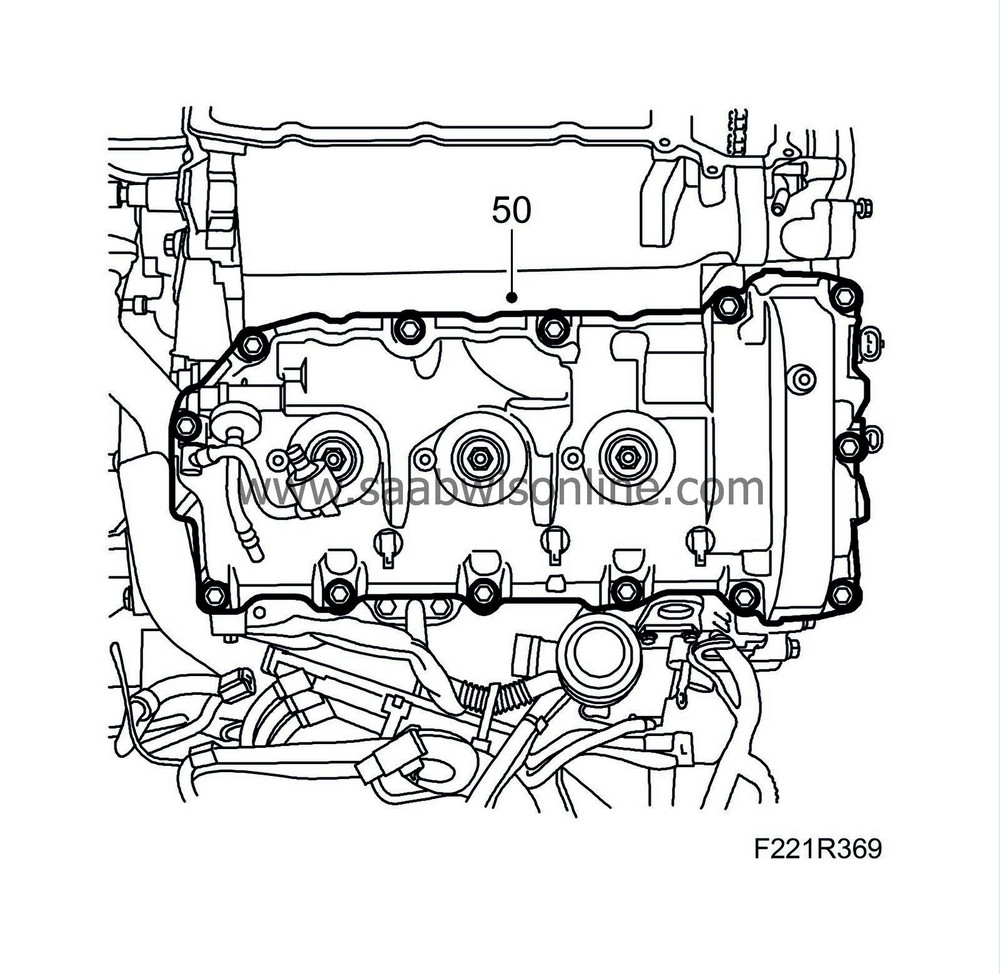
| 50. |
Remove the camshaft cover for cylinders 1-3-5 by removing the bolts.
|
|
| 51. |
Raise the car to half height.
|
|
| 52. |
Remove the front wheels.
|
|
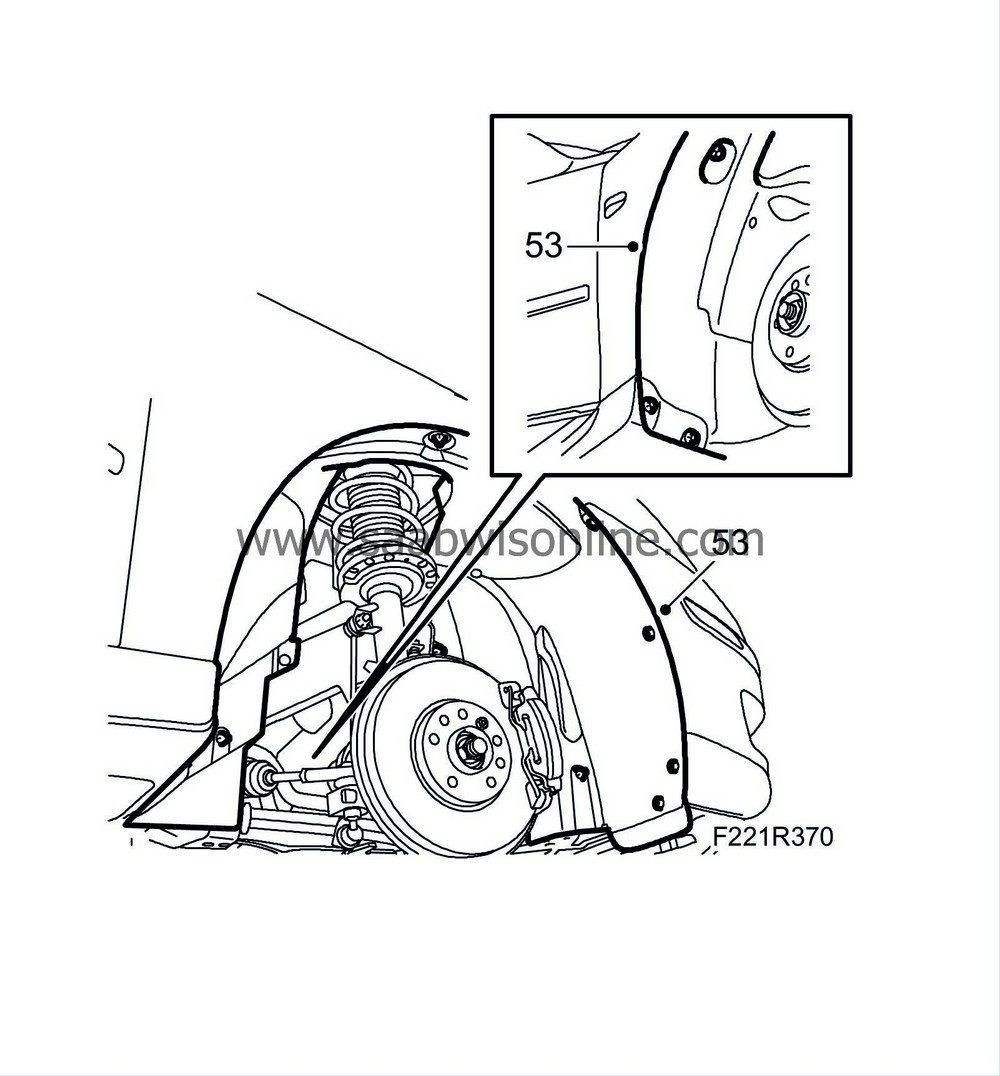
| 53. |
Remove the right wing liner.
|
|
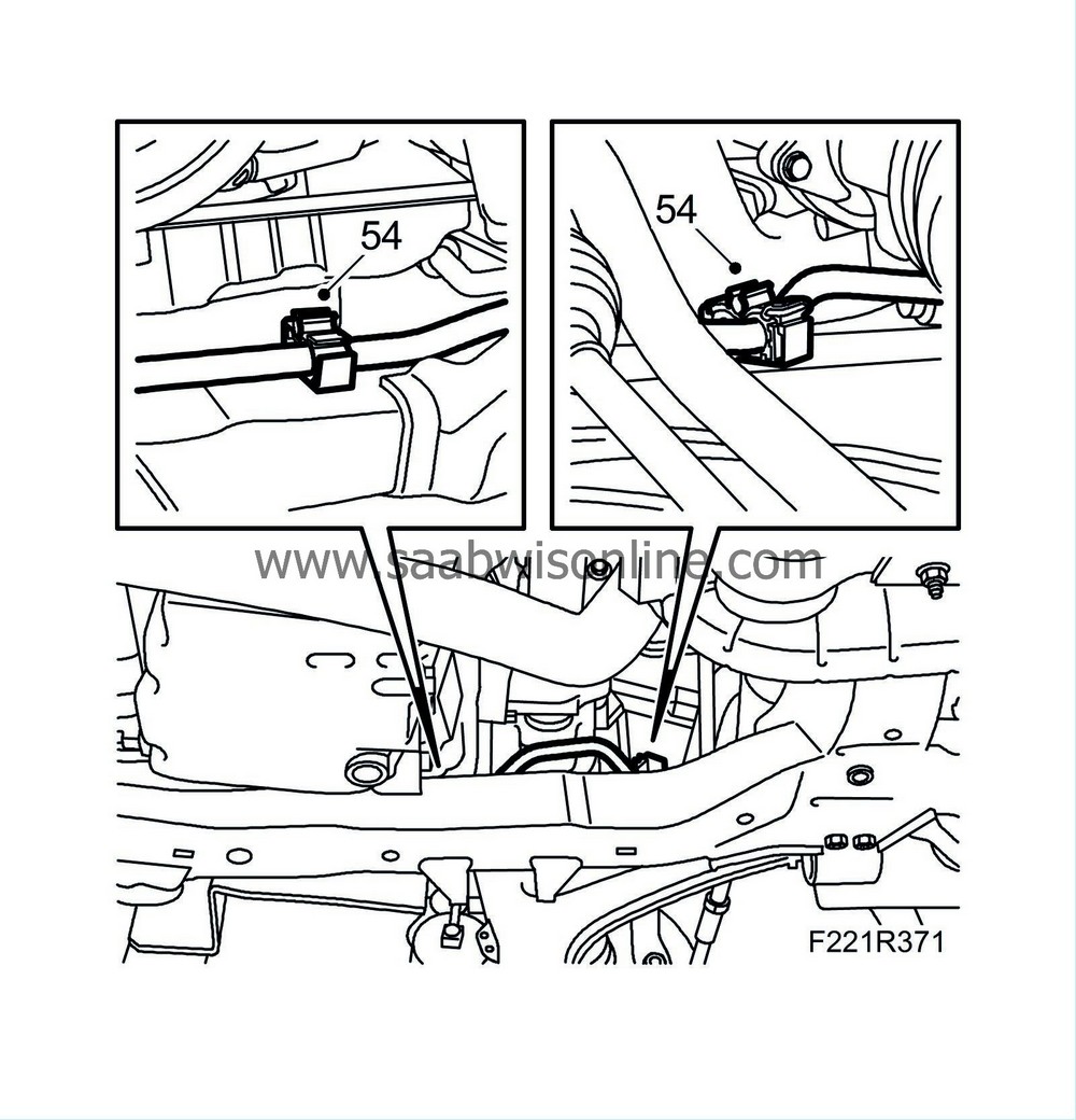
| 54. |
Remove the power steering hydraulic line from the holder on the front axle beam.
|
|
| 55. |
Remove
Engine mounting, right
.
|
|
| 56. |
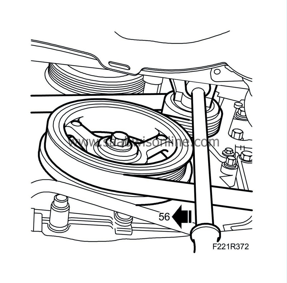
Relieve the load on the belt tensioner. Use a 1/4 " puller handle and remove the driver belt from the A/C compressor pulley.
|
|
| 57. |
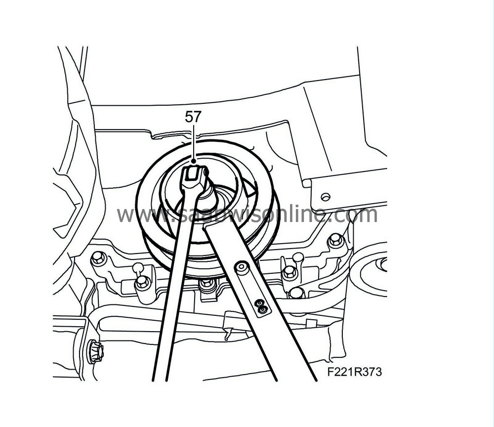
Remove the bolt holding the crankshaft pulley using
83 95 360 Holding tool, crankshaft pulley
(handle only) and
EN-47981 Holding tool, pulley
.
|
|||||||
| 58. |
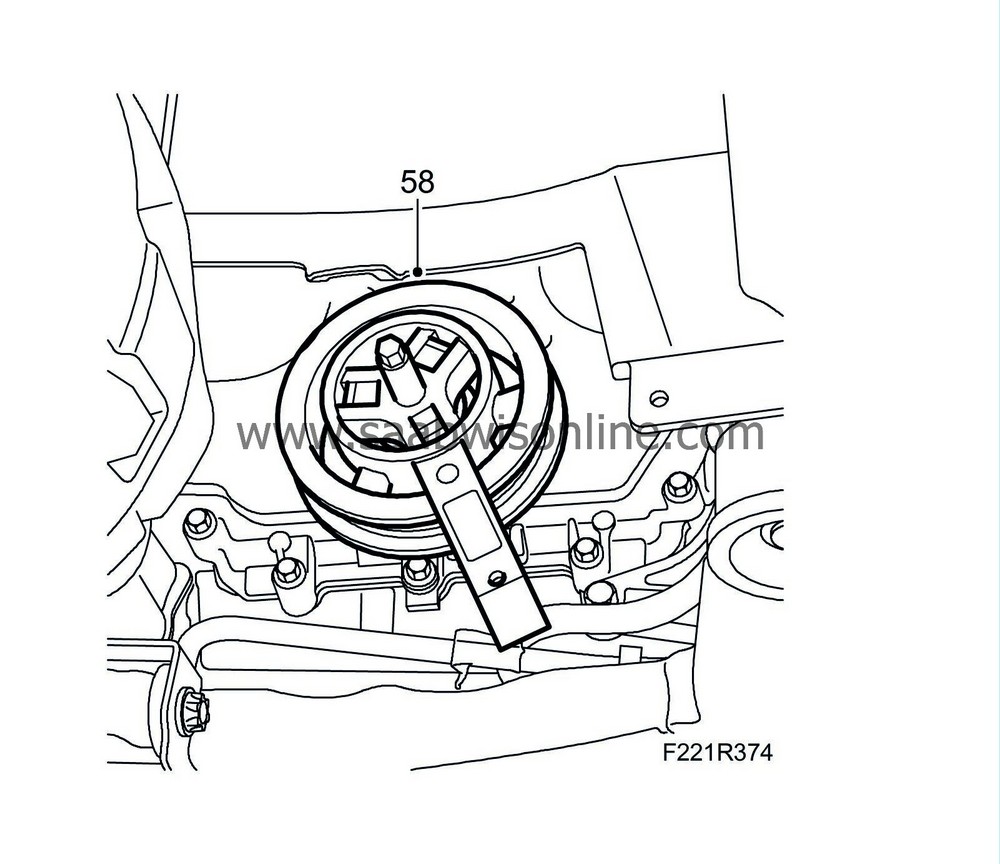
Remove the pulley using
EN-47982 Puller
and
EN-47981 Holding tool, pulley
.
|
|
| 59. |
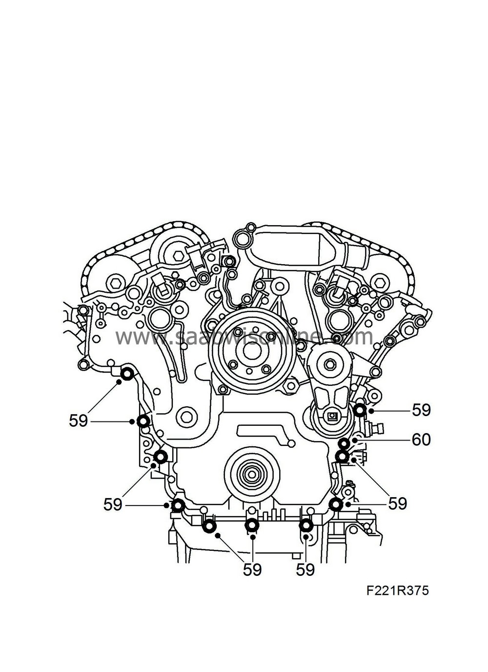
Remove the transmission housing at the bottom by removing the bolts.
|
|
| 60. |
Remove the wiring harness holder from the bottom of the transmission housing by removing the bolt.
|
|
| 61. |
Lower the car.
|
|
| 62. |
Remove the coolant line from the coolant outlet pipe by removing the bolt.
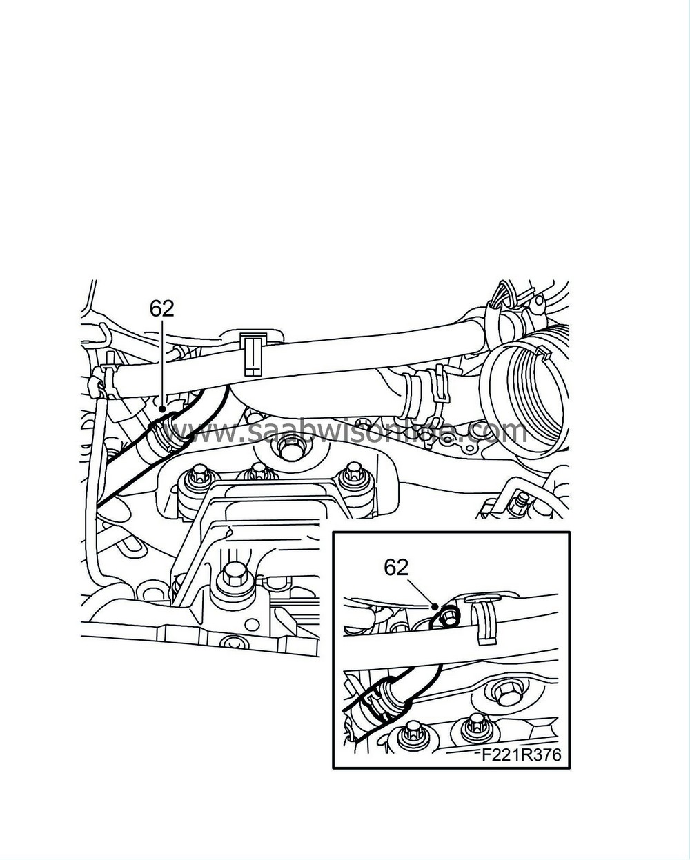
|
|
| 63. |
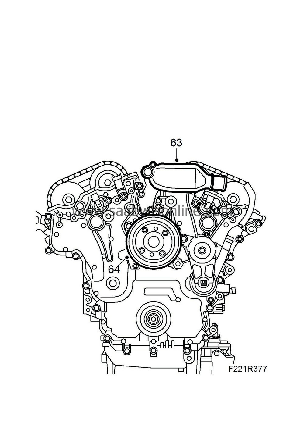
Remove the coolant outlet pipe by removing the coolant hose, remove the clamp and remove the bolts.
|
|
| 64. |
Remove the coolant pump pulley by removing the bolts. Hold firm with a screwdriver.
|
|
| 65. |
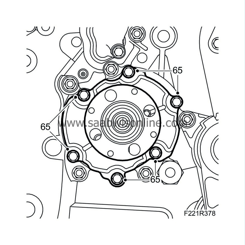
Remove the coolant pump by removing the bolts.
|
|
| 66. |
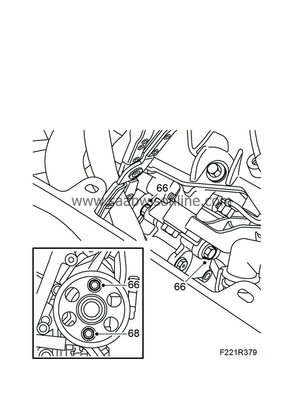
Remove the power steering pump at the top by removing the bolted joint.
|
|
| 67. |
Raise the car.
|
|
| 68. |
Remove the power steering pump at the bottom by removing the bolt. Move the power steering pump towards the front of the car
|
|
| 69. |
Lower the car.
|
|
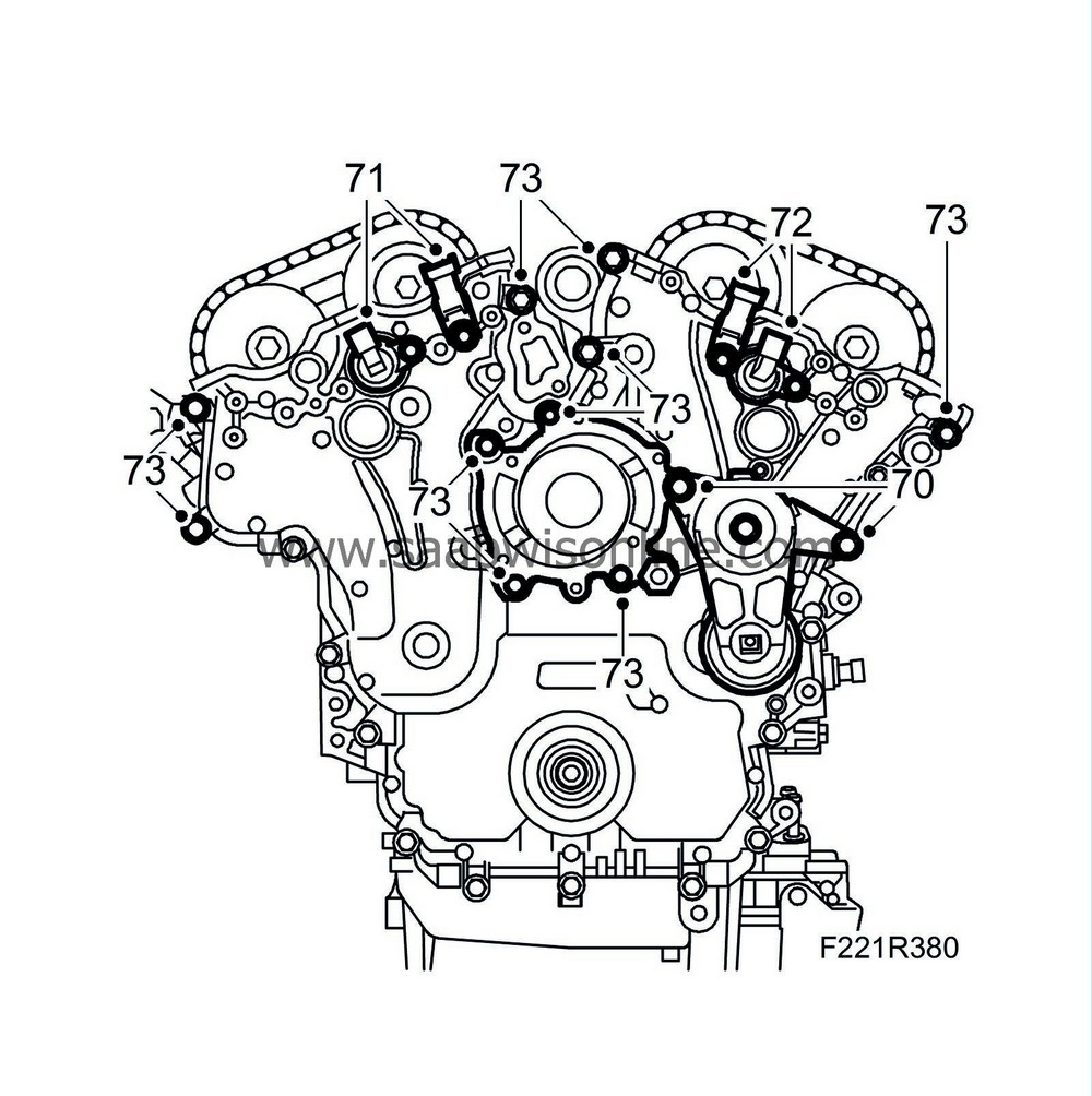
| 70. |
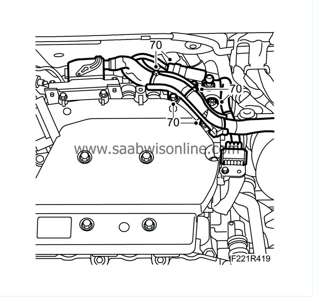
Remove the drive belt tensioner by removing the bolt.
|
|
| 71. |
Remove the camshaft setting valve for cylinders 1-3-5 by removing the bolt.
|
|
| 72. |
Remove the camshaft setting valve for cylinders 2-4-6 by removing the bolt.
|
|
| 73. |
Remove the upper bolts of the transmission housing.
|
|
| 74. |
Remove the timing cover. Carefully prize the cover loose with a pry bar and a screw that is carefully screwed in (to press the cover loose).
|
|
| 75. |
Remove the starter motor's wiring harness holder from the wiring harnesses.
|
|
| To fit |
| 1. |
Clean the sealing surfaces.
|
|
| 2. |
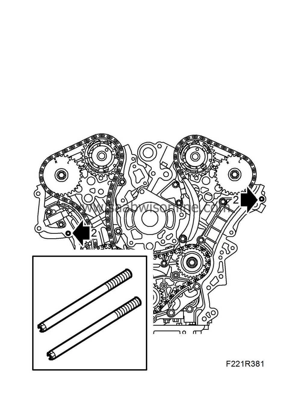
Fit
EN-46109-2 Centring tool
in the engine block and cylinder head.
|
|
| 3. |
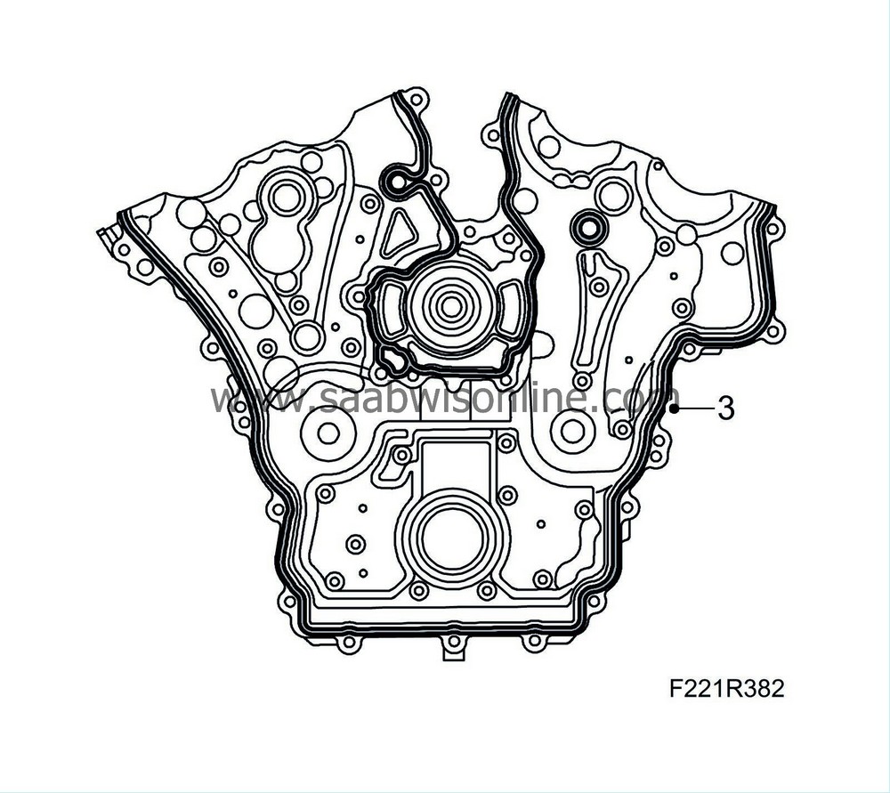
Apply
93 165 267 Flange sealant
. Apply an approx. 3 mm thick bead on the sealing surfaces of the transmission housing.
|
|
| 4. |
Install the transmission housing with help from an assistant. Check that the sealing bead remains undamaged during the alignment of the transmission housing.
|
|
| 5. |
Fit the upper bolts for the transmission housing. Remove the centring tools.
Tightening torque 23 Nm 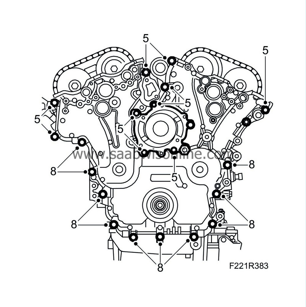
|
|
| 6. |
Secure the starter motor's wiring harness holder on the wiring harnesses.
|
|
| 7. |
Raise the car.
|
|
| 8. |
Fit the lower bolts of the transmission housing.
Tightening torque 23 Nm |
|
| 9. |
Fit the lower bolt to the power steering pump.
Tightening torque 22 Nm 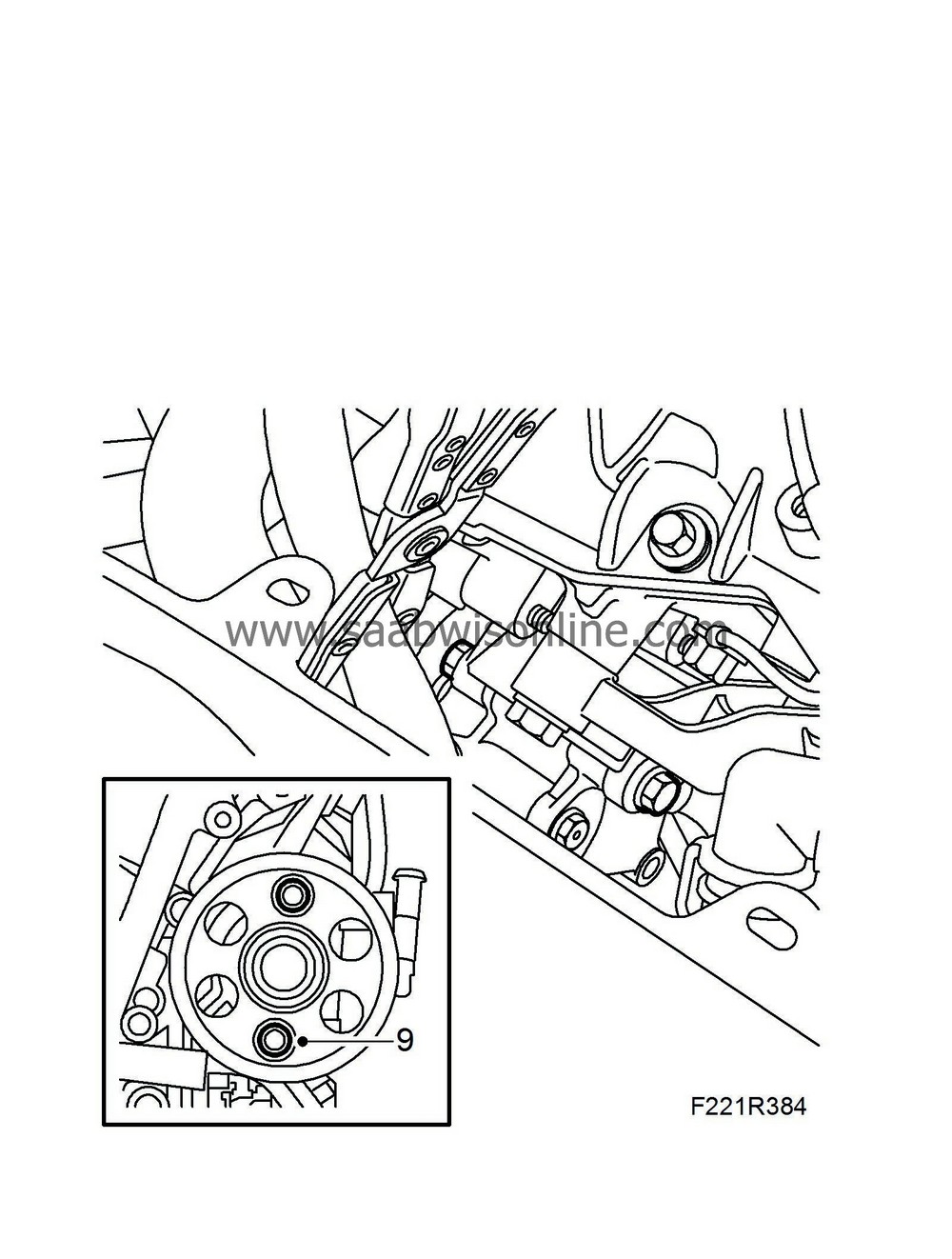
|
|
| 10. |
Fit the pulley to the crankshaft. Use
J-41998 Fitting tool
to press on the pulley.
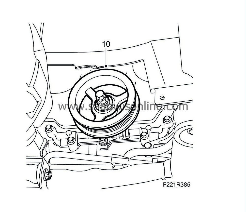
|
|
| 11. |
Fit the bolt using
83 95 360 Holding tool, crankshaft pulley
(handle only) and
EN-47981 Pulley holding tool
.
Tightening torque: 100 Nm + 150° (74 lbf ft + 150°) |
|
| 12. |
Secure the starter motor's wiring harness holder at the bottom. Tighten the bolt.
|
|
| 13. |
Lower the car.
|
|
| 14. |
Fit the camshaft setting solenoid valve for cylinders 2-4-6.
Tightening torque 10 Nm 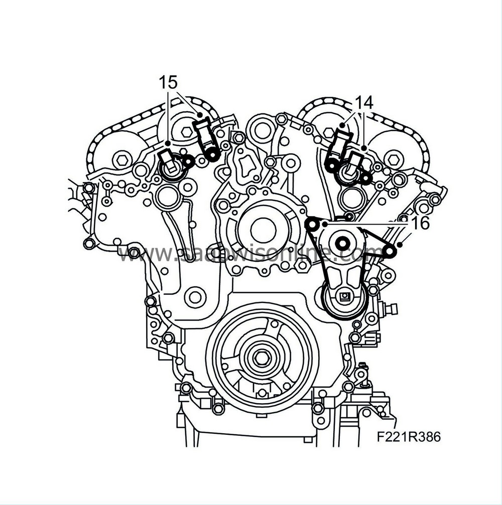
|
|
| 15. |
Fit the camshaft setting solenoid valve for cylinders 1-3-5.
Tightening torque 10 Nm |
|
| 16. |
Fit the belt tensioner and the bolt
Tightening torque 22 Nm |
|
| 17. |
Secure the starter motor's wiring harness holder at the top. Tighten the bolt.
|
|
| 18. |
Secure the power steering pump at the top.
Tightening torque 22 Nm 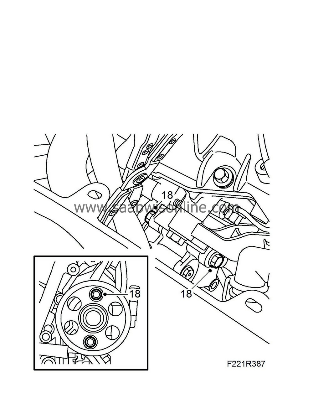
|
|
| 19. |
Fit the mounting bolts to the engine pad's attaching plate.
Tightening torque 44 Nm |
|
| 20. |
Fit the coolant pump. Use a new gasket.
Tightening torque 10 Nm 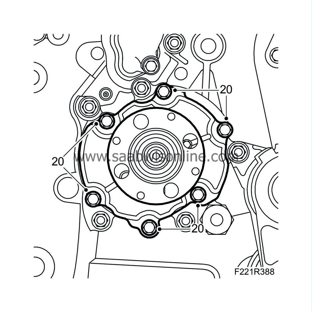
|
|
| 21. |
Fit the coolant pump's belt pulley. Counterhold with a screwdriver.
Tightening torque 12 Nm (9 lbf ft) 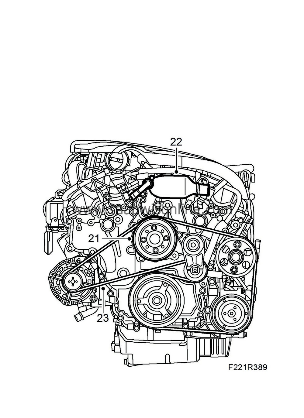
|
|
| 22. |
Fit the coolant outlet pipe. Use a new gasket.
Tightening torque, bolts: 12 Nm (9 lbf ft) Fit the coolant hose and secure the clamp. |
|
| 23. |
Unload the belt tensioner. Use a 1/4 " puller and fit the drive belt.
|
|
| 24. |
Fit
Engine mounting, right
.
|
|
| 25. |
Fit the holder to the power steering line.
Tightening torque, bolt 8 Nm (6 lbf ft) |
|
| 26. |
Fit the coolant line to the coolant outlet pipe. Use a new sealing ring.
Tightening torque 8 Nm (6 lbf ft) 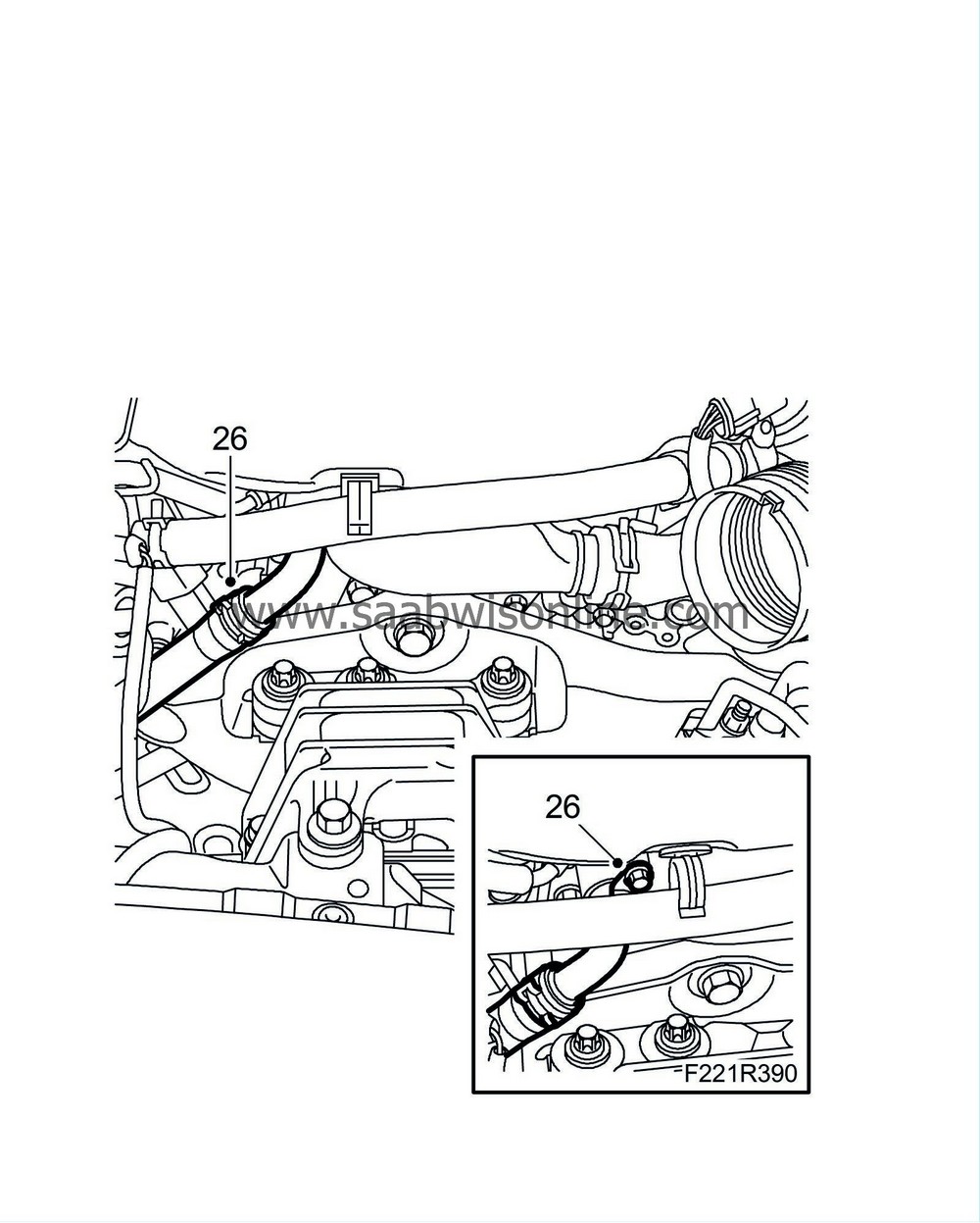
|
|
| 27. |
Raise the car.
|
|
| 28. |
Secure the power steering hydraulic line in the holder on the front axle beam.
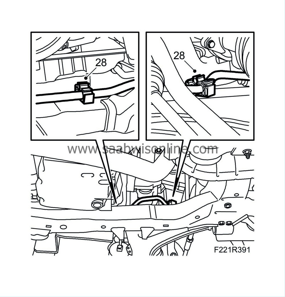
|
|
| 29. |
Lower the car to half height.
|
|
| 30. |
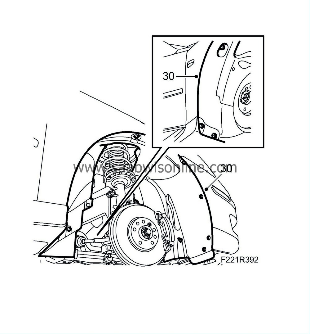
Fit the right-hand wing liner.
|
|
| 31. |
Fit the
Wheels
.
|
|
| 32. |
Clean the camshaft cover sealing surfaces.
|
|
| 33. |
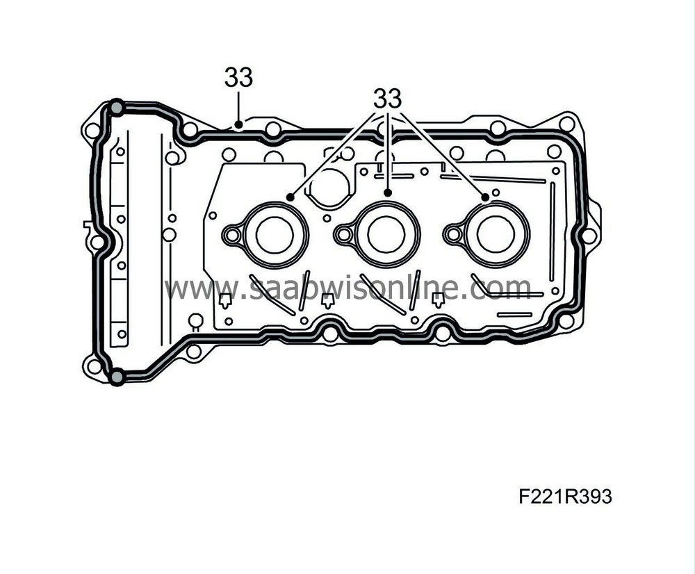
Replace the camshaft cover gasket for cylinders 2-4-6.
|
|
| 34. |
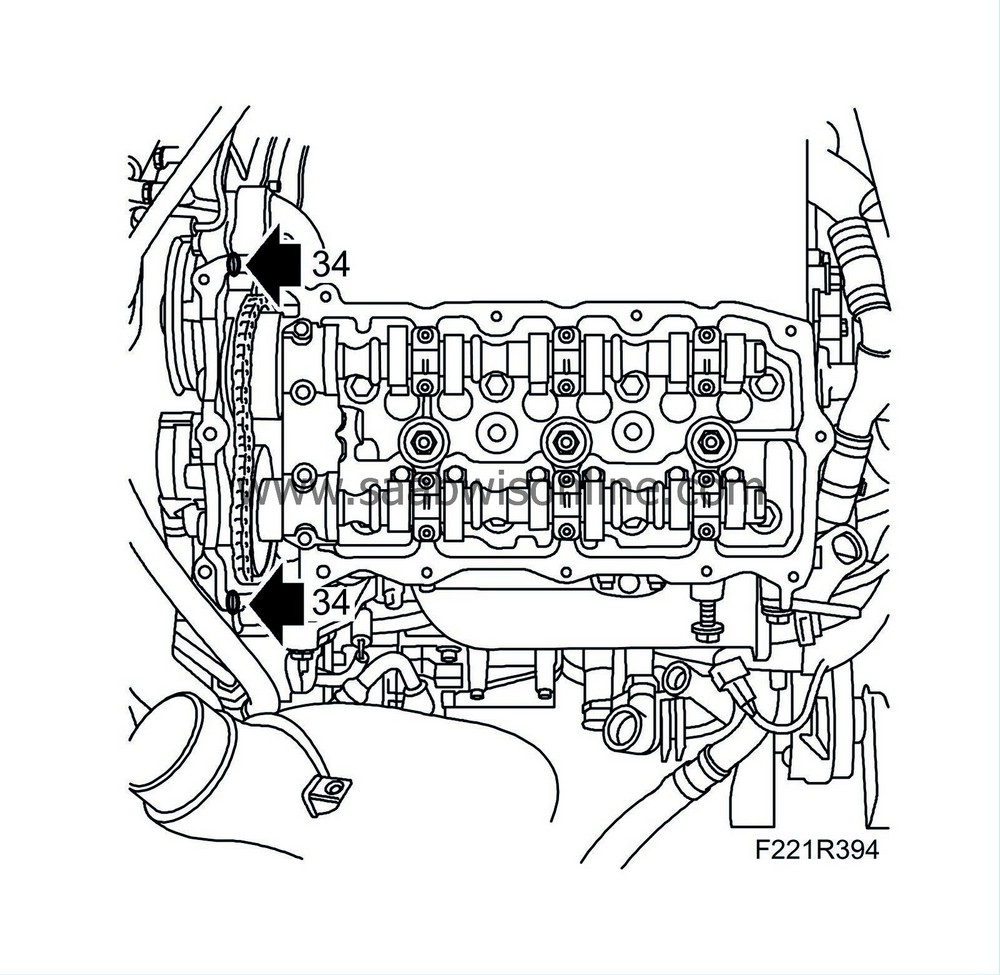
Apply an approx. 3 mm thick bead of sealing compound on the separating points of the cylinder head and transmission housing. Use
93 165 267 Flange sealant
.
|
|
| 35. |
Fit the camshaft cover for cylinders 2-4-6.
Tightening torque, bolts: 10 Nm (8 lbf ft) 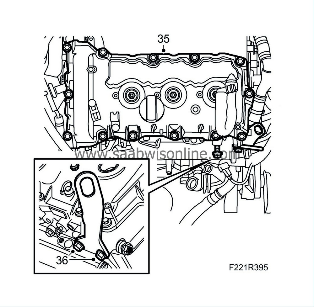
|
|
| 36. |
Fit the engine's transport lug.
Tightening torque, bolt 65 Nm (48 lbf ft) |
|
| 37. |
Clean the camshaft cover sealing surfaces.
|
|
| 38. |
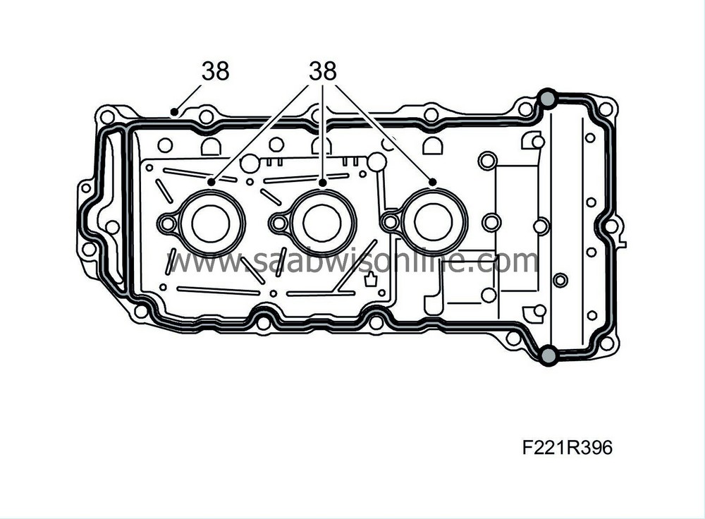
Replace the camshaft cover gasket for cylinders 1-3-5. Use new gaskets.
|
|
| 39. |
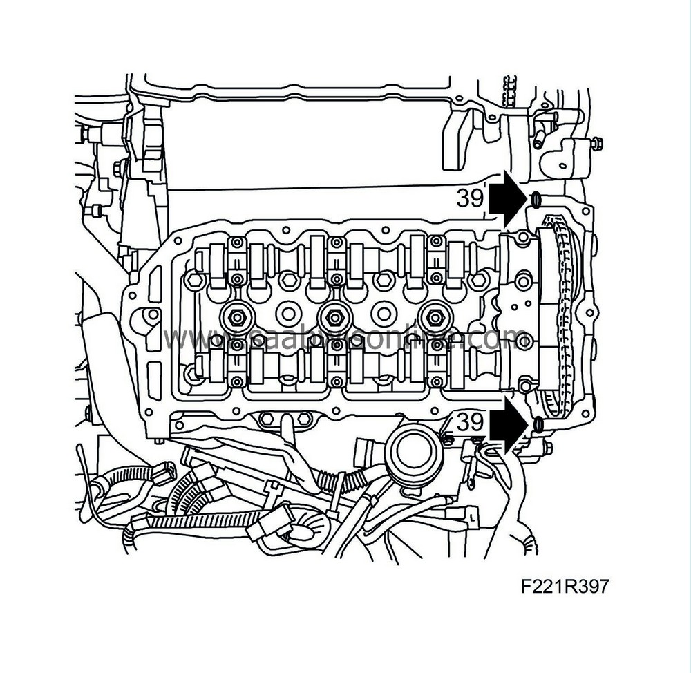
Apply an approx. 3 mm thick bead of sealing compound on the separating points of the cylinder head and transmission housing. Use
93 165 267 Flange sealant
.
|
|
| 40. |
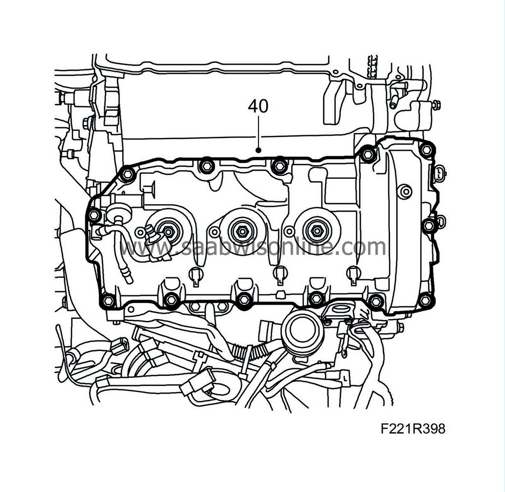
Fit the camshaft cover for cylinders 1-3-5.
Tightening torque, bolts: 10 Nm (8 lbf ft)
|
||||||||||
| 42. |
Fit the secondary air system line for cylinders 2-4-6. Fit the exhaust pipe.
Tightening torque, bolts: 10 Nm (8 lbf ft) 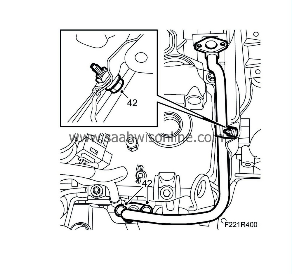
|
|
| 43. |
Fit the ventilation line to the oil dipstick's guide tube. Connect the quick coupling.
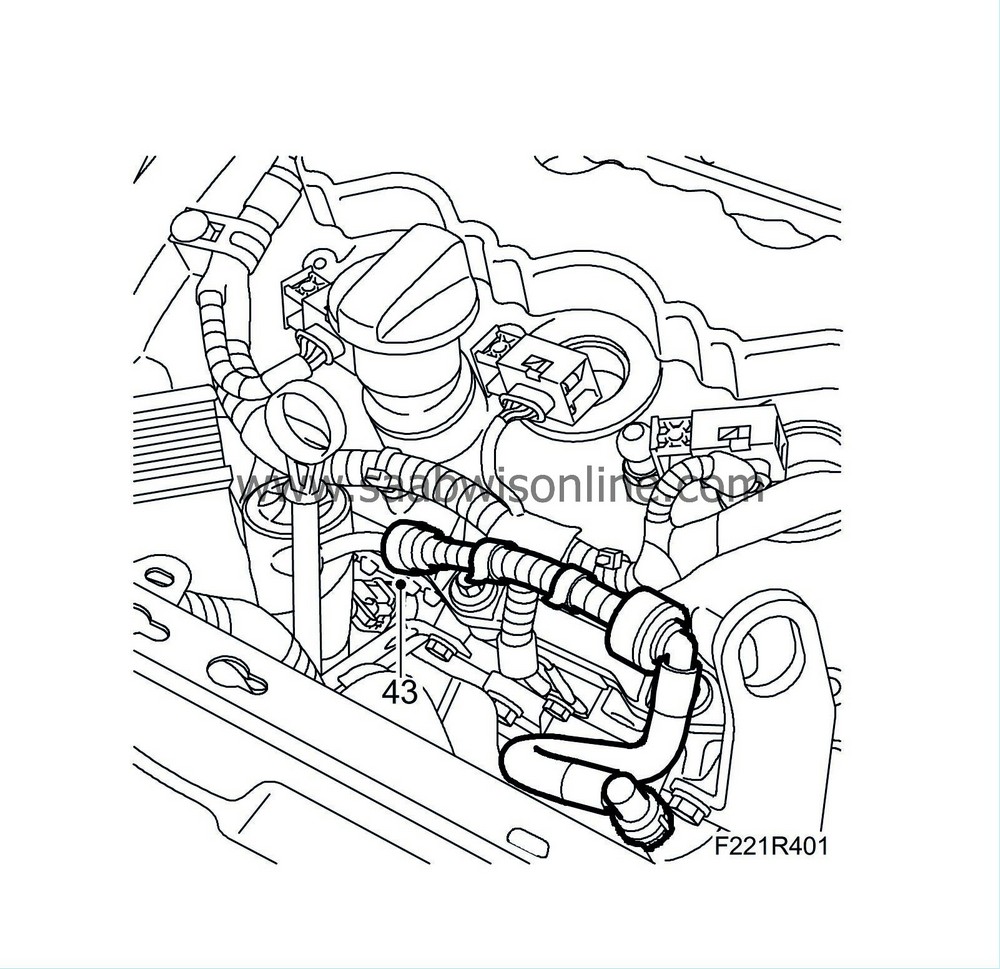
|
|
| 44. |
Fit the turbocharger diaphragm unit by fitting the bolts.
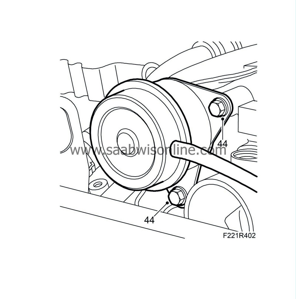
|
|
| 45. |
Fit the secondary air system's delivery line. Connect the quick couplings.
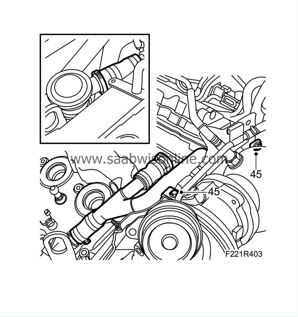
|
|
| 46. |
Fit the secondary air system's check valve for cylinders 2-4-6. Use a new gasket. Tighten the bolts and connect the quick coupling.
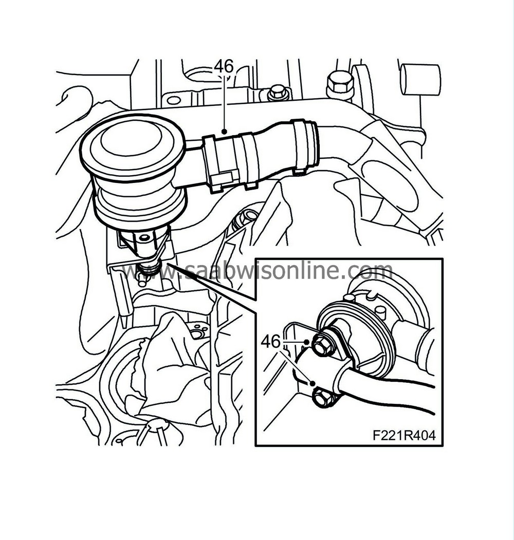
|
|
| 47. |
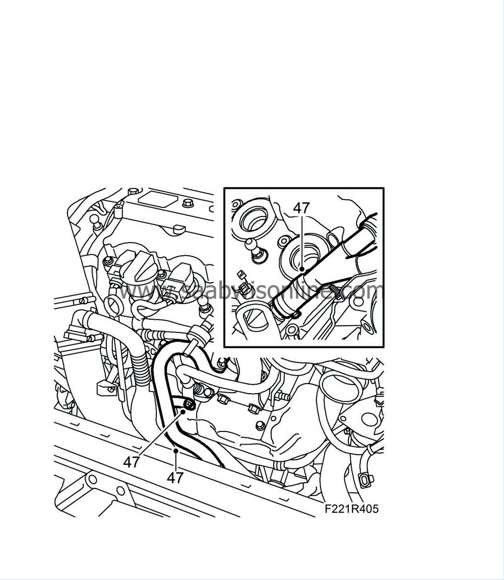
Fit the secondary air system's delivery line and bolt.
|
|
| 48. |
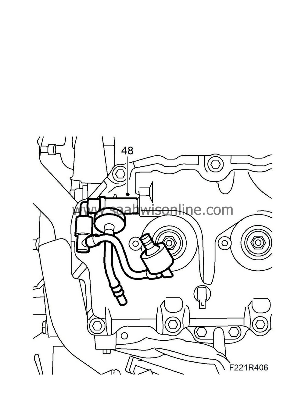
Fit the check valve to the crankcase ventilation on the camshaft cover for cylinders 1-3-5.
|
|
| 49. |
Fit the crankcase ventilation line on the turbocharger.
Tightening torque, bolt 10 Nm (8 lbf ft) 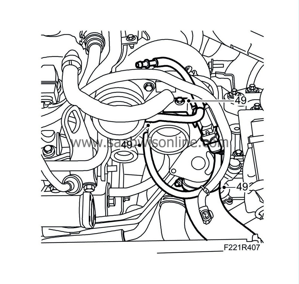
|
|
| 50. |
Fit the turbocharger's upper heat shield panel. Fit the nut.
Tightening torque, bolts: 10 Nm (8 lbf ft) 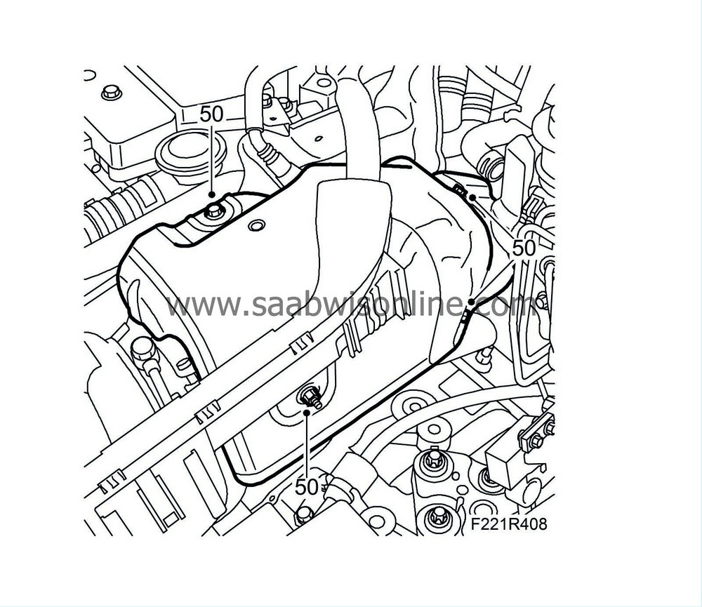
|
|
| 51. |
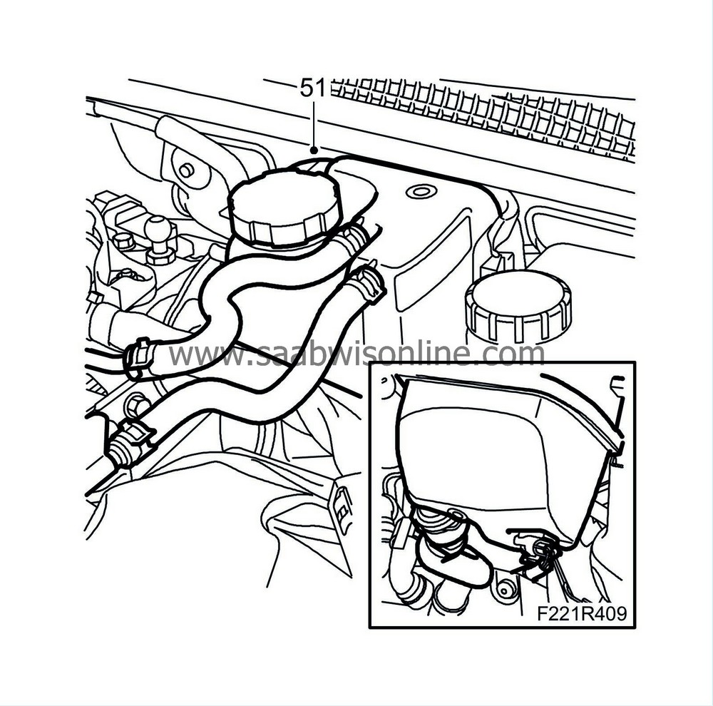
Fit the expansion tank in the holder.
|
|
| 52. |
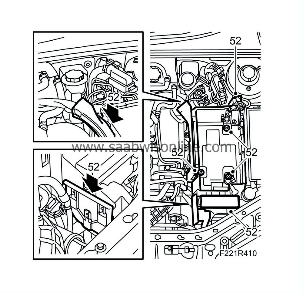
Fit
Battery cover, bottom section, B284
.
|
|
| 53. |
Fit the charge pressure regulator's wiring harness. Plug in the connector. Fit the cable tie.
|
|
| 54. |
Fit the ignition coils for cylinders 2-4-6. Plug in the connectors.
Tightening torque, bolts: 10 Nm (8 lbf ft) 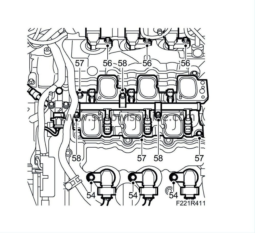
|
|
| 55. |
Fit the wiring harness holder on the camshaft cover for cylinders 1-3-5. Secure in the holder.
|
|
| 56. |
Fit the ignition coils for cylinders 1-3-5. Plug in the connectors and fit the bolts.
Tightening torque, bolts: 10 Nm (8 lbf ft) |
|
| 57. |
Fit the lower section of the intake manifold with a new seal.
Remove the rags from the inlet ducts. Tightening torque, bolts: 23 Nm (17 lbf ft) |
|
| 58. |
Fit the fuel rail with injectors.
Tightening torque, bolts: 10 Nm (8 lbf ft) |
|
| 59. |
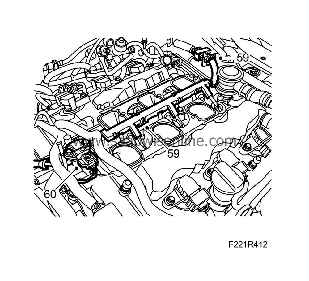
Fit the injectors' wiring harness. Plug in the connectors.
|
|
| 60. |
Plug in the connectors to the fuel pressure sensor.
|
|
| 61. |
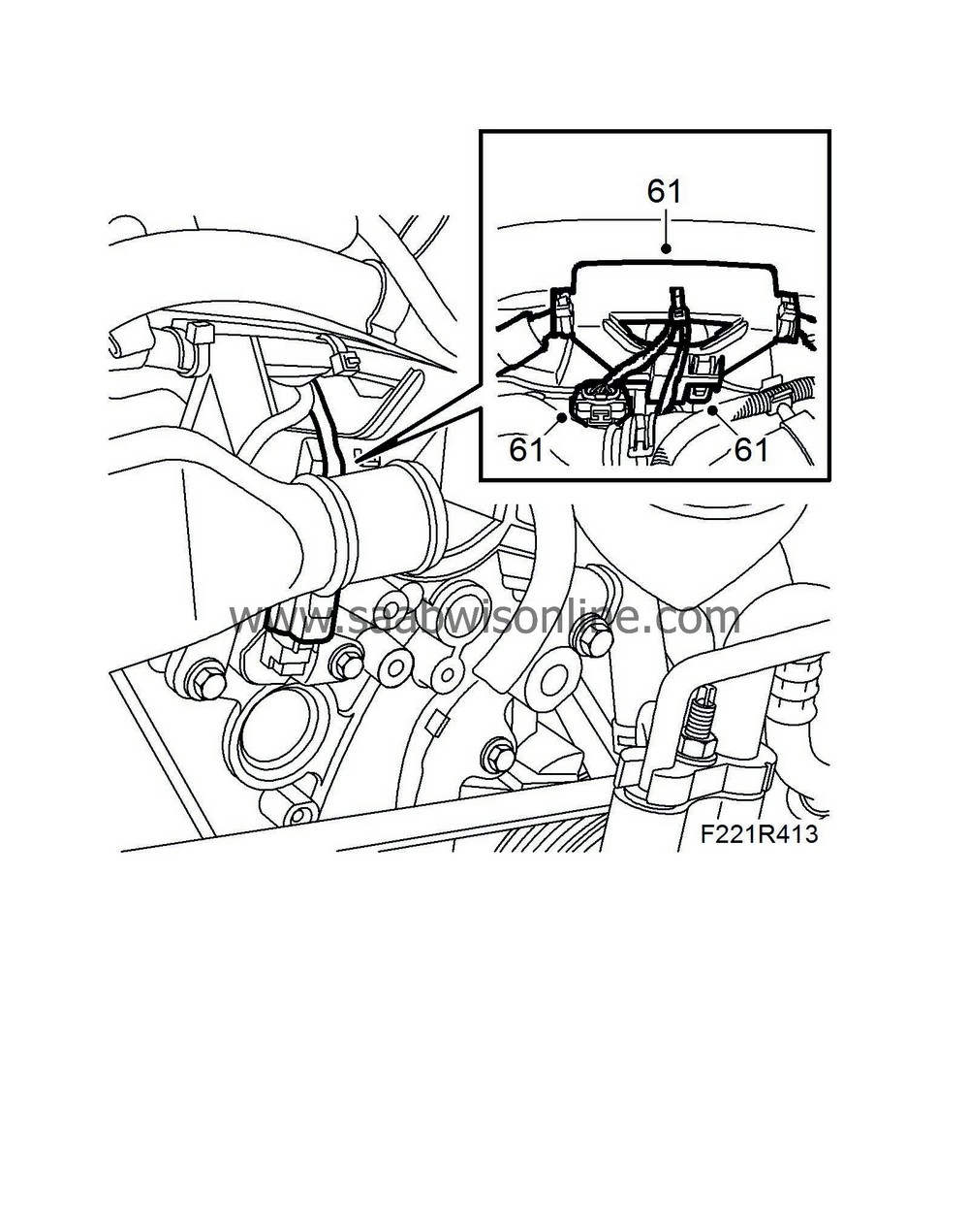
Fit the wiring harness to the camshaft guide for cylinders 2-4-6. Plug in the connectors and secure in the holder.
|
|
| 62. |
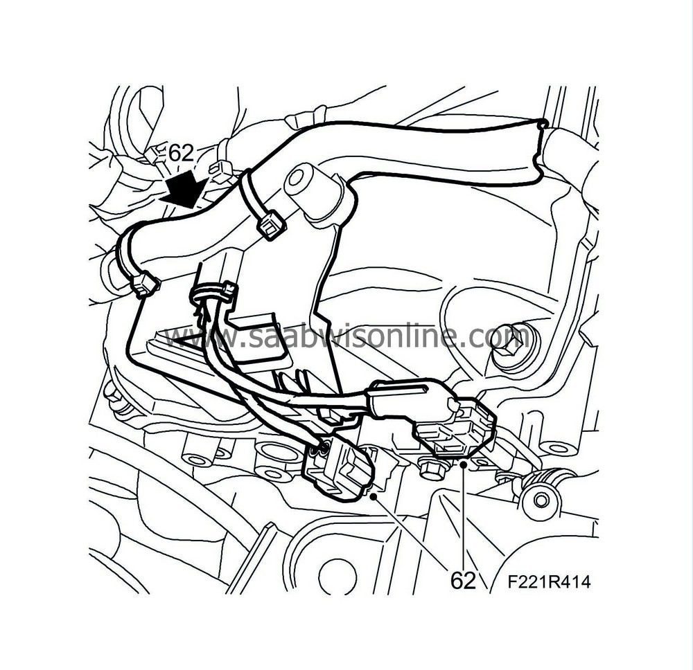
Connect the wiring harness to the camshaft guide for cylinders 1-3-5. Plug in the connectors and secure in the holder.
|
|
| 63. |
Fit the power steering reservoir. Fit the return hose. Secure the clamp.
Tightening torque, bolt 9 Nm (7 lbf ft). 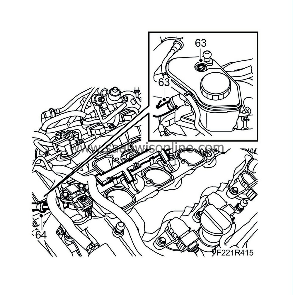
|
|
| 64. |
Connect the fuel delivery line.
|
|
| 65. |
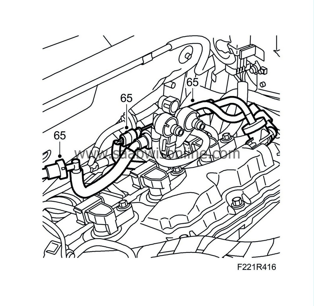
Fit the bleeder valve plus lines. Connect the quick couplings. Plug in the connectors to the bleeder valve.
|
|
| 66. |
Fit the upper section of the intake manifold. Plug in the throttle body's connector. Use new gaskets.
Tightening torque, bolts: 23 Nm (17 lbf ft) 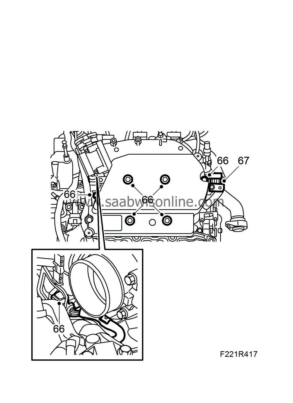
|
|
| 67. |
Fit the holder to the injector's connector.
Tightening torque, bolt 10 Nm (8 lbf ft) |
|
| 68. |
Fit the lines for the crankcase ventilation.
Tightening torque, bolt 10 Nm (8 lbf ft) 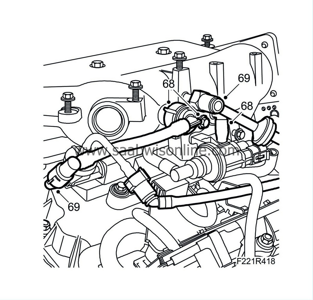
|
|
| 69. |
Fit the vacuum line on the upper section of the intake manifold. Connect the quick coupling.
|
|
| 71. |
Fit the engine control module. Fit the bolts.
Tightening torque, bolts: 10 Nm (8 lbf ft) 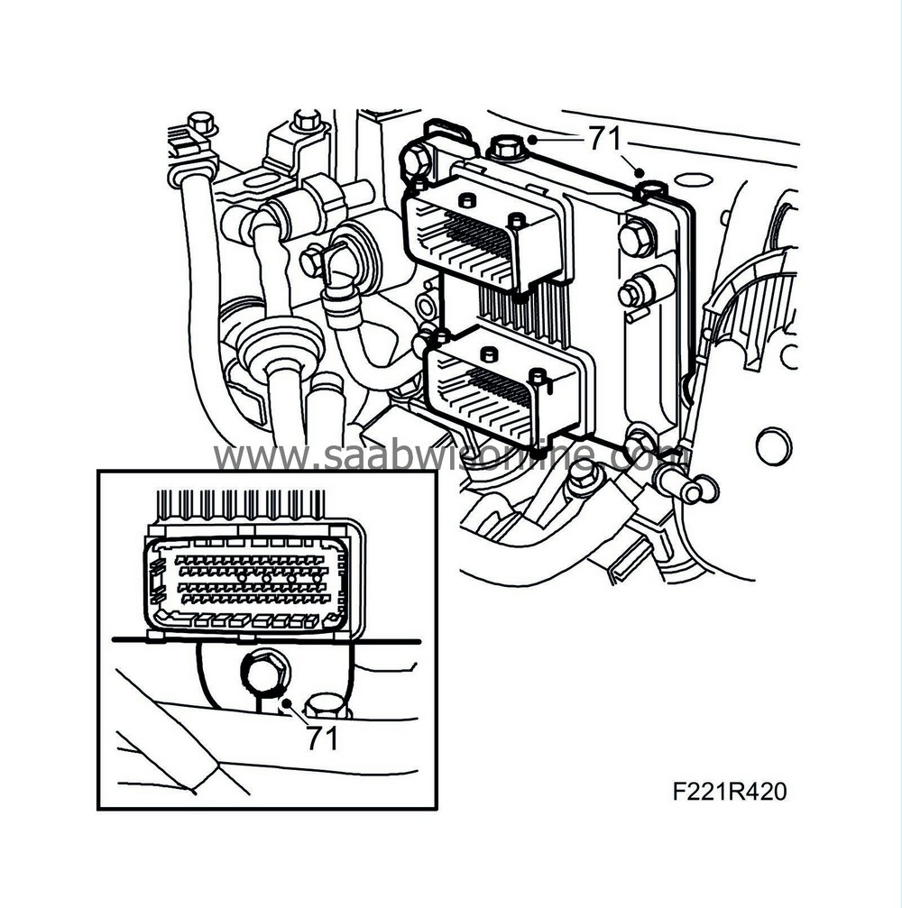
|
|
| 72. |
Fit the ground connection.
Plug in the engine control module connector. 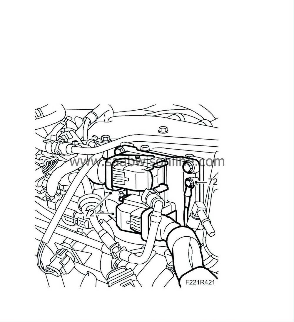
|
|
| 73. |
Fit the coolant return line. Fit the clamps.
Tightening torque, bolts: 10 Nm (8 lbf ft) 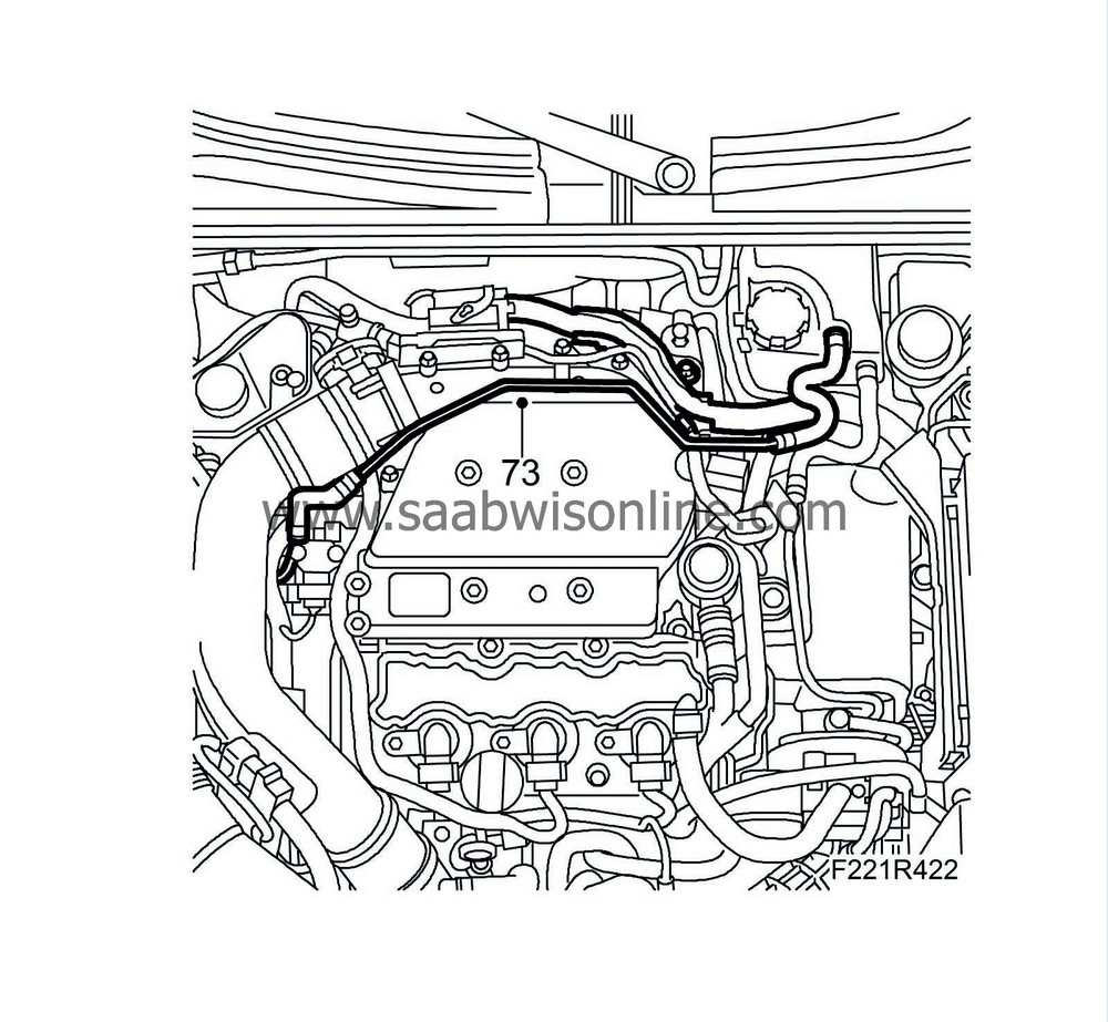
|
|
| 74. |
Fit the charge air pipe. Fit the clamp.
Tightening torque, clamp 3.5 Nm Plug in the charge pressure sensor connector. Secure the power steering line with clips. 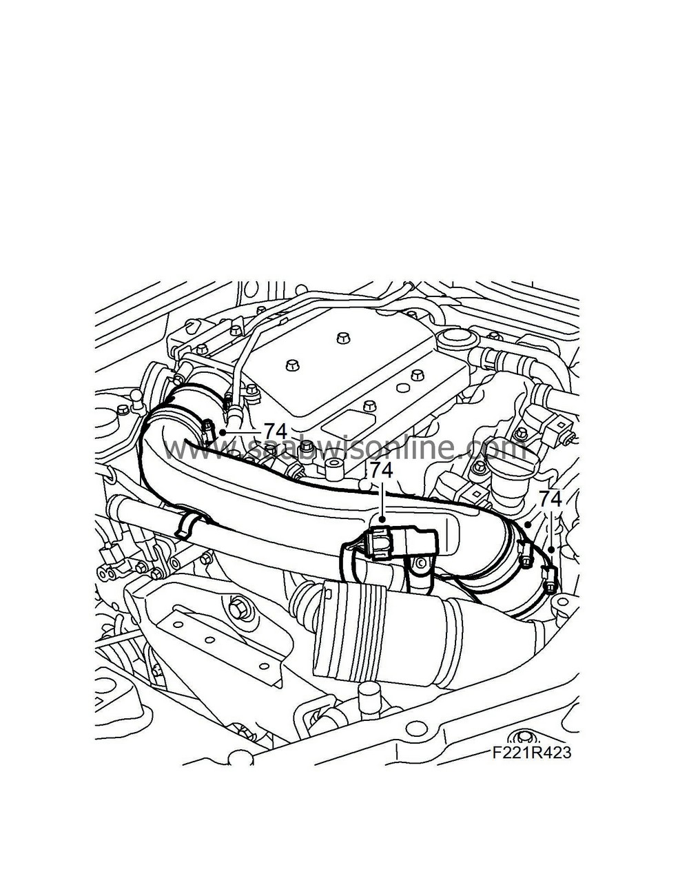
|
|
| 75. |
Fit the air intake pipe.
Tightening torque, clamp: 3.5 Nm (2.5 lbf ft) Tightening torque, bolt 1.5 Nm (1.1 lbf ft). 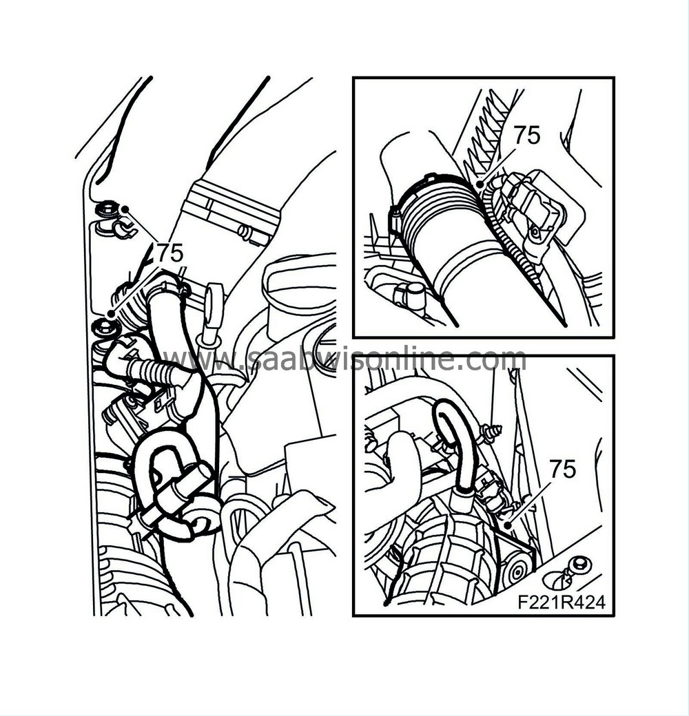
|
|
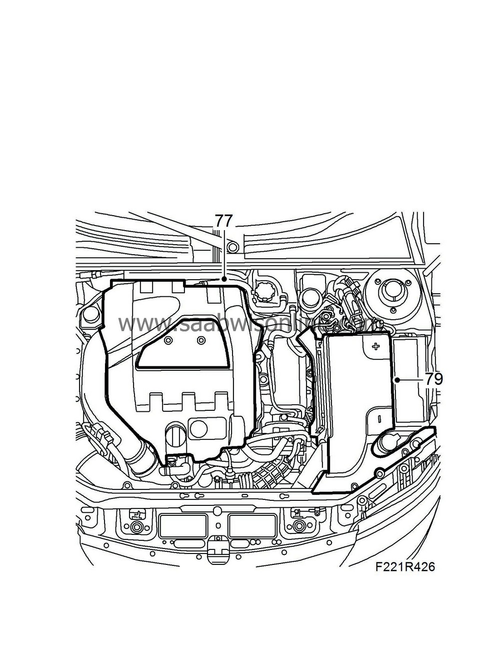
| 77. |
Fit the upper engine cover. Remove the oil filler opening's screw cap. Fit the protective cover. Fit the oil filler opening's screw cap.
|
|
| 78. |
Fill and bleed the cooling system, see
Bleeding and charging the cooling system
.
|
|
| 79. |
Connect the negative cable and fit the battery cover.
Tightening torque, clamps 3.5 Nm (2.5 lbf ft) |
|
| 80. |
Close the bonnet.
|
|

 Warning
