PRE-RELEASE
Intermediate exhaust pipe, front, B284
| Intermediate exhaust pipe, front, B284 |
| To remove |
|
|||||||
| Important | ||
|
Always use wing covers when working in the engine bay. |
||
| 1. |
Remove the battery cover and the engine cover.
|
|
| 2. |
Remove the battery cable.
|
|
| 3. |
Remove the battery.
|
|
| 4. |
Remove
Battery cover, bottom, B284
.
|
|
| 5. |
Remove
Upper radiator member, B284
.
|
|
| 6. |
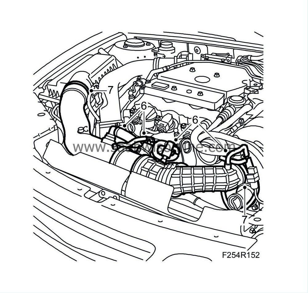
Unplug the mass air flow sensor connector. Detach the secondary air pipe, the delivery hose from the turbocharger intake manifold and the crankcase ventilation pipes.
|
|
| 7. |
Detach the turbocharger intake manifold from the air cleaner casing cover and the turbocharger.
|
|
| 8. |
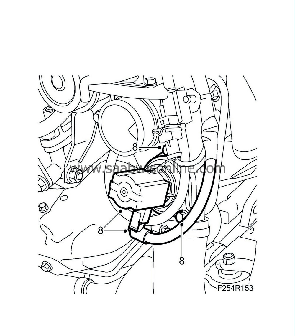
Remove the bypass valve and unplug the connector.
|
|
| 9. |
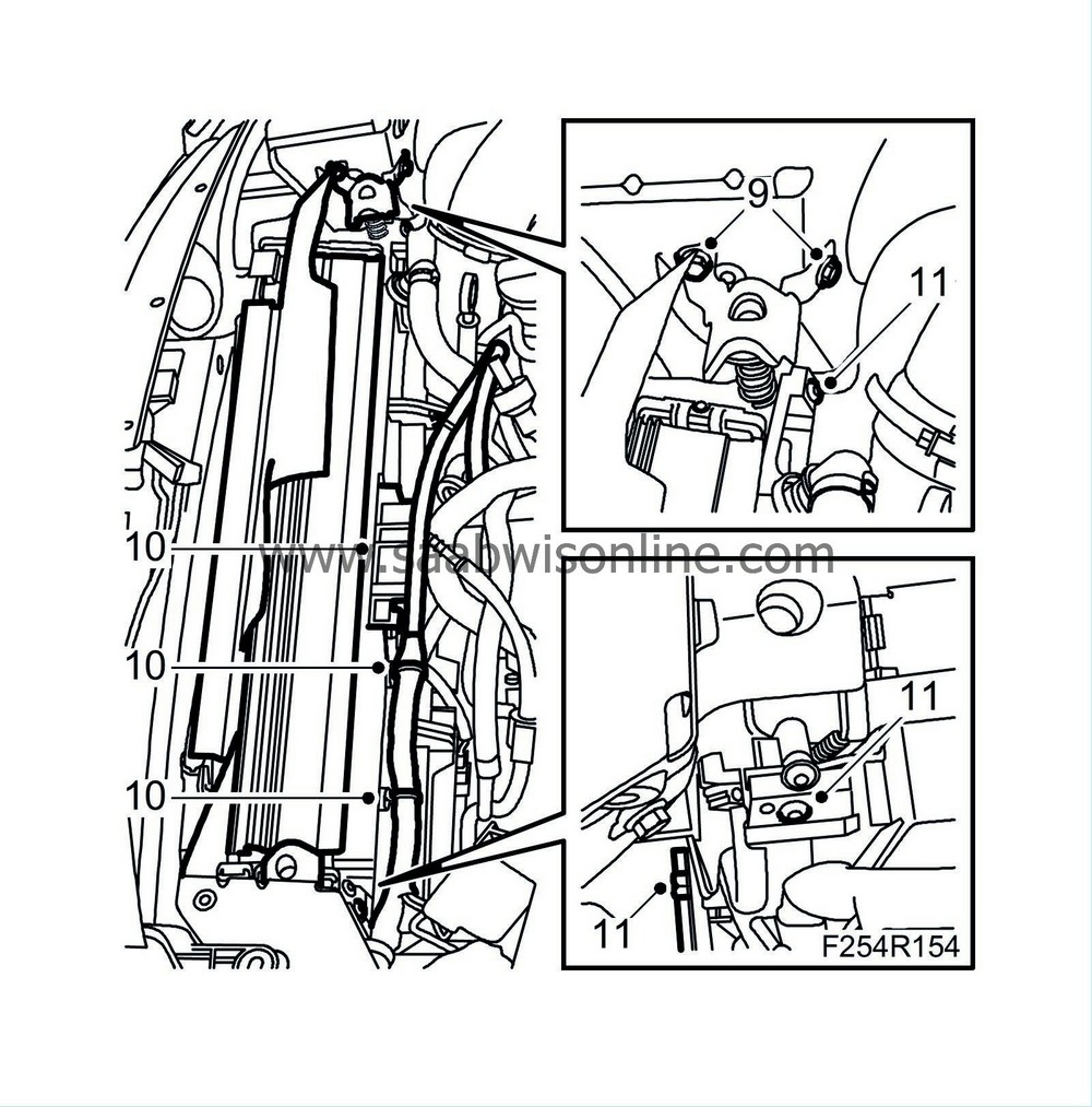
Remove the upper radiator mounting.
|
|
| 10. |
Unplug the radiator fan connectors and detach the wiring harness from the fan cowling.
|
|
| 11. |
Remove the bolts of the lower turbocharger delivery pipe and the fan cowling.
|
|
| 12. |
Press the radiator assembly forward and remove the fan cowling.
|
|
| 13. |
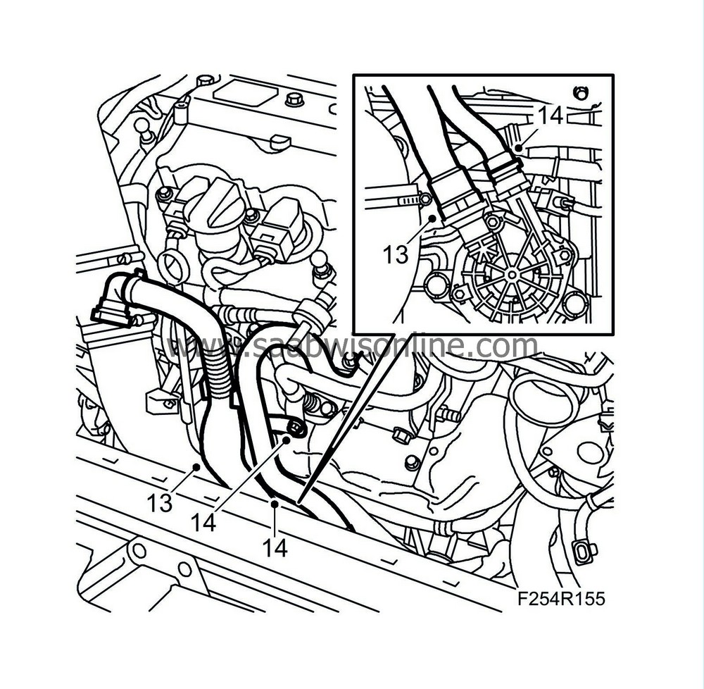
Detach the intake manifold of the secondary air injection pump from the pump.
|
|
| 14. |
Detach the discharge pipe of the secondary air injection pump from the pump.
|
|
| 15. |
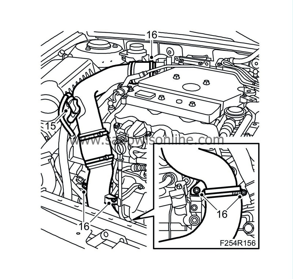
Unplug the intake air sensor connector (688).
|
|
| 16. |
Remove the turbocharger delivery pipe.
|
|
| 17. |
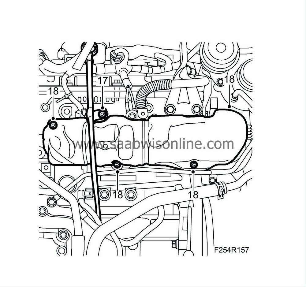
Remove the screw holding the dipstick tube.
|
|
| 18. |
Remove the heat shield of the front exhaust manifold.
|
|||||||
| 19. |
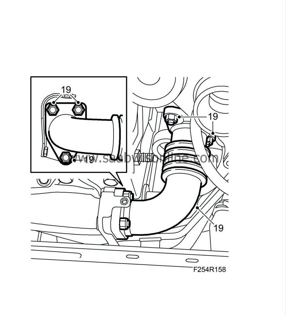
Detach the intermediate exhaust pipe from the turbocharger and the front exhaust manifold.
|
|
| To fit |
| 1. |
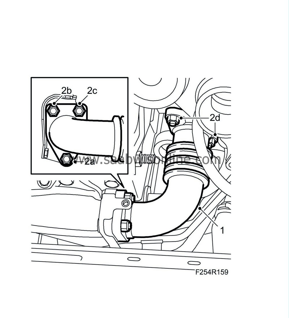
Attach the intermediate exhaust pipe to the front exhaust manifold and the turbocharger. Use a new gasket and coat the studs with 90 513 210 Universal paste. Fit all nuts.
|
||||||||||
| 3. |
Fit the heat shield of the front exhaust manifold.
Tightening torque 10 Nm (7 lbf ft) 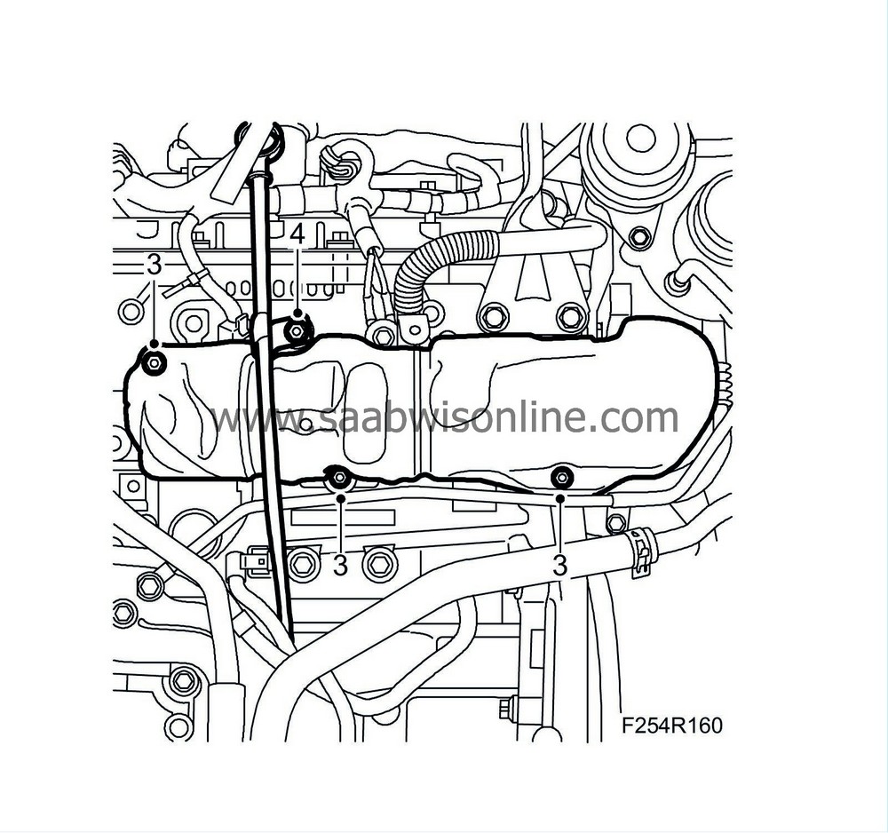
|
|
| 4. |
Fit the screw holding the dipstick tube.
Tightening torque 10 Nm (7 lbf ft) |
|
| 5. |
Fit the turbocharger delivery pipe.
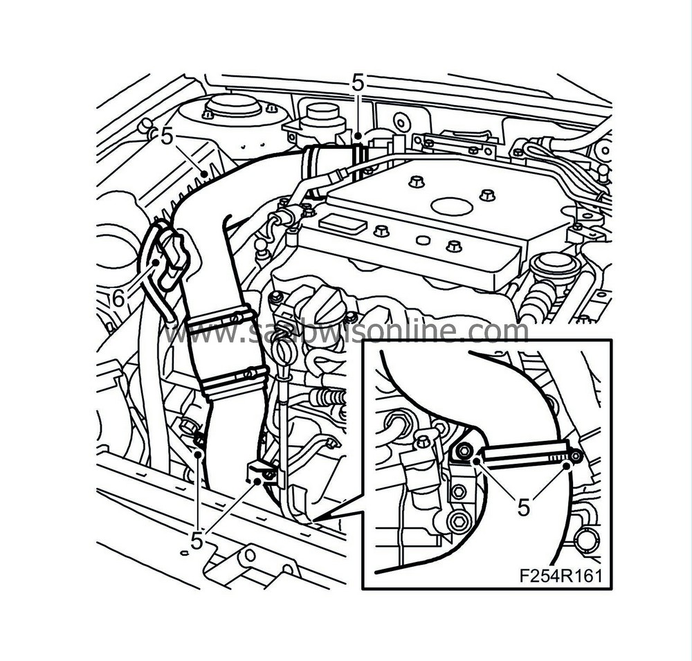
|
|
| 6. |
Plug in the intake air sensor connector (688).
|
|
| 7. |
Attach the discharge pipe of the secondary air injection pump.
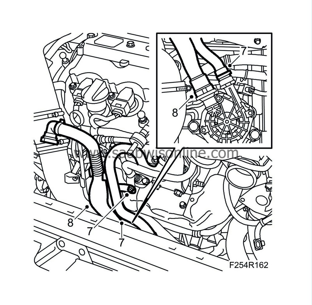
|
|
| 8. |
Attach the secondary air injection pump's intake manifold to the pump.
|
|
| 9. |
Press the radiator assembly forward and position the fan cowling.
|
|
| 10. |
Fit the bolts of the lower turbocharger delivery pipe and the fan cowling.
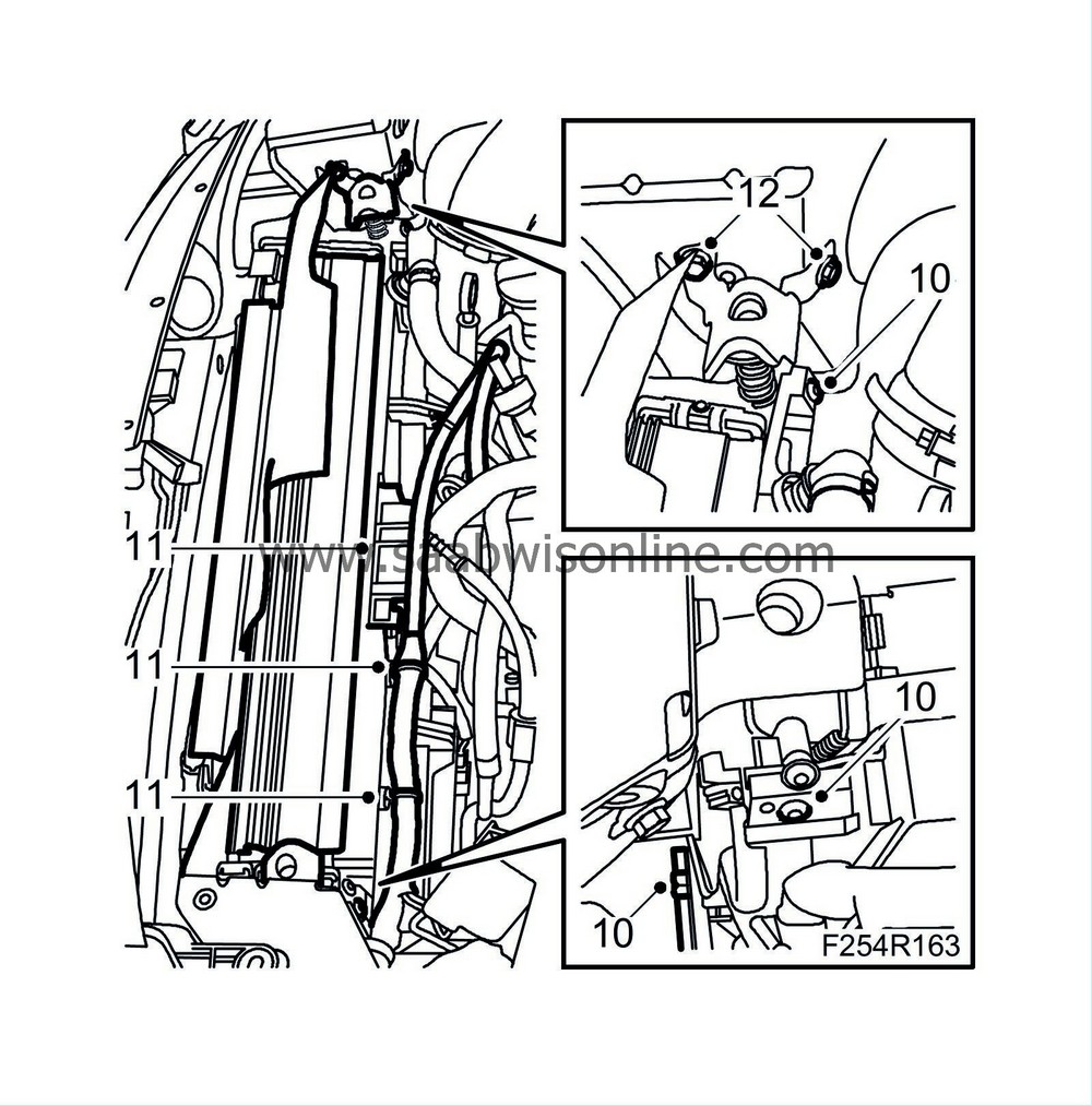
|
|
| 11. |
Plug in the radiator fan connectors and attach the wiring harness to the fan cowling.
|
|
| 12. |
Fit the upper radiator mounting.
|
|
| 13. |
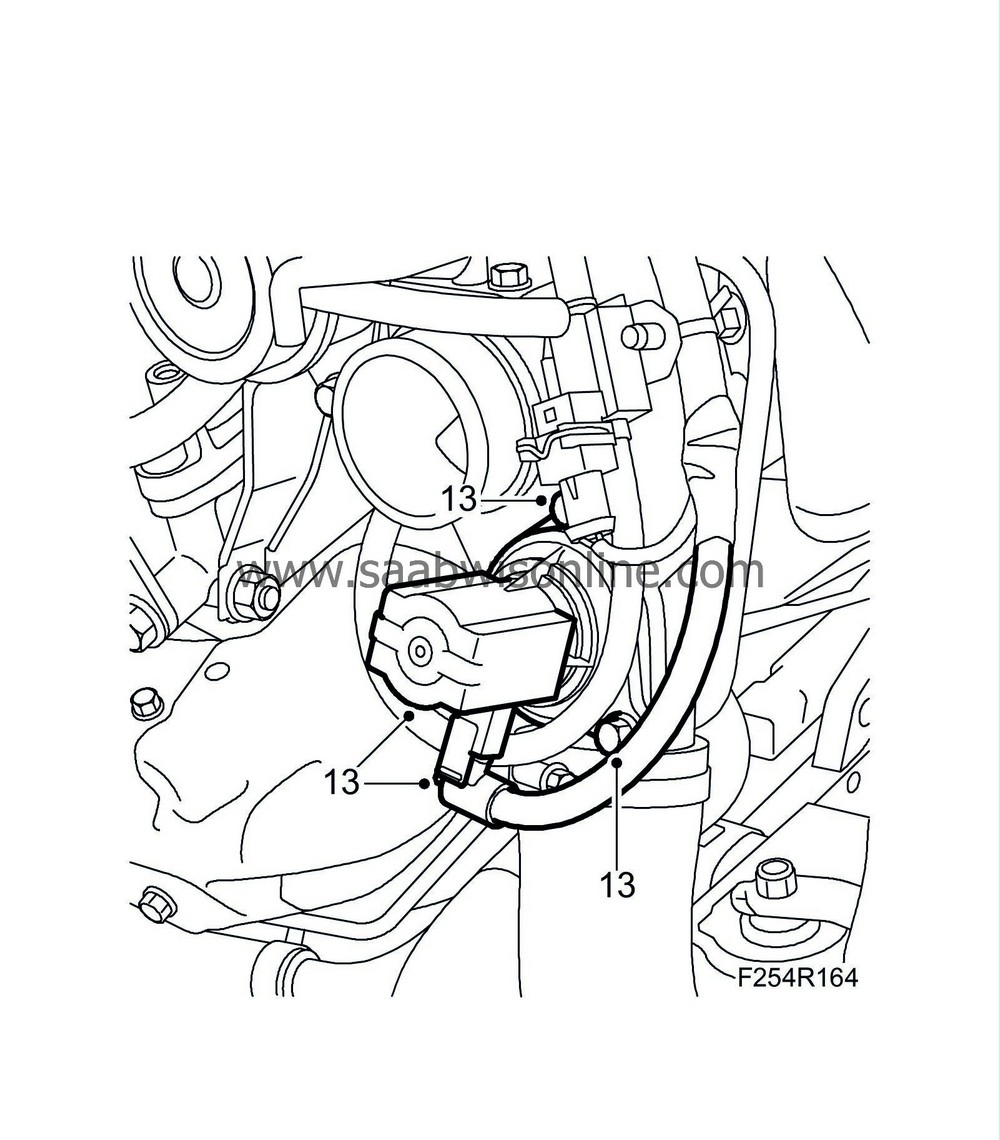
Fit the bypass valve and plug in the connector.
|
|
| 14. |
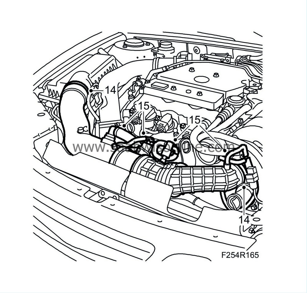
Attach the turbocharger intake manifold to the turbocharger and the air cleaner casing cover.
|
|
| 15. |
Plug in the mass air flow sensor connector. Attach the secondary air pipe, the delivery hose to the turbocharger intake manifold and the crankcase ventilation pipes.
|
|
| 16. |
Fit
Upper radiator member, B284
.
|
|
| 17. |
Fit
Battery cover, bottom, B284
.
|
|
| 18. |
Fit the battery.
|
|
| 19. |
Fit the battery cable.
|
|
| 20. |
Fit the battery cover and the engine cover.
|
|
| 21. |
Remove the wing covers and restore car electrical functions, see
After disconnecting the battery
.
|
|
| 22. |
Start the engine and check for any exhaust leakage.
|
|

 Warning
