Subframe, replacement, 4WD
|
|
Subframe, replacement, 4WD
|
|
4.
|
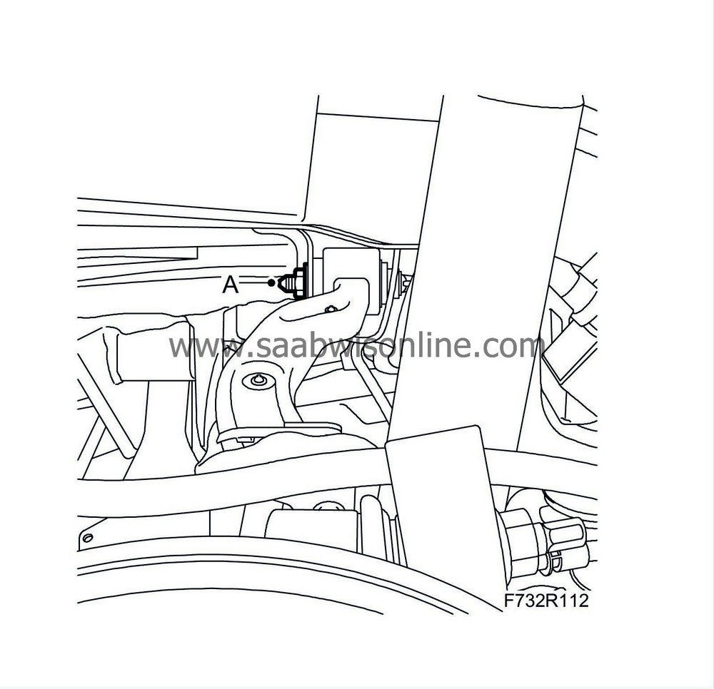
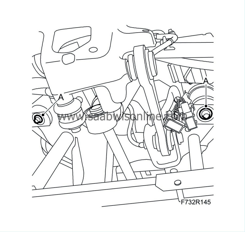
Remove the bolts (A) securing the upper suspension arms to the subframe.
|
|
5.
|
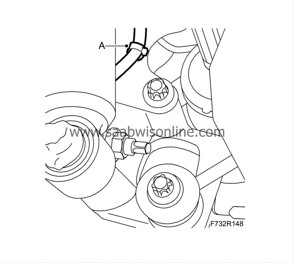
Remove the wheel sensor's wiring harness (A) from the upper suspension arm on both sides.

|
|
6.
|
Remove the wheel sensor wiring harness (A) from the longitudinal link on both sides.
|
|
7.
|
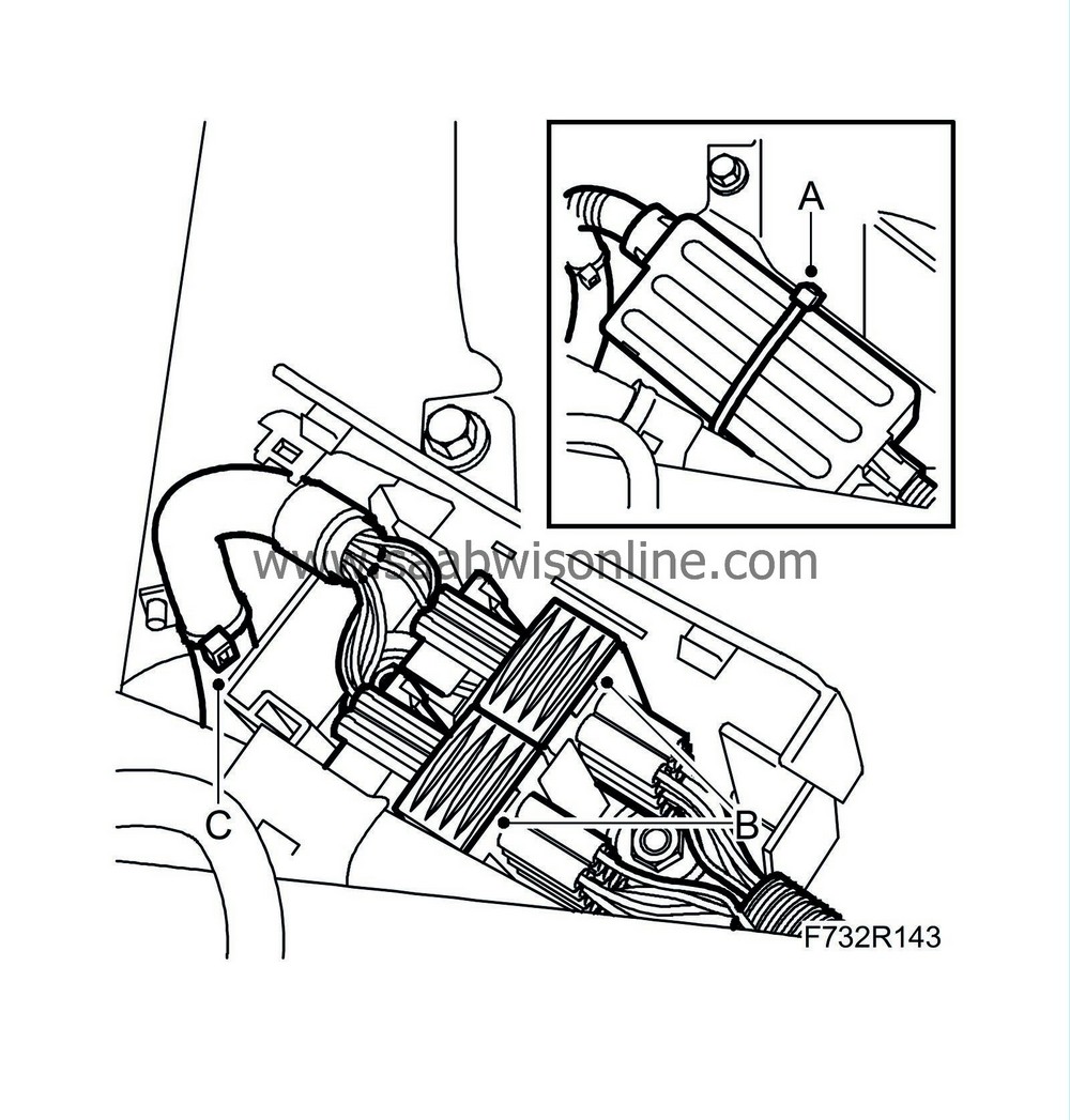
Cut the strap (A) and open the protective case. Detach and unplug the connector housings (B). Remove the wiring harness from the clip (C).
|
|
8.
|
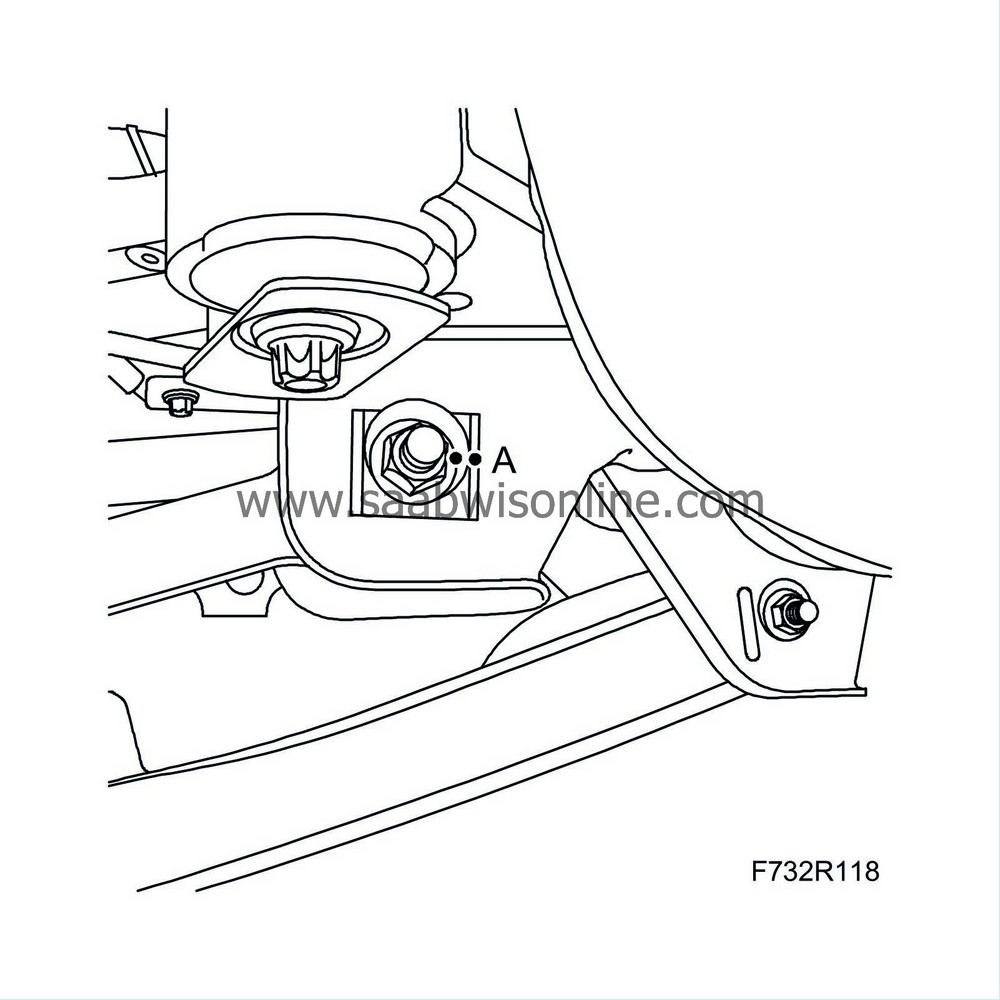
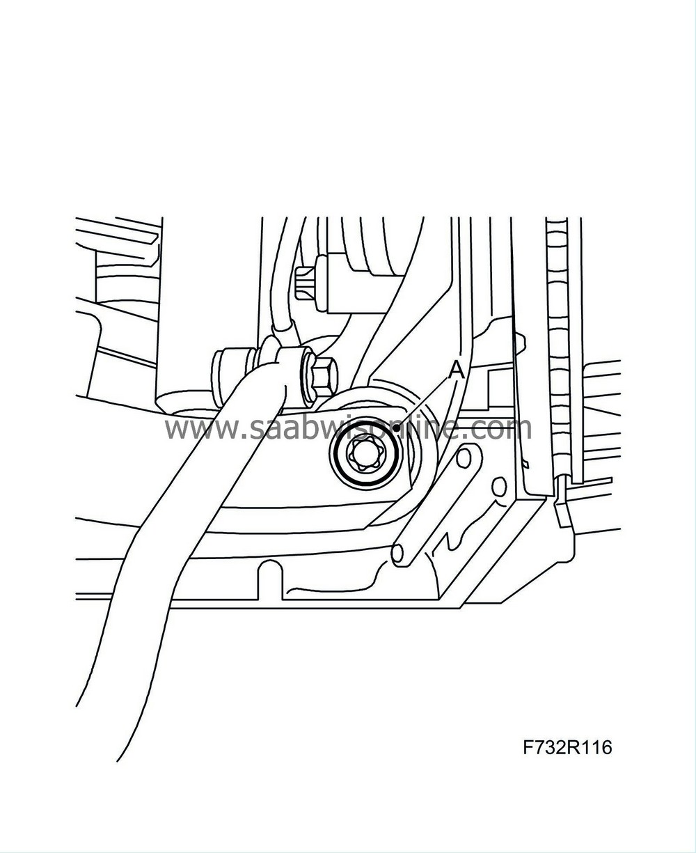
Mark with a centre punch, remove the toe-in link adjuster screw (A) and lower the toe-in link on both sides.
|
|
10.
|
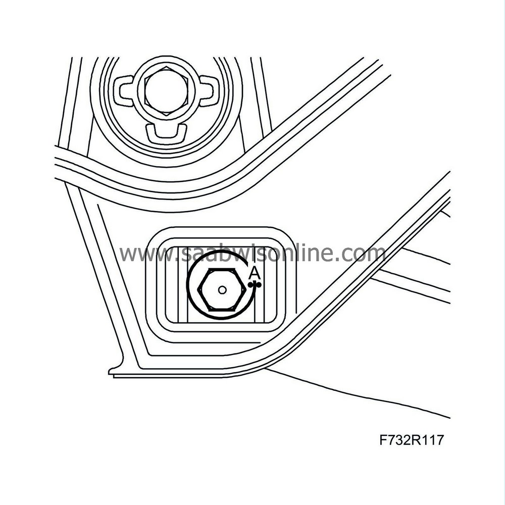
Remove the bolts (A) securing the subframe to the body on both sides.
|
|
11.
|
Lower the trolley lift with the subframe. Retain the washers between the subframe bushes and the body.
|
|
12.
|
Cars with Xenon lights:
Remove the level sensor.
|
|
13.
|
Remove the wiring harness from the subframe.
|
|
2.
|
Cars with Xenon lights:
Fit the level sensor.
|
|
3.
|
Fit the wiring harness on the subframe.
|
|
4.
|
Place washers (A) on the subframe bushes. Raise the subframe. The jig's locating pins (B) must fit in the holes in the body.

|
|
5.
|
Lift the subframe so that the inner sections of the bushes are pressing against the body. Fit the subframe bolts (A) on both sides.
Tightening torque 75 Nm +135° (55 lbf ft +135°)
|
|
6.
|
Lower and pull away the trolley lift.
|
|
7.
|
Position the toe-in link on both sides.
|
|
8.
|
Fit the adjuster screw (A) and washer to the toe-in link. Fit a new nut on both sides, but do not tighten yet.
|
|
9.
|
Position the upper suspension arm on both sides.
|
|
10.
|
Fit the bolts for the upper suspension arm mounting to the subframe on both sides.
|
|
11.
|
Fit the wheel sensor's wiring harness (A) to the upper suspension arm on both sides.
|
|
12.
|
Fit the wheel sensor wiring harness (A) to the longitudinal link on both sides.
|
|
13.
|
Plug in and fit the wiring harness (B) in the protective case. Close the cover and fit straps (A) around the case. Fit the wiring harness clips (C).
|
|
14.
|
Fit the lower suspension arms on both sides. Insert the bolts.
|
|
16.
|
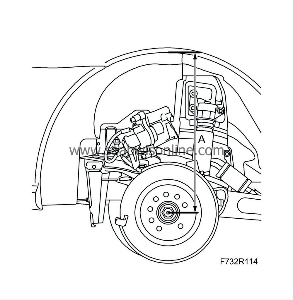
Lift the steering swivel member to normal position 374 mm,
9-3X
: 390 mm (A) between the centre of the drive shaft and the edge of the wing.
|
|
17.
|
Tighten the nut (A) for the suspension arm mounting to the subframe on both sides.
Tightening torque 75 Nm +90°(55 lbf ft + 90°)
|
|
18.
|
Tighten the adjuster screw nut (A). Make sure that the marking on the adjuster screw ends up in the right position on both sides.
Tightening torque 75 Nm +60° (55 lbf ft +60°)
|
|
19.
|
Tighten the nut (A) for the suspension arm mounting to the steering swivel member on both sides.
Tightening torque 75 Nm +90° (55 lbf ft +90°)
|
|
20.
|
Tighten the nut (A) on the lower suspension arm's adjuster screw following the marking on both sides.
Tightening torque 75 Nm +60° (55 lbf ft +60°)
|


