Power unit, to fit, B207, 4WD
|
|
Power unit, to fit, B207, 4WD
|
 Warning
|
|
A large number of hoses, cables, etc., are secured with cable ties. After tightening, the ties are cut off and leave more or less sharp edges at the fastening point. Watch out for the risk of cuts due to these sharp ends on the cable ties!
|
|
|
|
|
|
|
1.
|
Position the trolley lift with power unit and adjust its position in relation to the body.
|
|
2.
|
Lift up the power unit until the inboard drive shaft universal joints are level with the wheel hubs and insert the drive shafts into the hubs. Make sure nothing gets caught or damaged.
|
|
3.
|
Lift a little higher and position the lower swivel joints to the steering swivel members. If necessary, adjust the trolley lift screws to provide even contact with the body. Check that the guide pins are positioned correctly relative the reference holes in the body.
|
|
4.
|
Position the bolts and screw them through the subframe into the body.
|
|
5.
|
Raise the engine completely and tighten the subframe bolts.
Tightening torque, subframe: 75 Nm + 135° (55 lbf ft +135°)
Tightening torque, stay: 90 Nm + 45° (66 lbf ft +45°)
|
|
6.
|
Lower the trolley lift and move it out of the way.
|
|
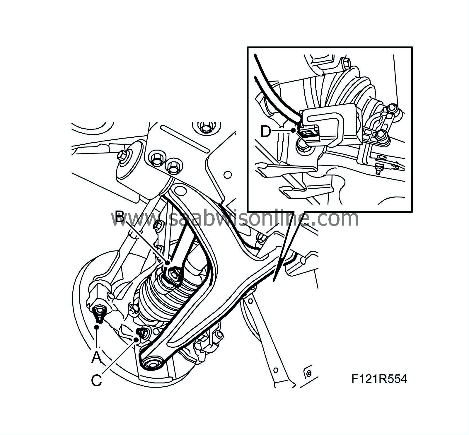
7.
|
Fit the bolts with new nuts for the lower swivel joints (C).
Tightening torque 50 Nm (37 lbf ft)
|
Important
|
|
Ensure that the steering knuckle stub is visible on the top of the steering knuckle housing before the bolt is fitted.
|
|
|
|
|
8.
|
Position the anti-roll bar's lower links (B) and tighten them while gripping the flats with a thin spanner.
Tightening torque 64 Nm (47 lbf ft)
|
|
9.
|
Position the outboard steering links and tighten them (A).
Tightening torque 35 Nm (26 lbf ft)
|
|
10.
|
Attach the connector (D) and fit the cable tie for the angle sensor (option).
|
|
11.
|
Adjust the support on KM-6313 Centring fixture, subframe - engine, about 10 mm upwards, see Centring tool, engine and subframe, 4WD, KM 6313-300, no higher than to the groove on the support's thread.
|
|
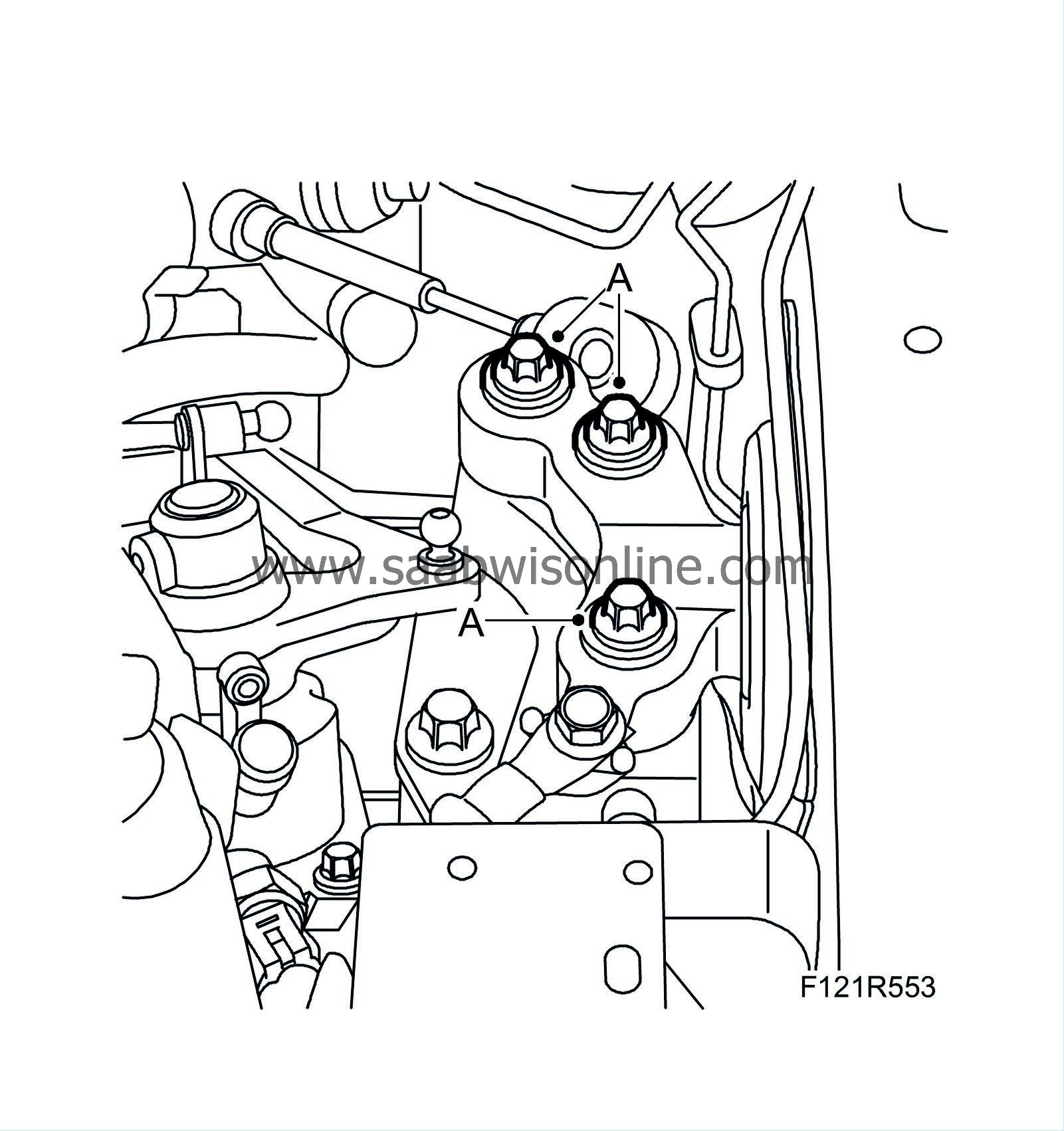
13.
|
Fit the left-hand engine mounting (A).
Tightening torque: 70 Nm +45° (52 lbf ft +45°)
|
|
14.
|
Fit the right engine mounting (A).
Tightening torque to bracket: 70 Nm +60° (52 lbf ft +60°)
Tightening torque to body 40 Nm +60° (30 lbf ft +60°).
|
|
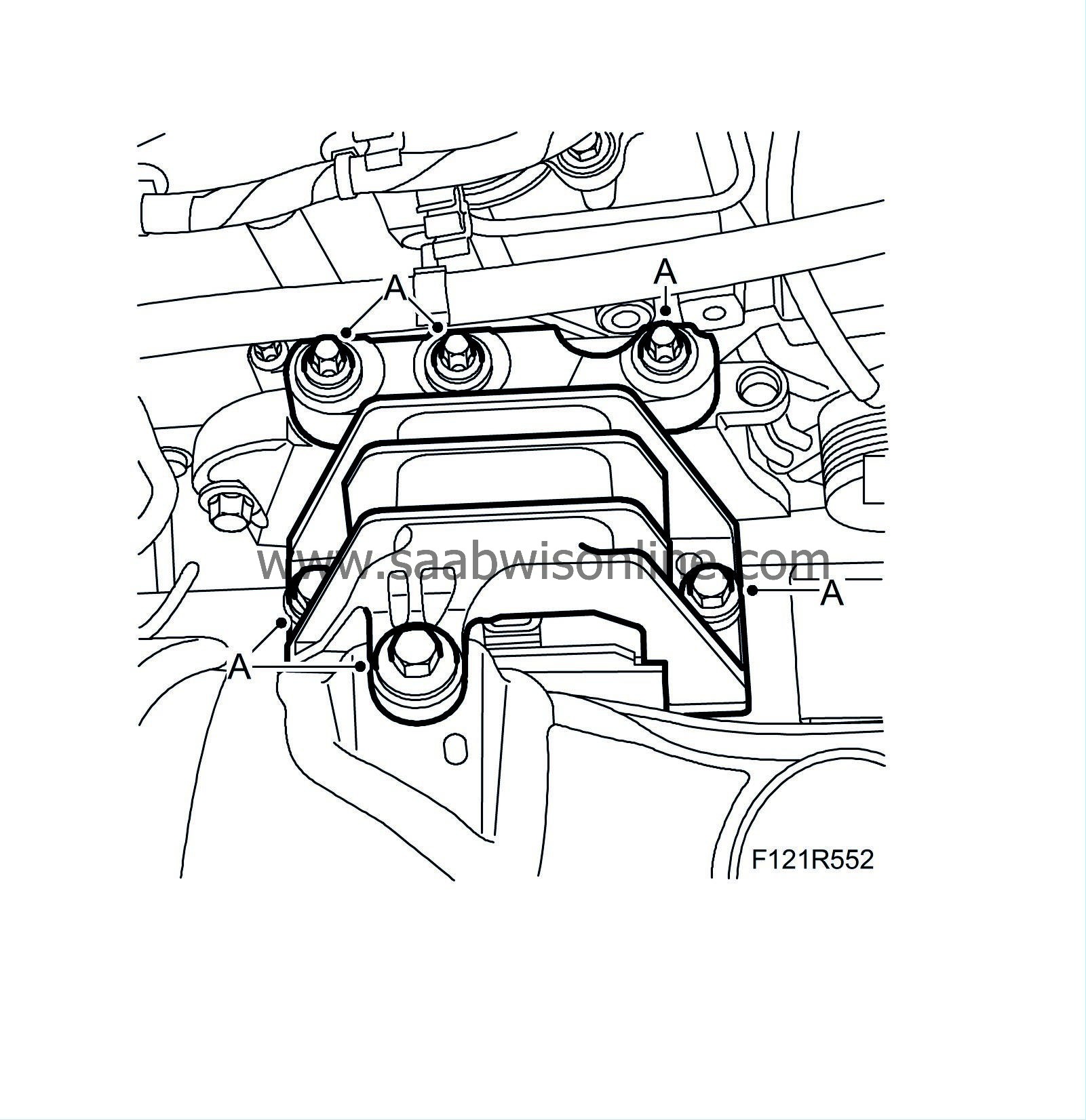
16.
|
Remove KM 6313 Centring fixture, subframe - engine.
|
|
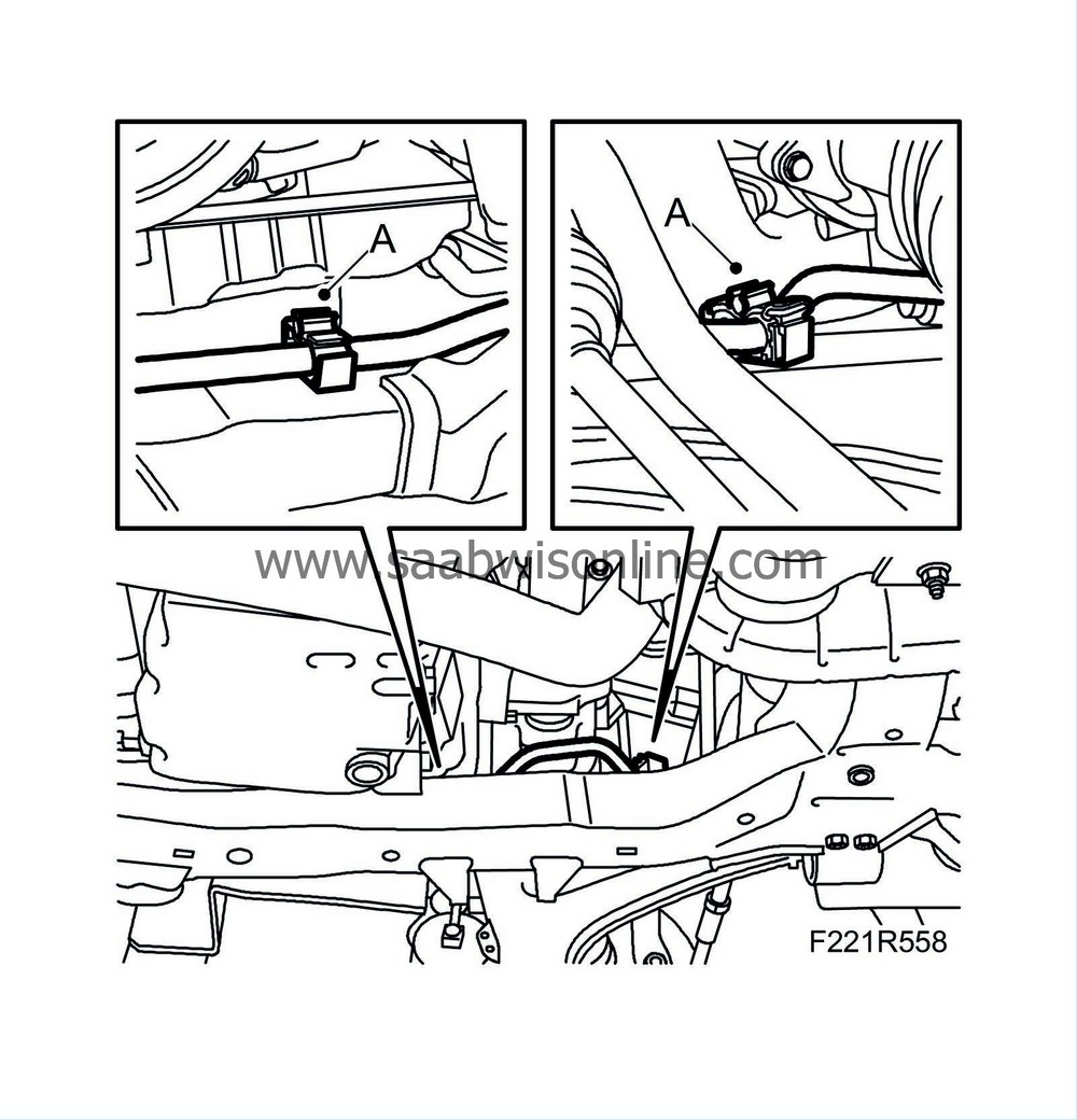
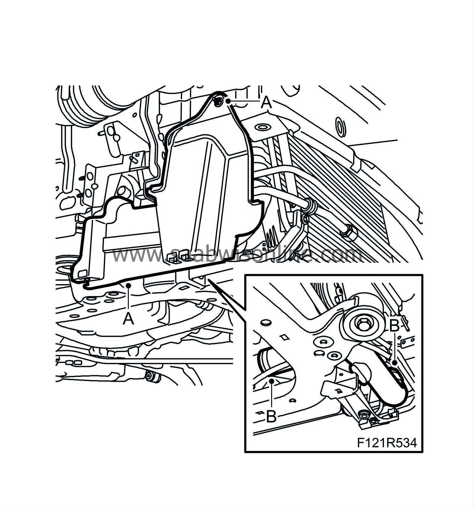
17.
|
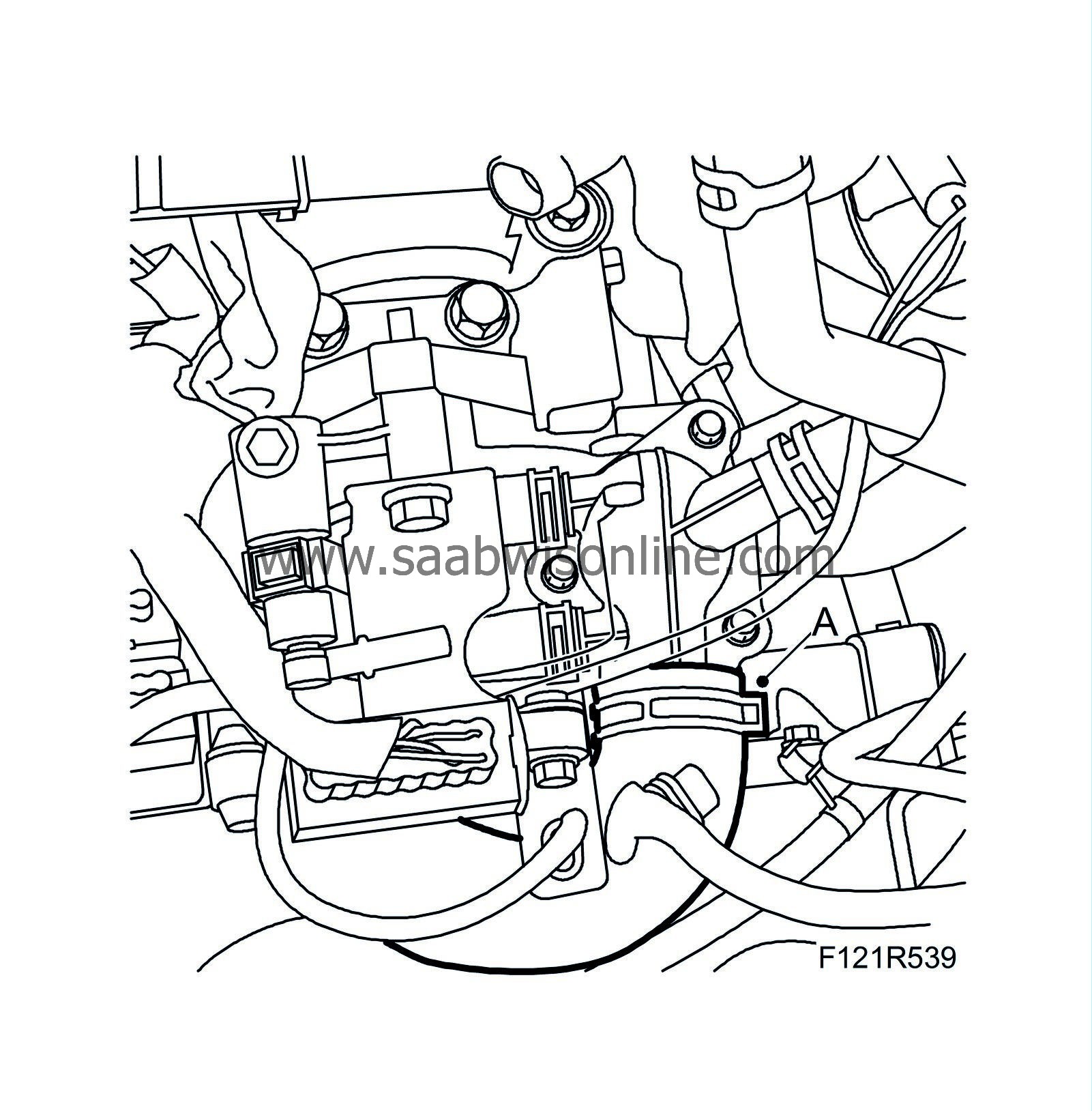
Secure the power steering pipe to the subframe with the clips (A).
|
|
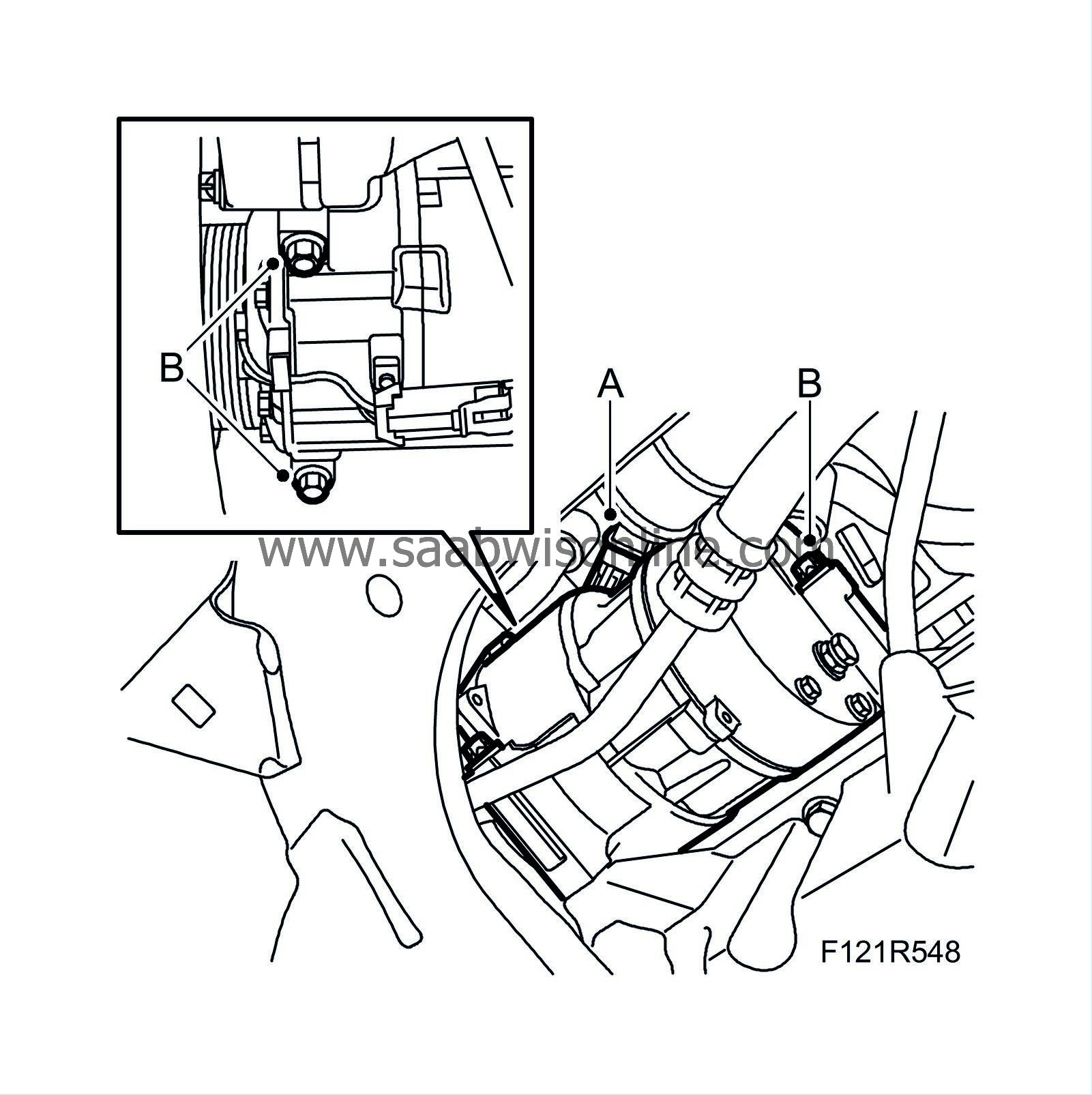
18.
|
Fit the A/C compressor retaining bolts (B) and plug in the A/C compressor connector (A).
Tightening torque 20 Nm (15 lbf ft)
|
|
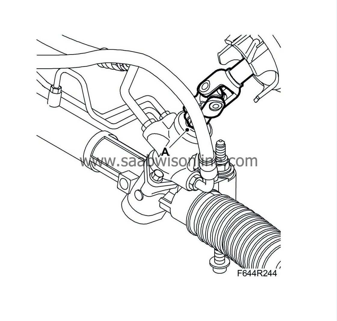
20.
|
Connect the steering shaft (A) to the steering gear. Use thread locking adhesive.
Tightening torque 30 Nm (22 lbf ft)
Use locking fluid on the threads.
|
|
21.
|
Fit the hose (B) between the charge air cooler and the charge air pipe and fit the cover (A) on the right-hand side.
|
|
23.
|
Lower the car.
|
Warning
|
|
The work involved in removing the fuel pipe requires working with the vehicle's fuel system. The following points should therefore be heeded in conjunction with these measures:
|
|
• Have a class BE fire extinguisher on hand! Be aware of the risk of sparks, i.e. in connection with electric circuits, short-circuiting, etc.
|
|
• Absolutely No Smoking!
|
|
• Ensure good ventilation! If there is approved ventilation for evacuating fuel fumes then this must be used.
|
|
• Wear protective gloves! Prolonged exposure of the hands to fuel can cause irritation to the skin.
|
|
• Wear protective goggles.
|
|
|
|
|
|
|
|
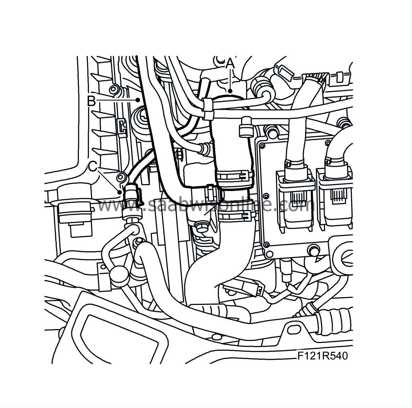
24.
|
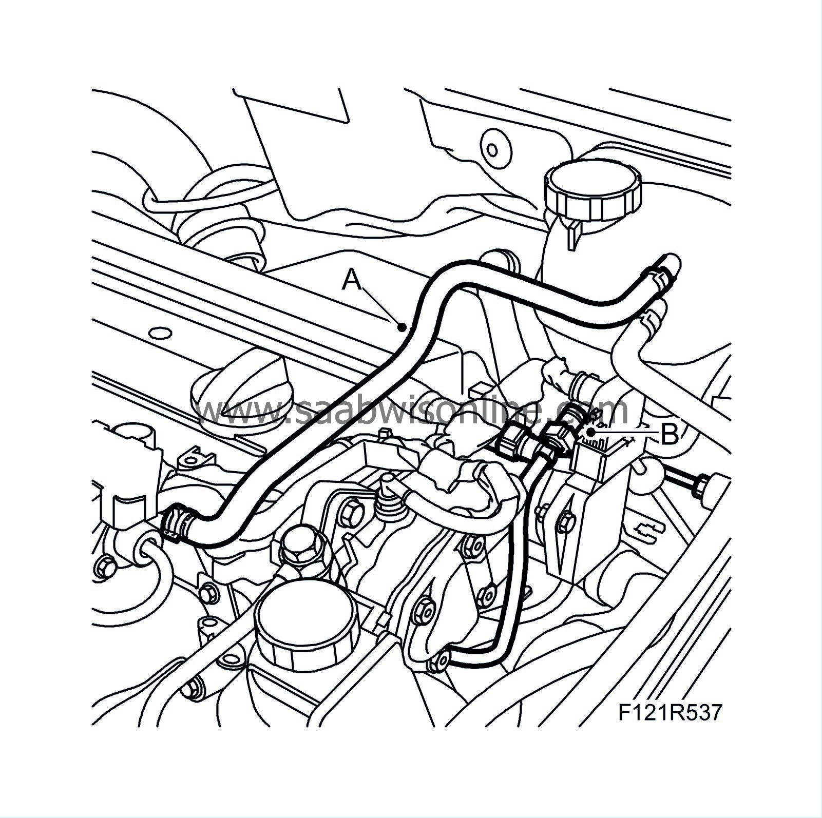
Connect the quick coupling (B) for the breather line.
|
|
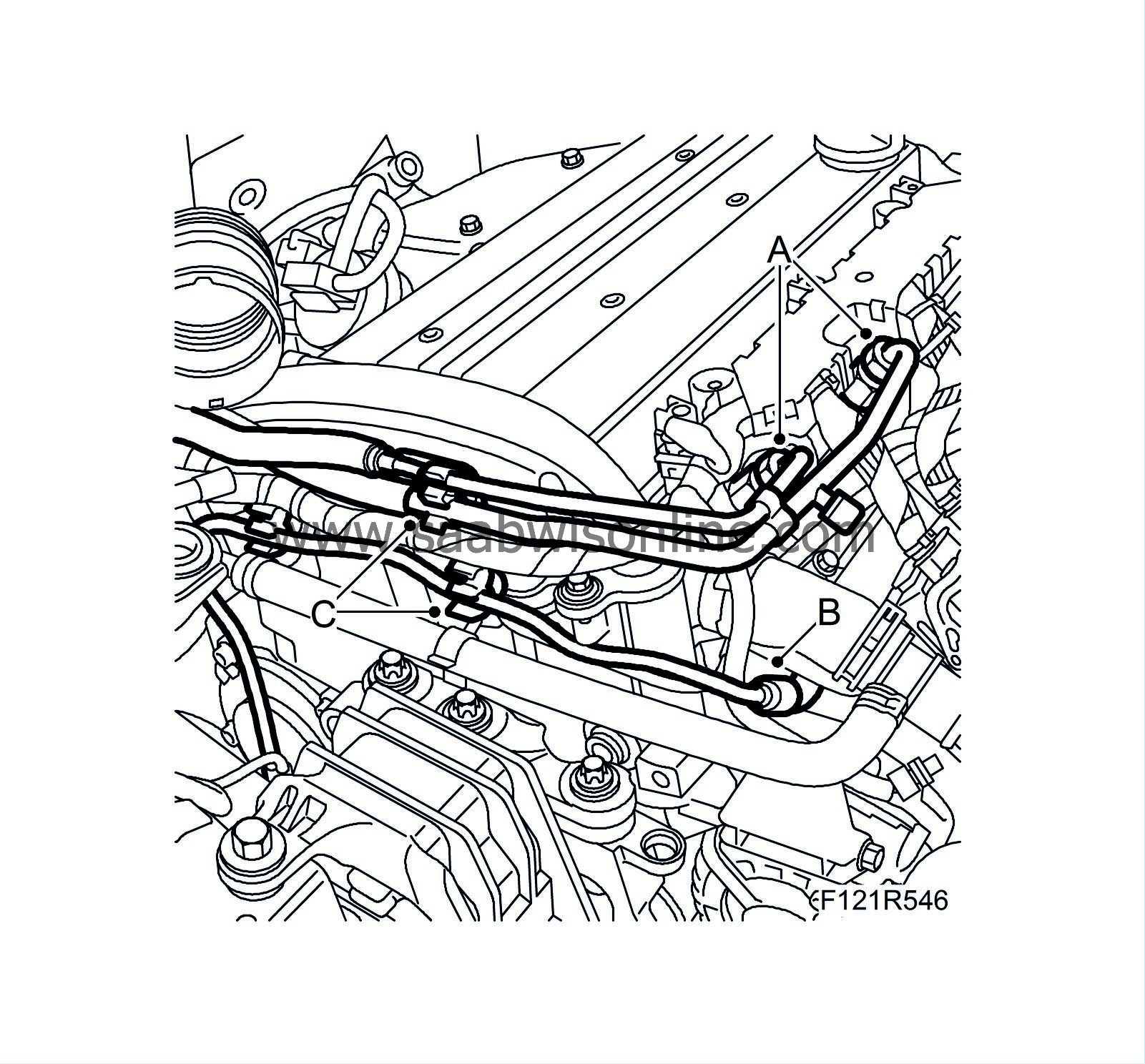
25.
|
Remove the plug and attach the two fuel lines (A) to the fuel rail. Counterhold at the lower nut, and affix (C) the fuel lines and the bleeder lines at the camshaft cover.
|
|
26.
|
Fit the upper radiator hose (A) to the engine and the hose (B) to the turbo.
|
|
27.
|
Attach the connector (C) for the A/C pressure sensor.
|
|
28.
|
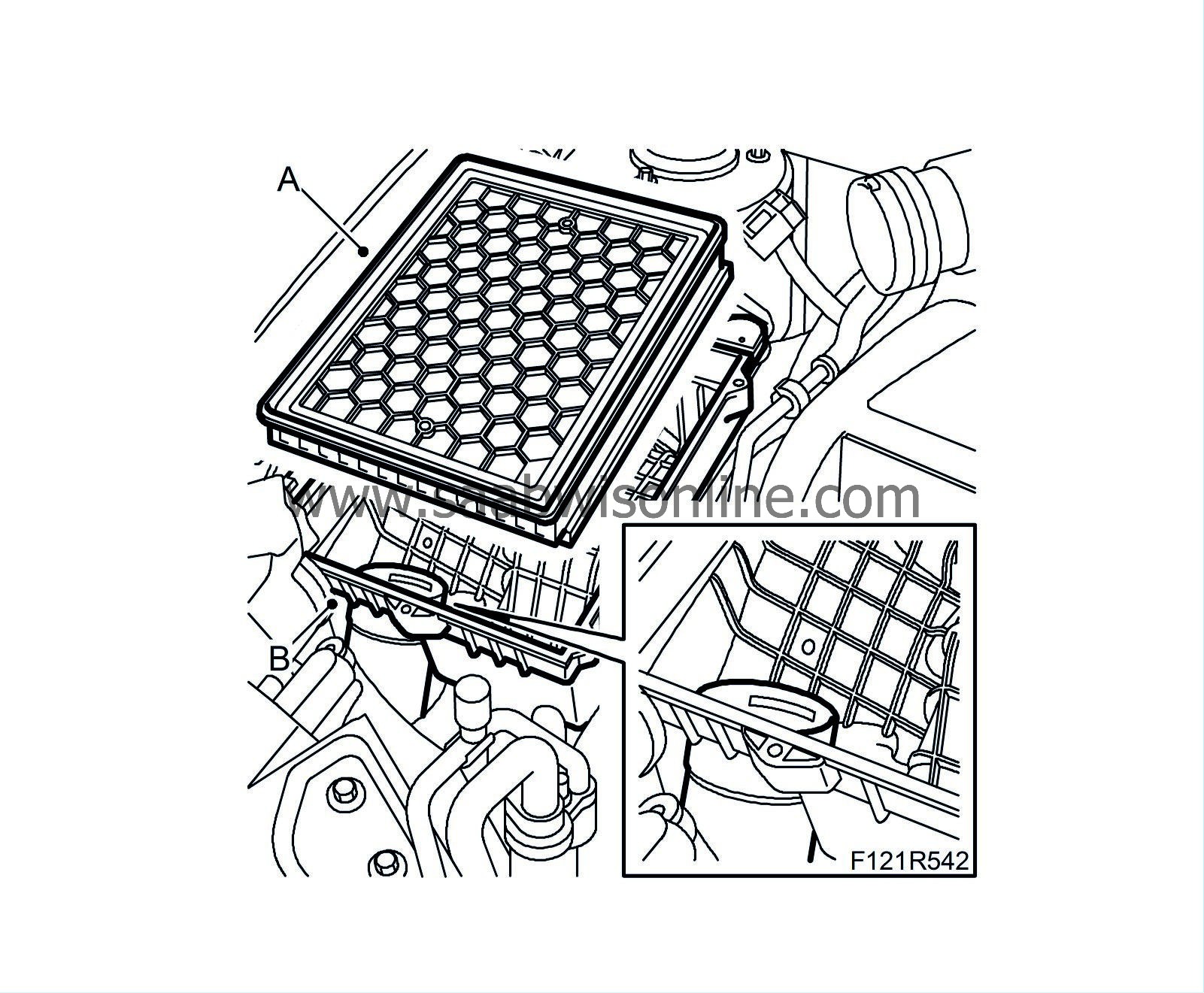
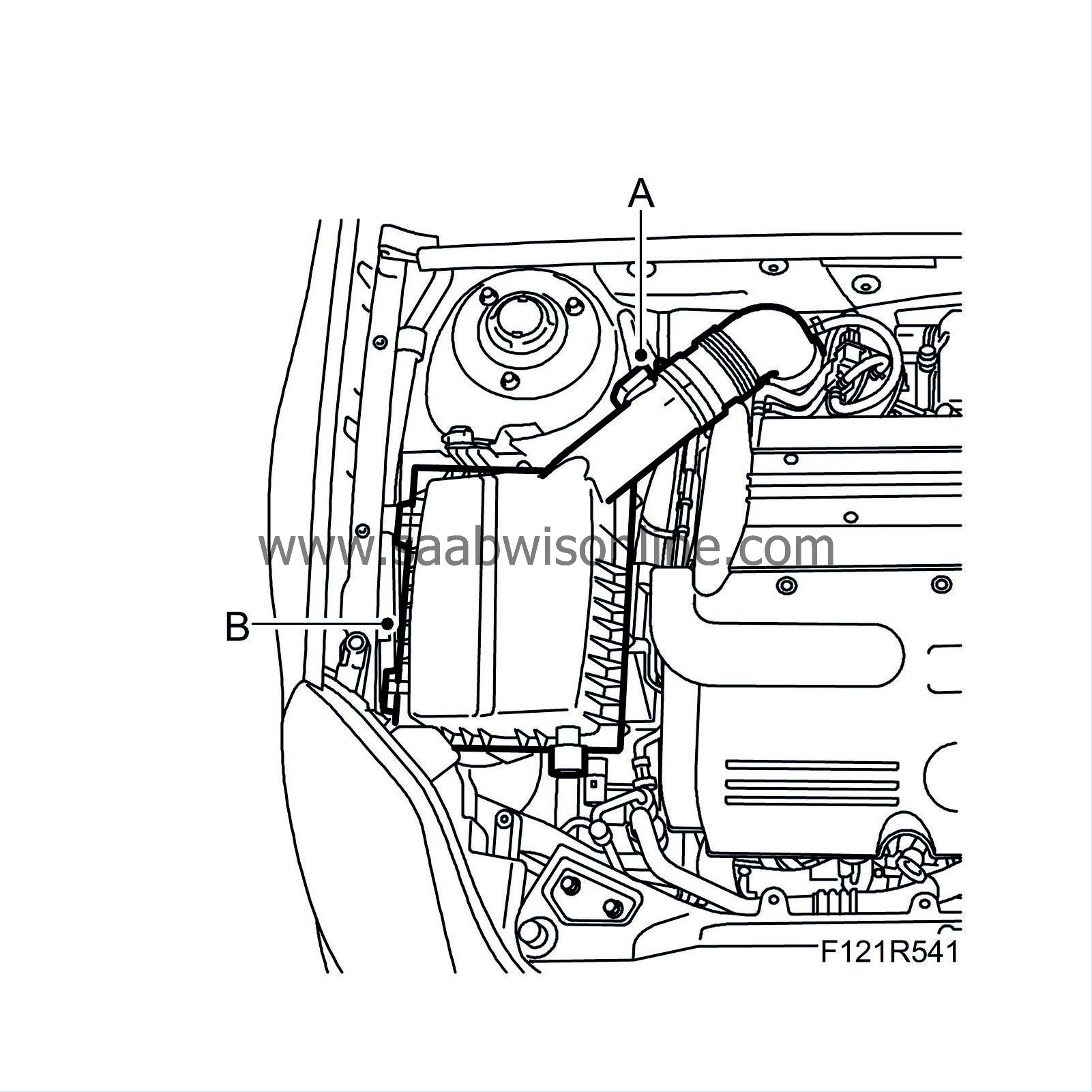
Connect the inlet hose (B), fit the air cleaner casing and the air filter (A).
|
|
29.
|
Fit the air filter cover (B) and the mass air flow sensor connector (A).
|
|
30.
|
Man:
Fit the quick coupling (B) on the clutch slave cylinder. Remove the hose pinch-off pliers.

|
|
31.
|
Attach the gear cables (A) to the gearbox.
Aut:
only one cable.
|
|
32.
|
Man:
If necessary, bleed the clutch as described in Bleeding the clutch hydraulic system in situ.
|
|
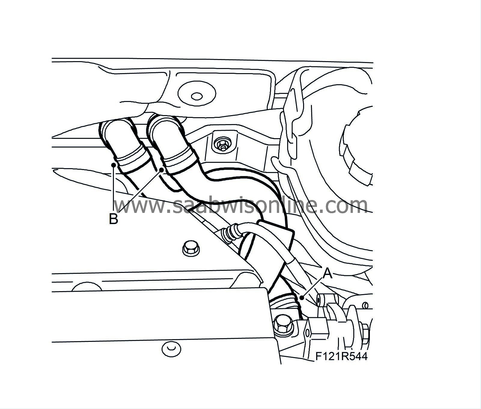
34.
|
Connect the coolant hoses' quick couplings (B).
|
|
35.
|
Connect the coolant hose (A) to the thermostat housing.
|
|
36.
|
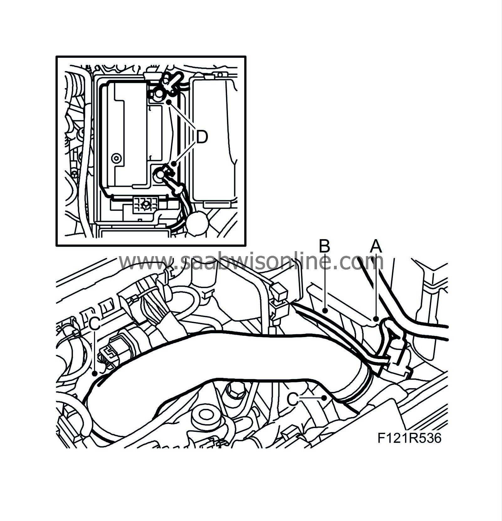
Fit the engine harness (E) to the body and the 2-pin connector housing.

|
|
37.
|
Fit the engine harness connector in the electrical centre and tighten the screw (D).
|
|
38.
|
Attach the positive cable (C) to the positive terminal of the battery.
|
|
39.
|
Fit the two retaining bolts (B) for the electrical centre.
|
|
40.
|
Aut:
Attach the oil pipes to the radiator.
|
|
41.
|
Plug in the connector (A) on the left structural member.
|
|
42.
|
Man:
Fit the electrical connection for the reversing light switch.
|
|
43.
|
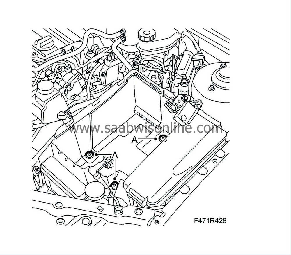
Fit the lower radiator hose (A) to the thermostat housing, fit a cable tie to the engine wiring harness.
|
|
44.
|
Fit the battery tray (A), plug in the bonnet switch connector and attach the cable clip.
|
|
45.
|
Install the electrical centre in front of the battery tray.
|
|
46.
|
Aut:
Plug in the connector (B) beneath the control module. Fit the cover with the control module and plug in the connectors (A) for the TCM control module.
|
|
47.
|
Connect the vacuum hose quick coupling (B) to the vacuum pump.
|
|
48.
|
Connect the bleeder hose (A) to the engine.
|
|
49.
|
Fit the battery (D).
|
|
50.
|
Attach the charge air hose (C) to the throttle body and the charge air pipe.
|
Important
|
|
To reduce the risk of hoses mounted on the delivery side of the turbocharger coming loose due to low friction at high air pressure, the hoses and connecting pieces must be cleaned thoroughly before fitting. Use a rag dampened with 93 160 907 Motip Dupli cleaning agent to wipe clean inside the ends of the hoses. Clean the connecting pieces as well. If hose clips are rusty or damaged, they must be replaced so the correct clamping force is maintained.
|
|
|
|
|
51.
|
Plug in the connector (A) for the pressure/temperature sensor and connect the charge air bypass valve hose (B).
|
|
52.
|
Fit the battery cover (C).

|
|
53.
|
Fit the dipstick (A) and the upper engine cover (B).
|
|
54.
|
Detach the straps from the radiator unit.
|
|
56.
|
Fit the wing liner front section, right and left-hand sides.
|
|
57.
|
Fit new nuts for the drive shafts.
|
|
58.
|
Fit the front wheels without protective washers. See
Wheels
.
|
|
59.
|
Lower the car and tighten the hub centre nuts.
Tightening torque 230 Nm (170 lbf ft).
|
|
60.
|
Press the protective washers into the wheel rim.
|
|
61.
|
Check engine oil level, top up as necessary.
|


