Spare part cylinder block, to fit, B207, 4WD
|
|
Spare part cylinder block, to fit, B207, 4WD
|
|
2.
|
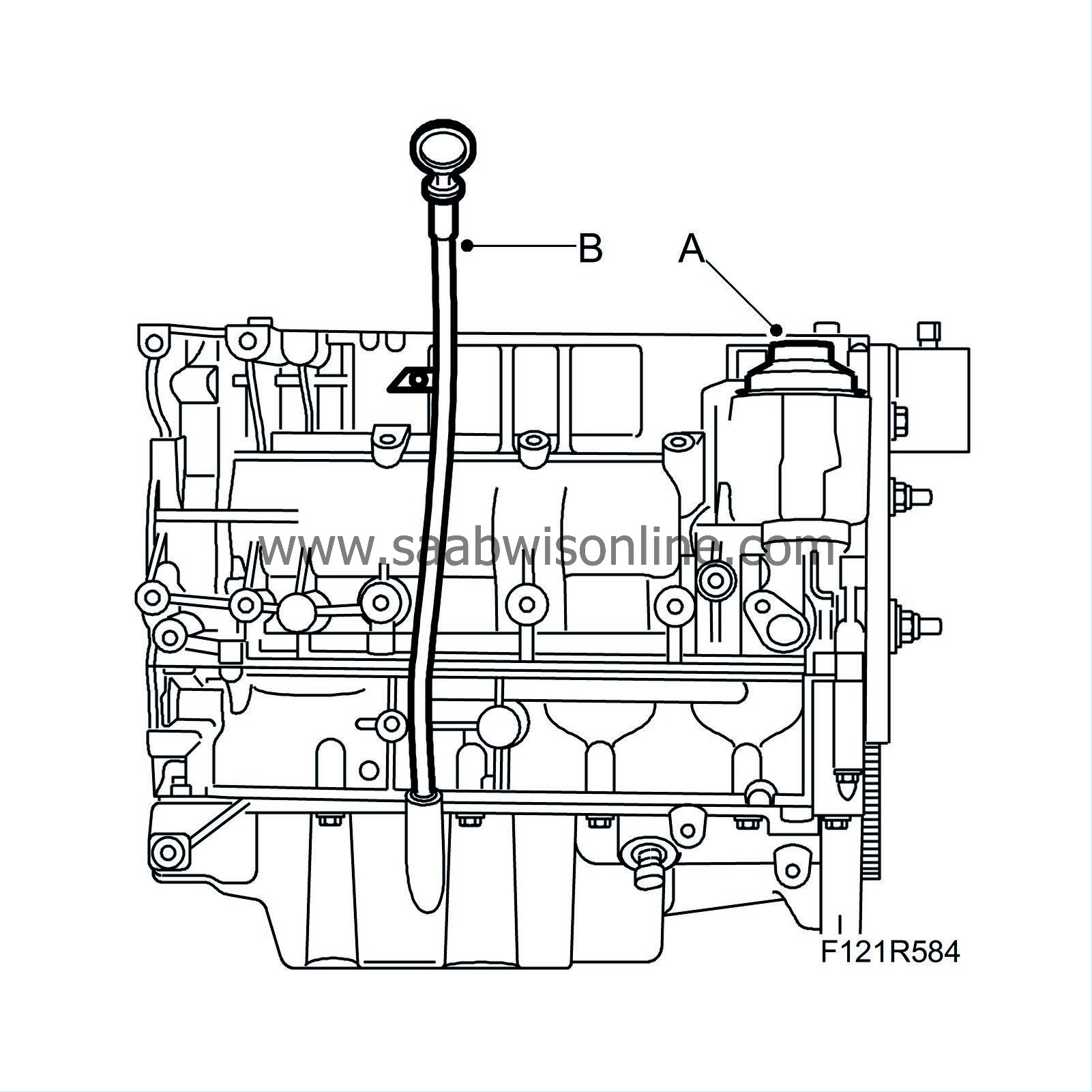
Fit the dipstick tube (B) with new O-rings.
|
|
4.
|
Check that the spare part cylinder block is zeroed using the markings on the pulley and timing cover.
|
|
5.
|
Place a new gasket on the cylinder block.
|
|
6.
|
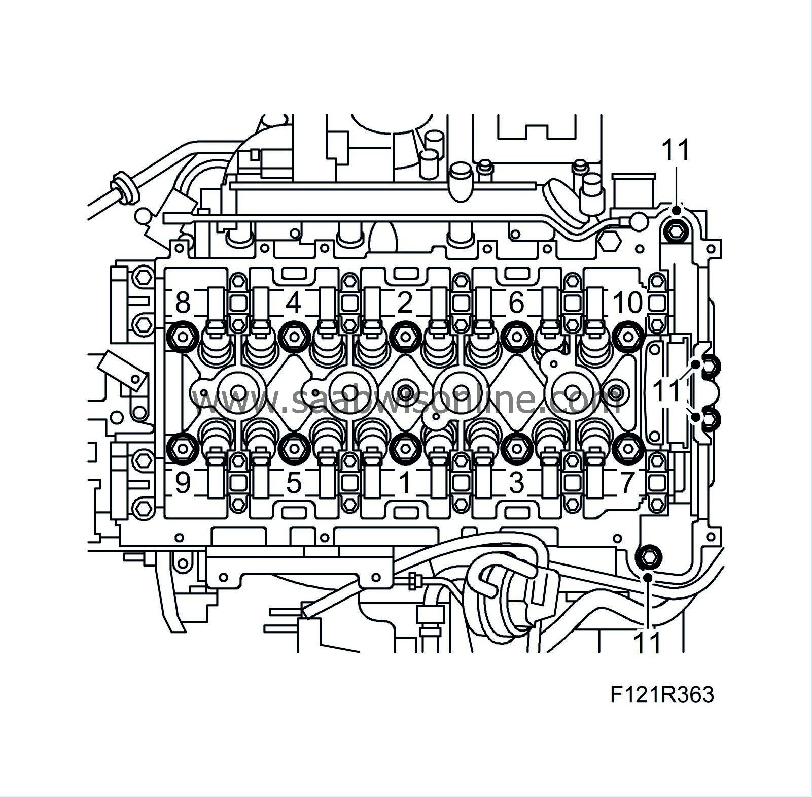
Fit the cylinder head in the order shown in the illustration. Insert the bolts carefully. The threads in the cylinder block can become damaged if they are lowered too rapidly. Make sure it fits properly onto the guide sleeves.
Tightening torque step 1, 30 Nm (22 lbf ft)
Tightening torque, step 2: 150°
Tightening torque, step 3: 15°
Tightening torque, bolts for timing section, 35 Nm (26 lbf ft)
|
|
7.
|
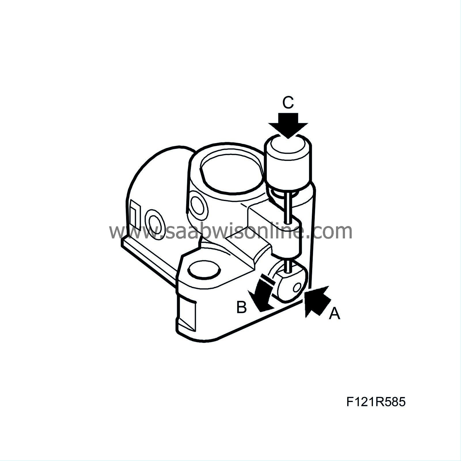
Load the chain tensioner by pressing in the plunger (A) and turning (B) to the right. Then secure with tool
83 96 392 Lock pin
(C).
|
Important
|
|
The colour markings on the balancer shaft chain must correspond with the markings on the gears.
|
|
|
|
|
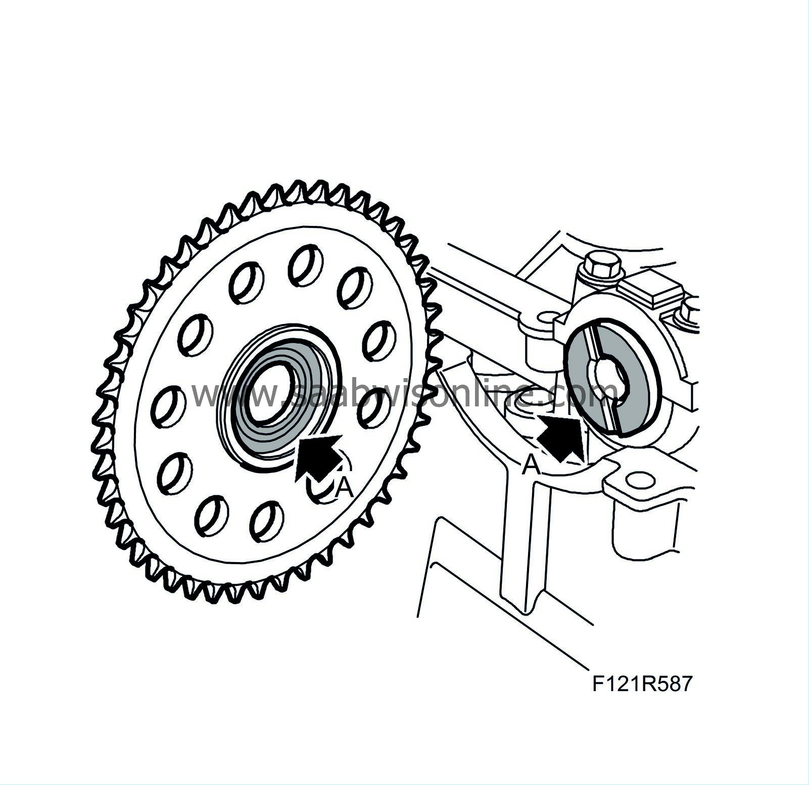
8.
|
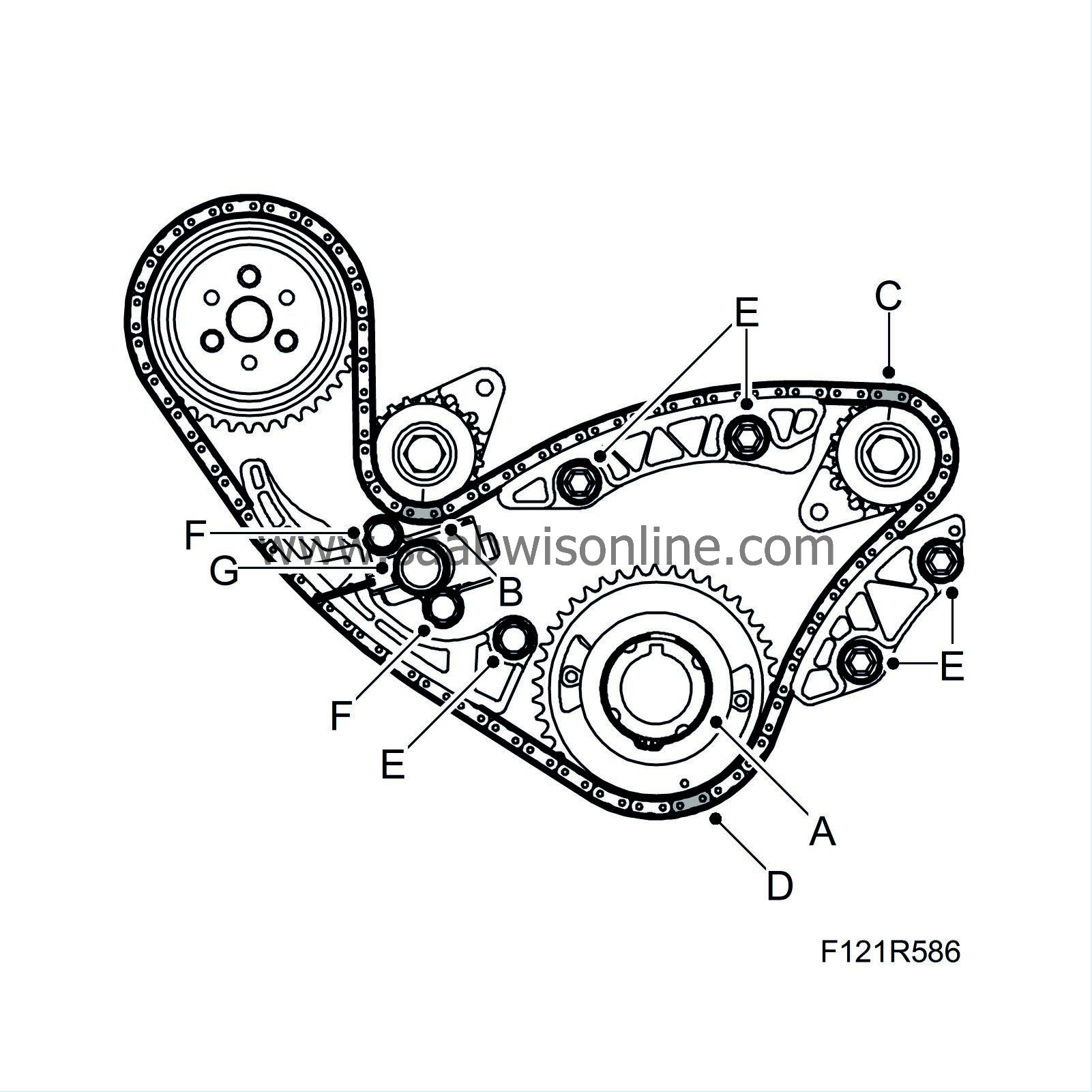
Fit the balancer shaft chain sprocket (A) and wedge. Fit the balancer shaft chain. Start fitting on the water pump pinion. Proceed as follows:
|
|
|
•
|
The silver-coloured link (B) must be fitted to the exhaust side's balancer shaft sprocket.
|
|
|
•
|
The copper-coloured link (C) must be fitted to the intake side's balancer shaft sprocket.
|
|
|
•
|
The silver-coloured link (B) must be fitted to crankshaft sprocket.
|
|
9.
|
Fit the balancer shaft chain guide rails (E). Use thread locking adhesive.
Tightening torque 10 Nm (7 lbf ft)
|
|
10.
|
Fit the chain tensioner (F). Use thread locking adhesive.
Tightening torque 10 Nm (7 lbf ft)
|
|
11.
|
Remove the tool from the tensioner (G). Press the tensioner guide rail to check that backward movement of the plunger is prevented.
|
|
12.
|
Fit the crankshaft sprocket.
|
|
13.
|
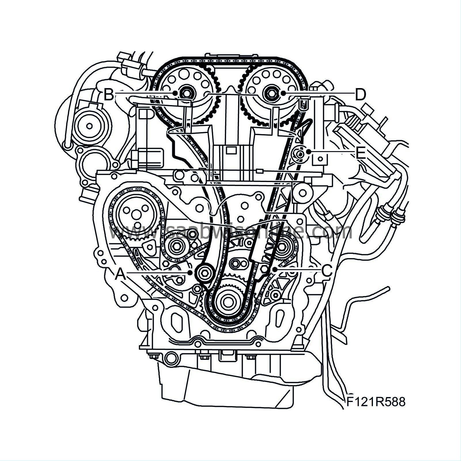
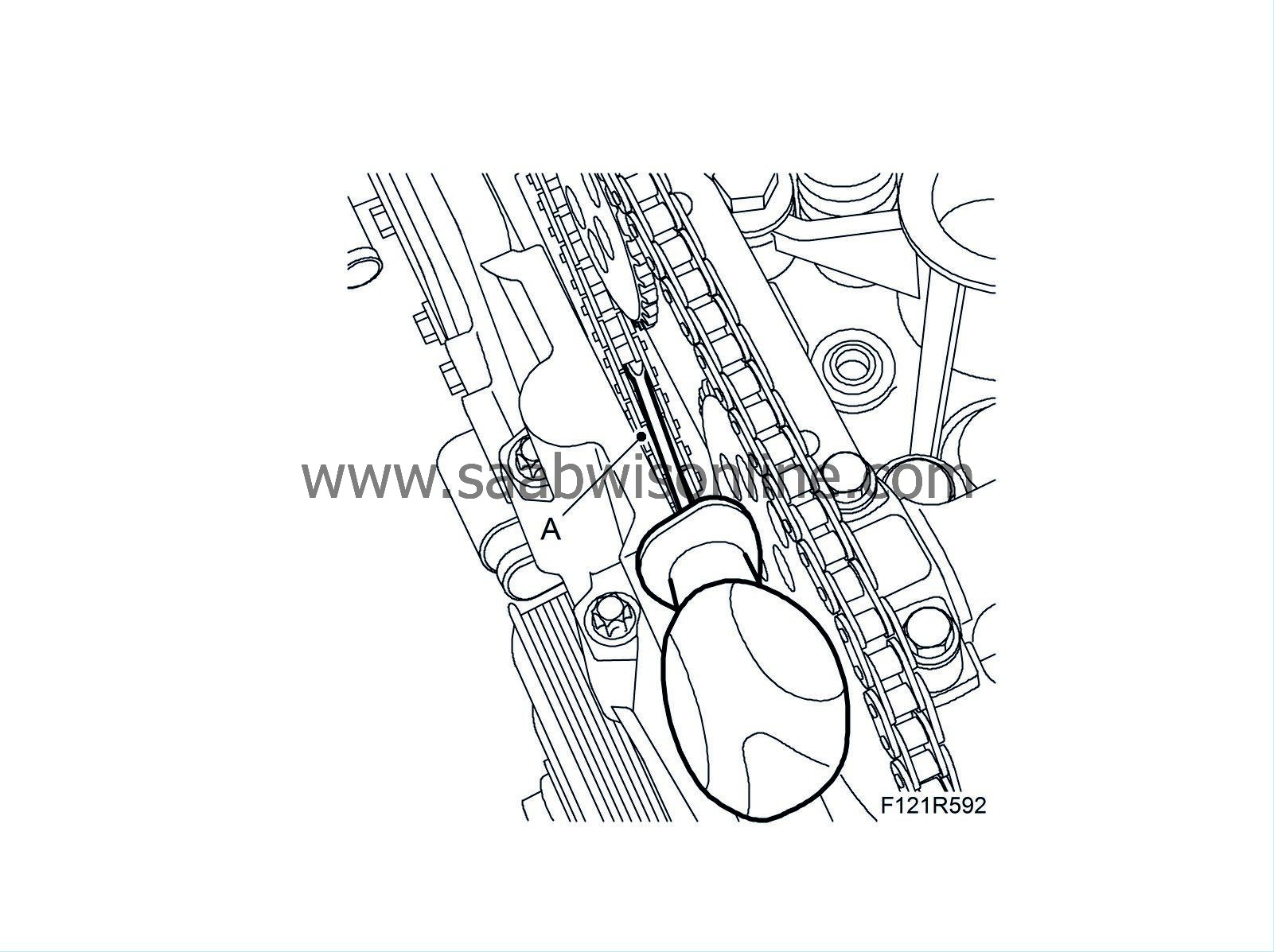
Clean the camshaft and pinion contact surfaces (A) from oil and grease.
|
|
14.
|
Fit the tensioner guide (A).
Tightening torque 10 Nm (7 lbf ft)
|
|
15.
|
Lay the chain on the intake sprocket and lower the chain. Fit the sprocket on the camshaft and tighten the bolt (B).
|
|
16.
|
Fit the chain on the crankshaft sprocket and fit the chain guide. Fit the lower bolt (C).
Tightening torque 10 Nm (7 lbf ft)
|
|
17.
|
Fit the exhaust sprocket and tighten the bolt (D).
|
|
18.
|
Fit the upper bolt (E). Fit the plug on the cylinder head.
|
|
19.
|
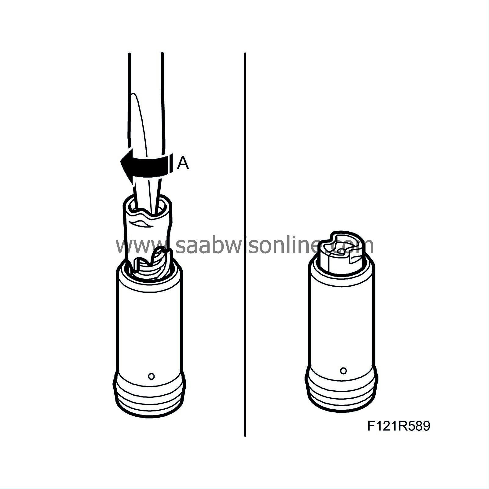
Turn the camshaft drive tensioner clockwise (A) with a screwdriver until it engages in the tensioned position.
|
|
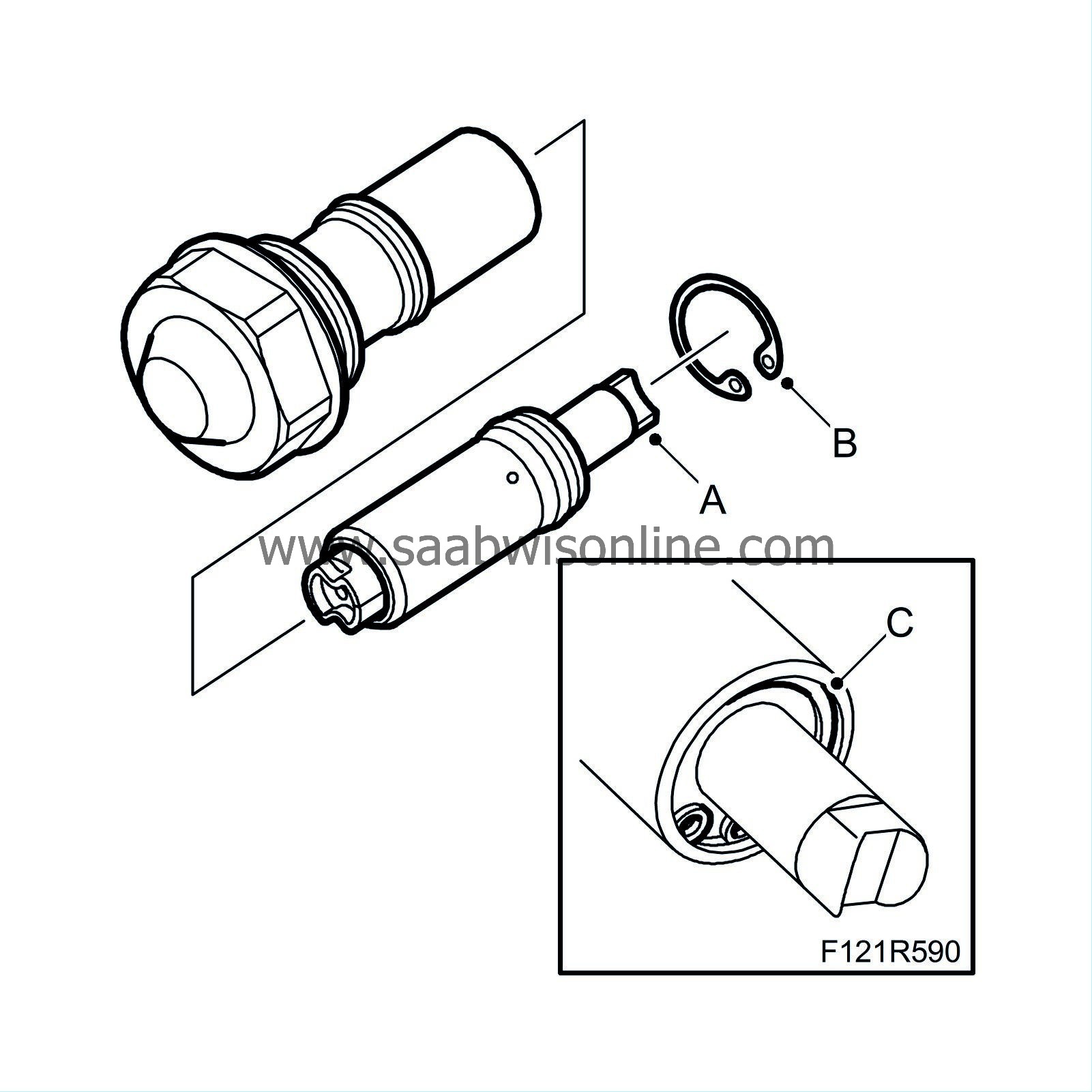
20.
|
Place the plunger (A) in the chain tensioner sleeve. Fit the circlip (B) and check that it is fitted correctly in the groove (C).
|
Note
|
|
Check that the O-ring and gasket are intact. If damaged, replace the chain tensioner assembly.
|
|
|
21.
|
Fit the chain tensioner (A).
Tightening torque 75 Nm (55 lbf ft)
|
|
22.
|
Release/activate the chain tensioner by carefully pressing (A) on the transmission chain or chain guide (as shown). Use a screwdriver. Check that the tensioner releases.
|
|
23.
|
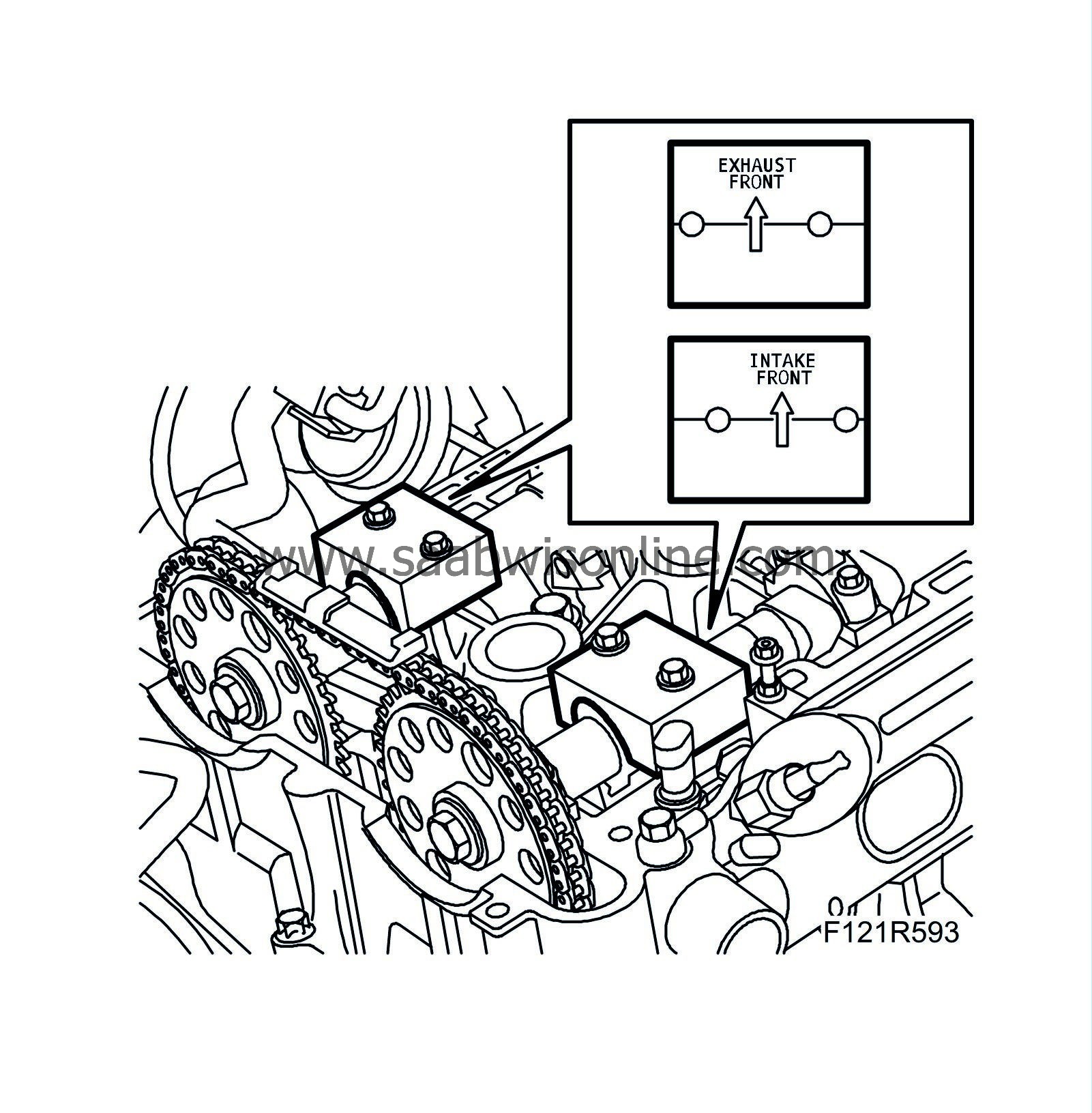
Remove exhaust camshaft and intake camshaft bearing caps No. 2 and No. 7 respectively.
Fit A-48 368 Adjustment tool, camshaft (B207 210 hp) and EN-48366 Adjustment tool, camshaft (B207 150-175 hp) respectively.
Press down the tools with hand force on the camshafts, without tightening the bolts.
Turn the camshaft until the tool aligns with the spanner on the camshaft flats.
Tighten the adjustment tools' bolts.
Tightening torque 10 Nm (7 lbf ft)
|
|
24.
|
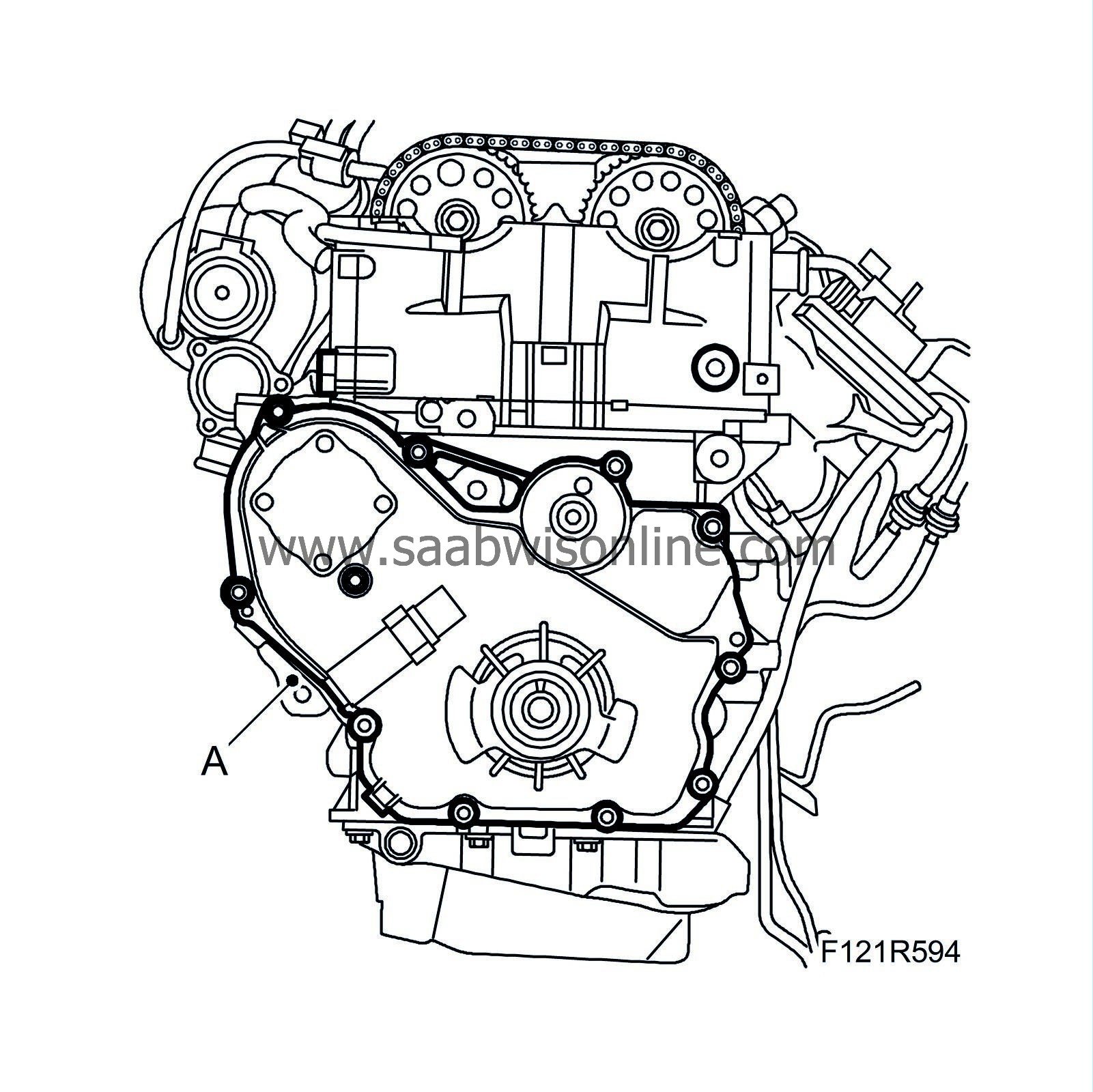
Fit the timing cover (A) with a new gasket.
Tightening torque 20 Nm (15 lbf ft)
|
|
26.
|
Position the fitting tool (B) on the crankshaft. Tighten the sealing ring using the crankshaft pulley bolt until it is flush with the timing cover. Remove the tool.
|
|
28.
|
Check that the markings on the crankshaft pulley and the timing cover are aligned. Tighten the camshaft gears (A) a first time. Use a spanner to grip the camshaft flats.
Tightening torque 30 Nm (22 lbf ft)

|
|
29.
|
Remove the adjustment tools and fit the bearing caps (B).
Tightening torque 8 Nm (6 lbf ft)
|
|
30.
|
Continue to tighten the camshaft gears (C) to the final torque. Use a spanner to grip the camshaft flats.
Tightening torque 85 Nm + 30° (63 lbf ft +30°)
|
|
31.
|
Rotate the crankshaft 2 turns in the direction of engine rotation until the mark on the crankshaft pulley agrees with the mark on the timing cover. Remove the bearing caps and fit EN-48368 Adjustment tool, camshaft (B207 210 hp) and EN-48366 Adjustment tool, camshaft (B207, 150 - 175 hp) again to check that the camshaft setting is correct. Remove the adjustment tools and refit the bearing caps.
Tightening torque 8 Nm (6 lbf ft)
|
|
32.
|
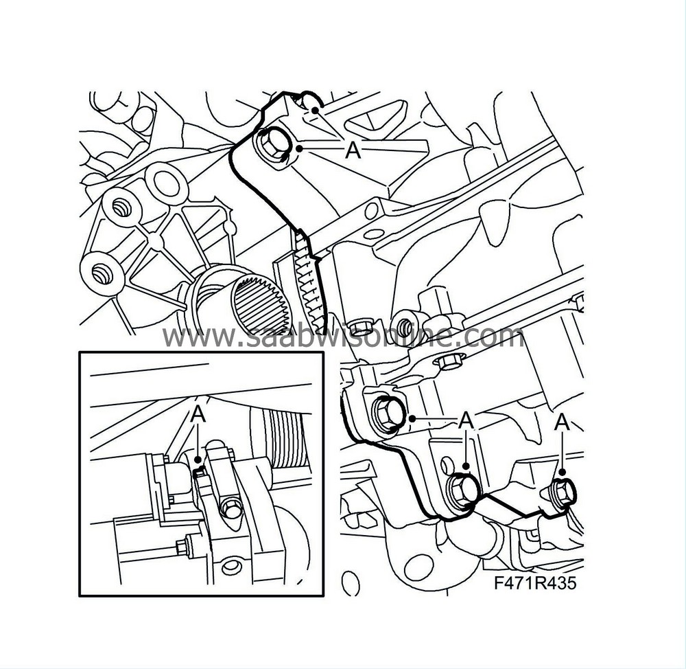
Fit the timing chain's upper guide rail (D).
Tightening torque 10 Nm (7 lbf ft)
|
|
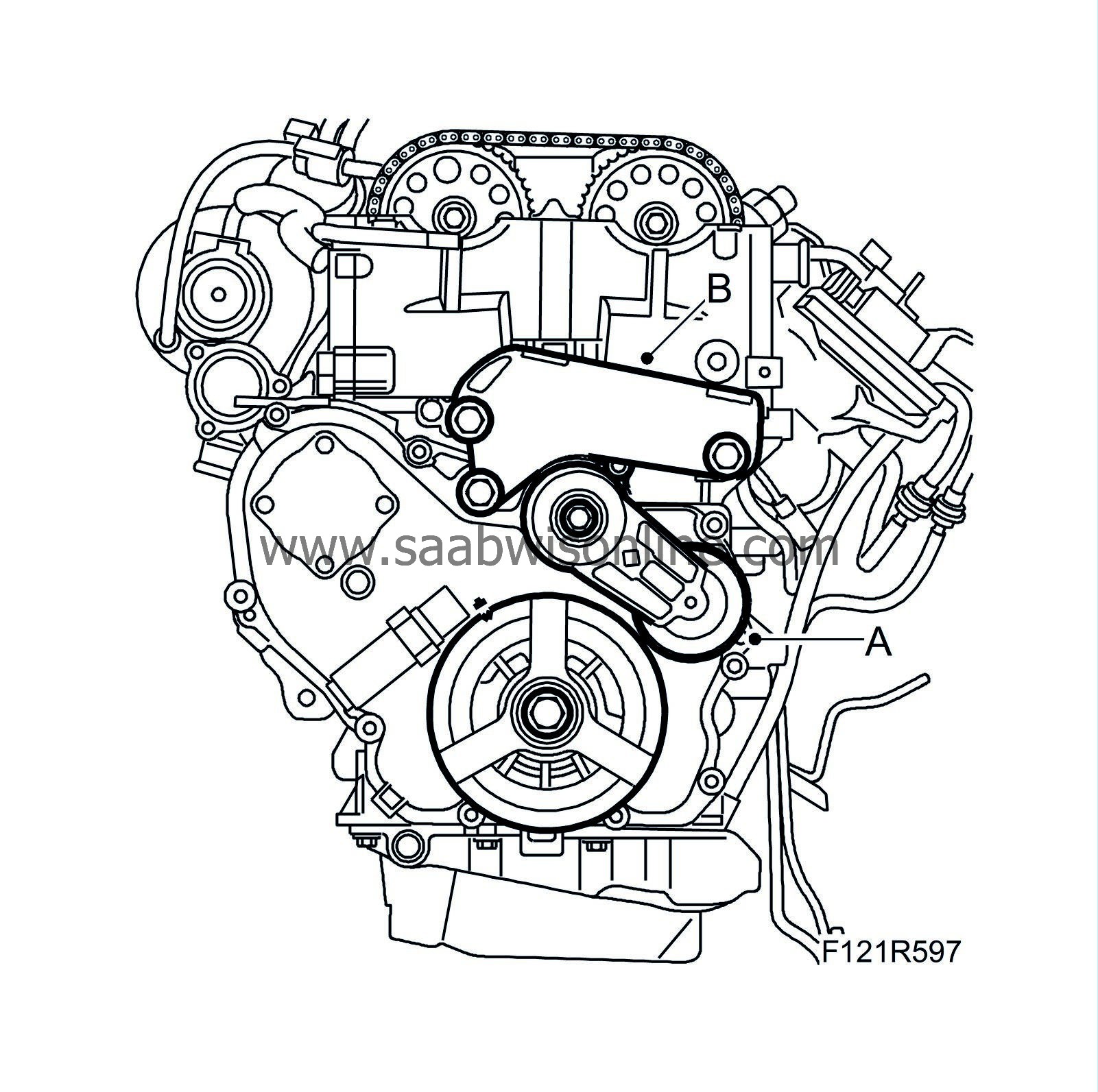
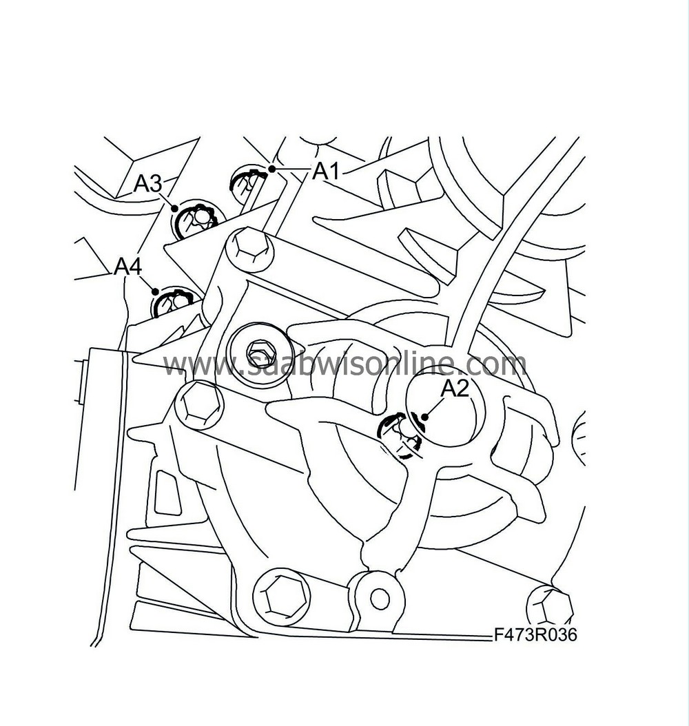
33.
|
Fit the belt tensioner (A).
Tightening torque 50 Nm (37 lbf ft)
|
|
34.
|
Fit the engine mounting bracket (B).
Tightening torque 93 Nm (69 lbf ft)
|
|
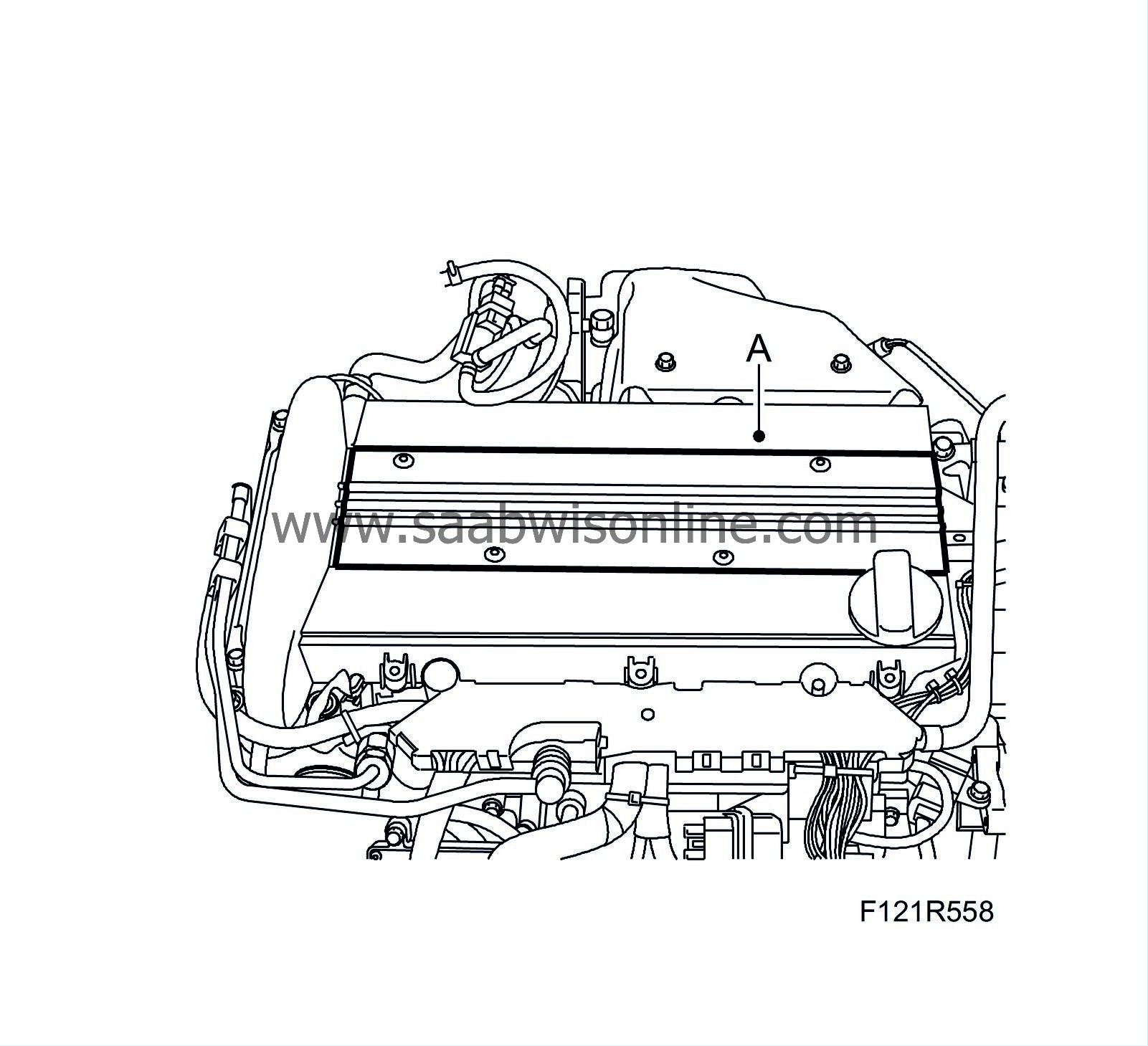
35.
|
Fit the camshaft cover (C).
Tightening torque 10 Nm (7 lbf ft)
|
|
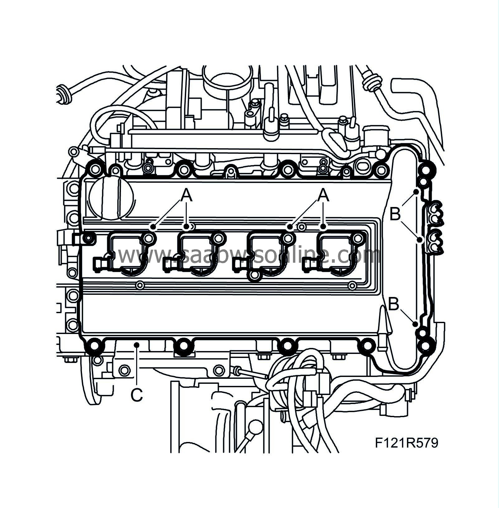
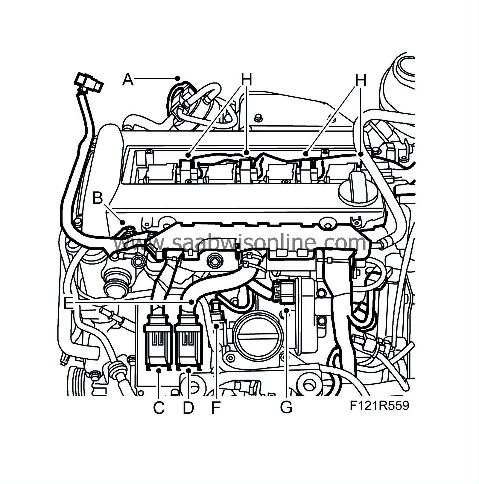
37.
|
Fit the ignition coils (A).
Tightening torque 8 Nm (6 lbf ft)
|
|
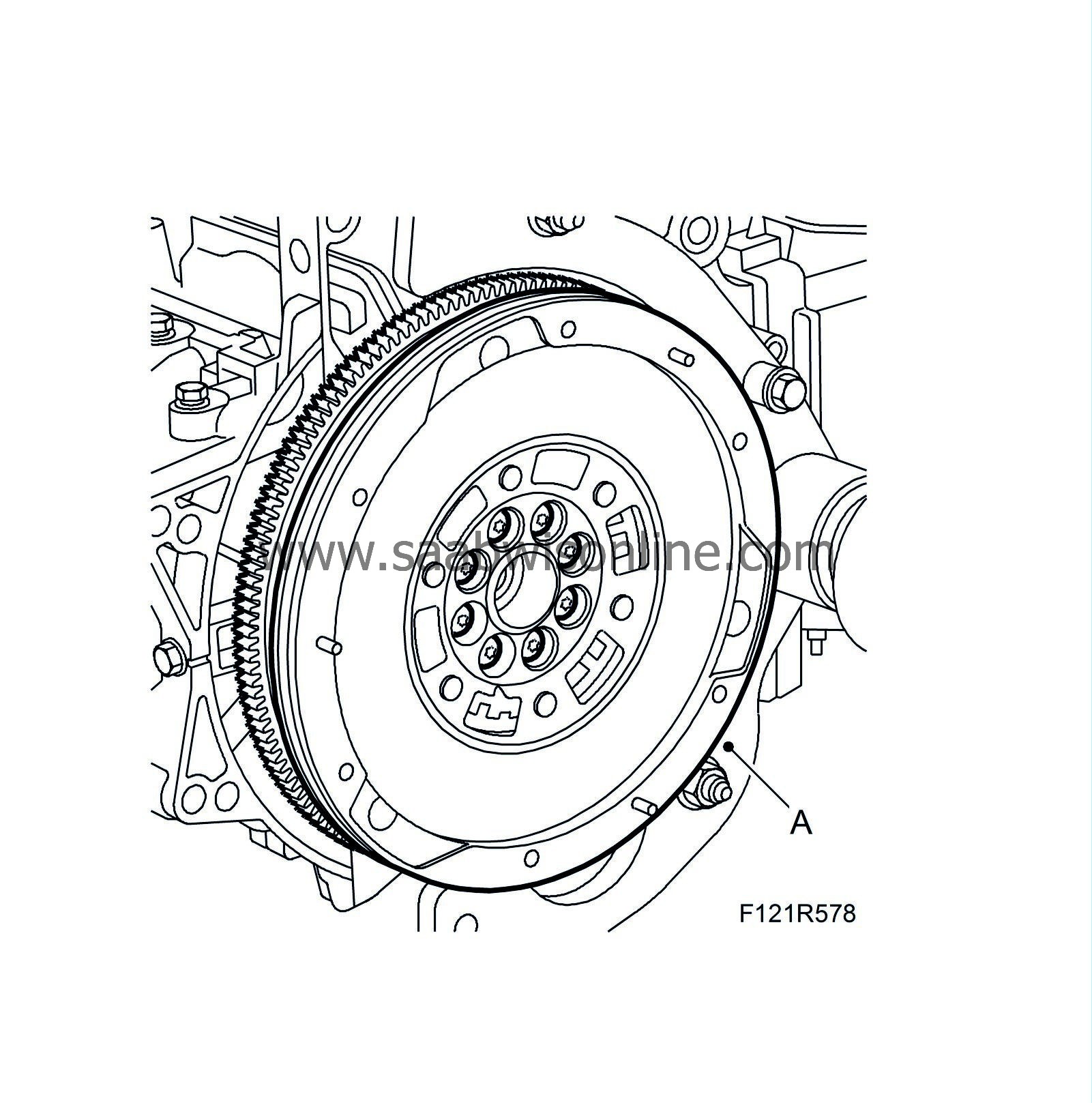
38.
|
Fit
83 94 868 Flywheel locking attachment
. Fit the flywheel (A) with new bolts. Use thread locking adhesive on the bolts. Tighten the bolts alternately.
Tightening torque, solid flywheel 53 Nm + 25° (49 lbf ft + 25°)
Tightening torque, dual mass flywheel 60 Nm +30° (44 lbf ft +30°)
|
|
39.
|
Aut:
Fit the driver plate on the crankshaft.
Tightening torque 53 Nm + 25° (49 lbf ft + 25°)
|
|
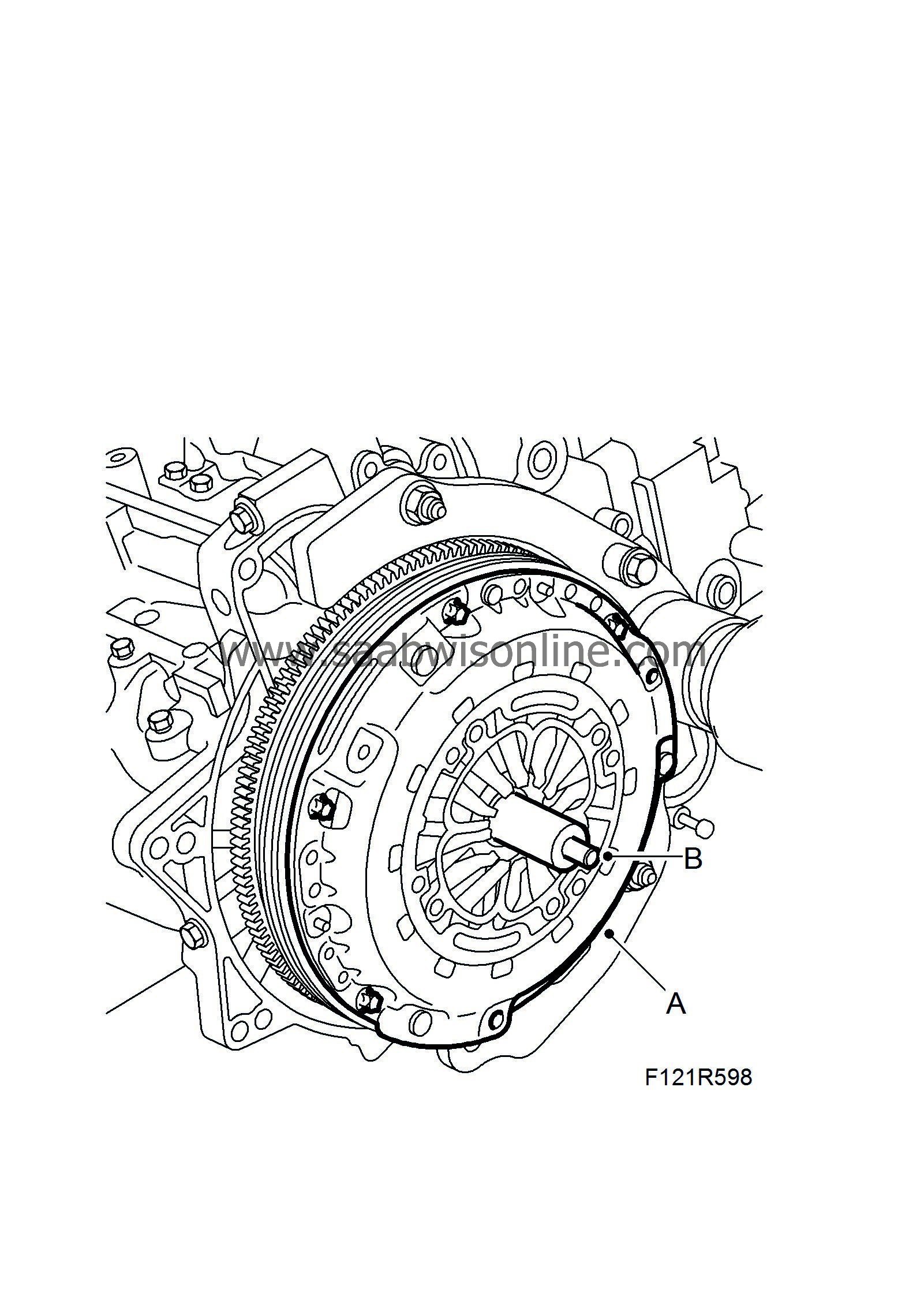
40.
|
Man:
Place the driven plate and pressure plate (A) on the flywheel and fit the bolts without tightening.
Cars with dual mass flywheel:
The convex side of the driven plate must be turned towards the gearbox. Fit the bolts that hold the pressure plate (A) and fit the clutch and driven plate hub.
|
|
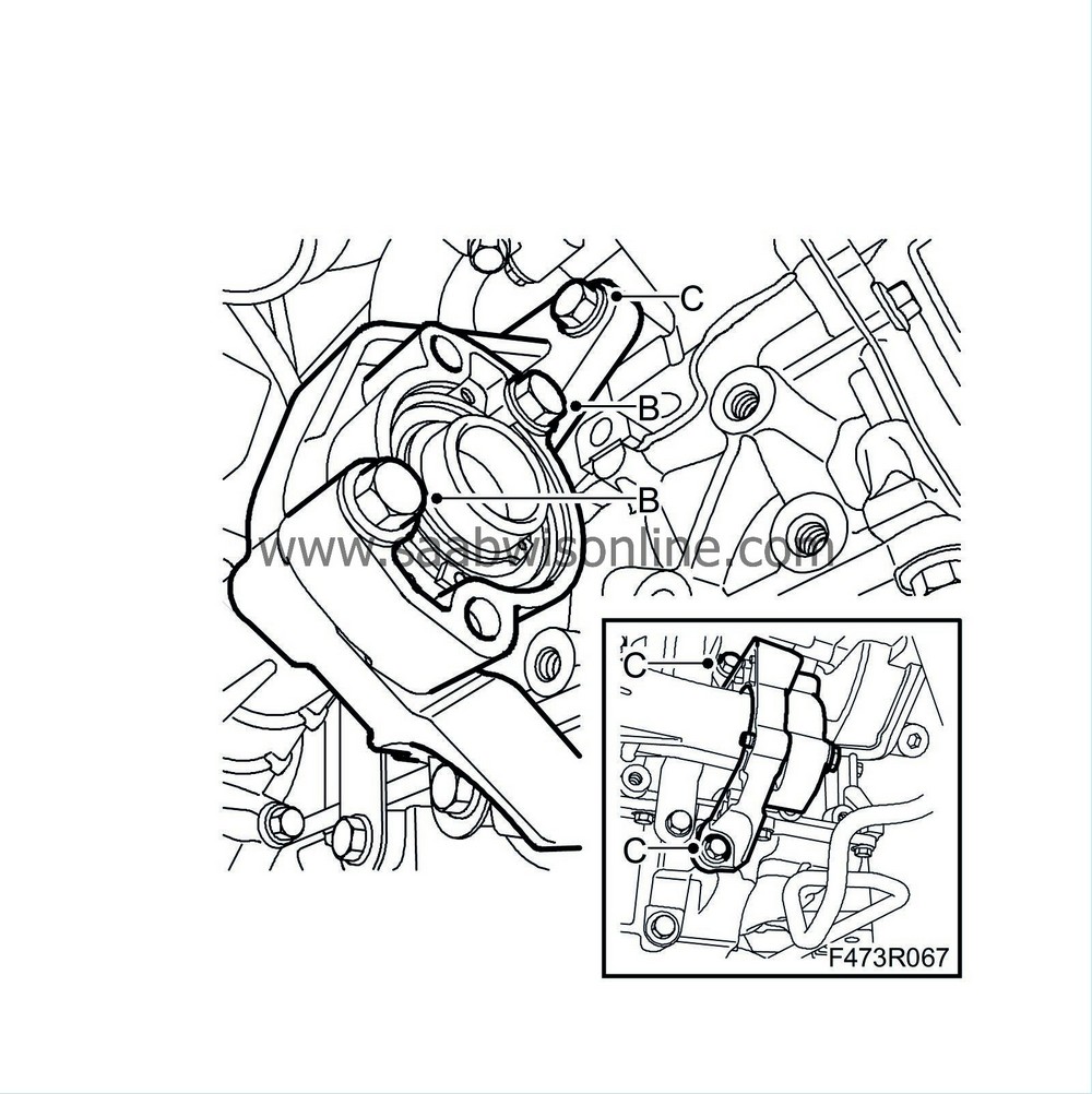
43.
|
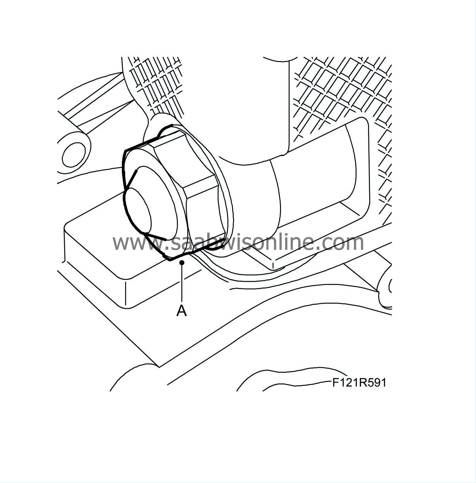
Fit the bolt (C) to the dipstick tube.

|
|
44.
|
Fit the crankshaft position sensor (B).
|
|
45.
|
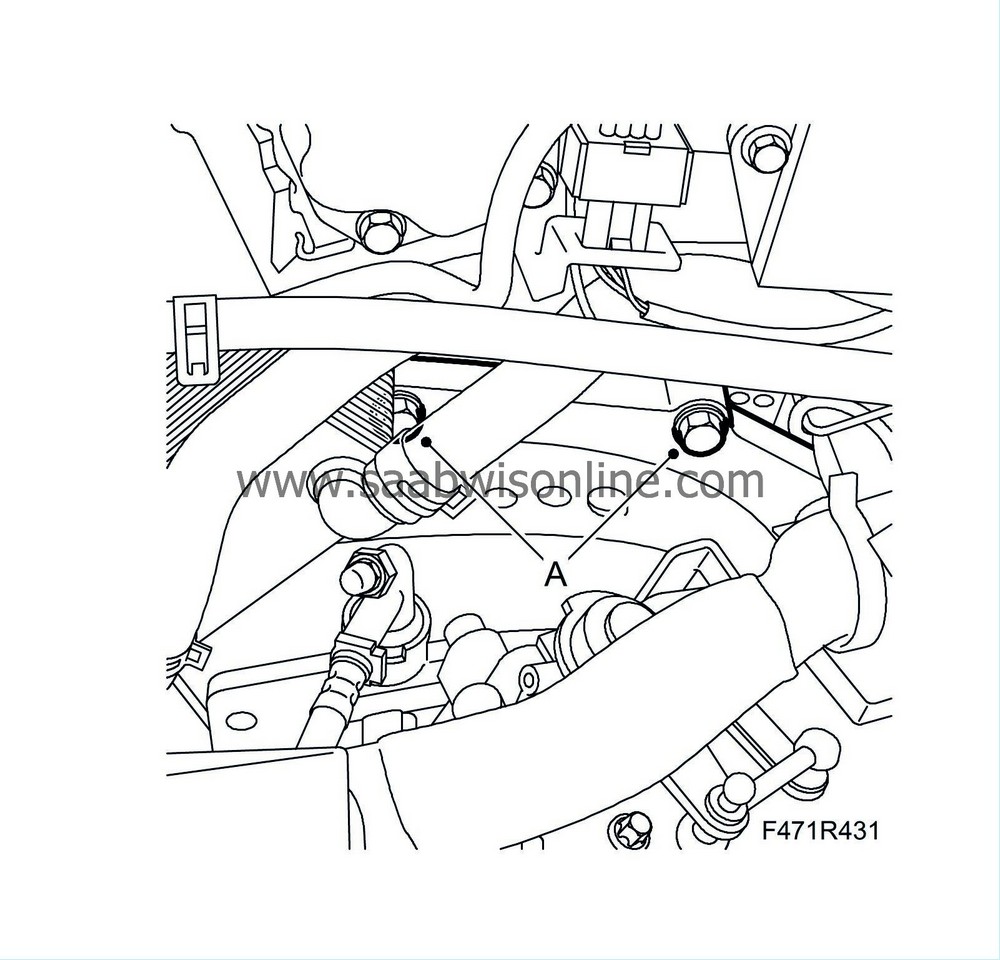
Fit the intake manifold's lower attachment bracket (A).
Tightening torque 22 Nm (16 lbf ft)
|
|
46.
|
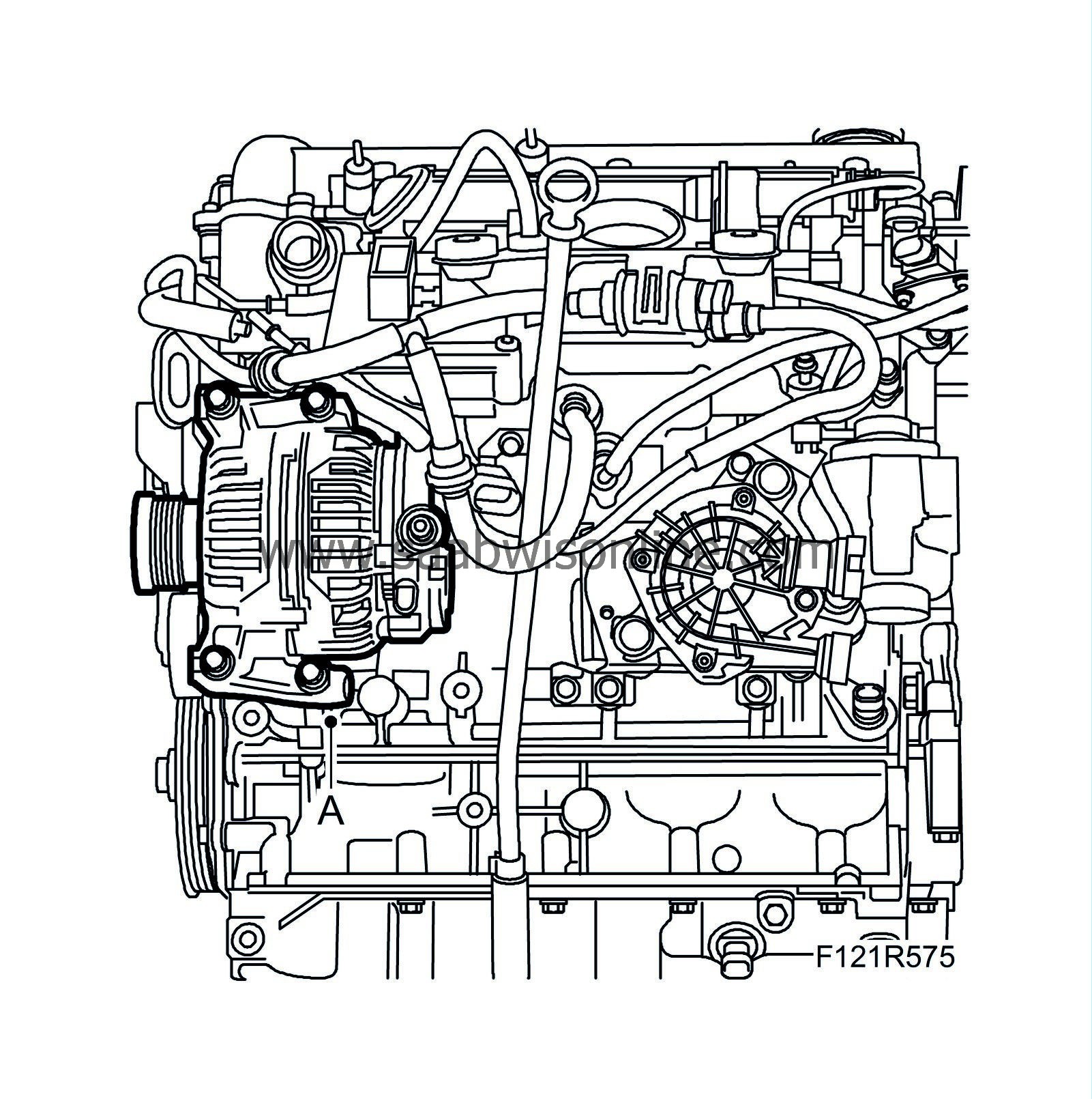
Fit the alternator (A).
Tightening torque 20 Nm (15 lbf ft)
|
|
47.
|
Fit the crankcase ventilation hose (D) to the camshaft cover.
|
|
48.
|
Fit the lower turbocharger attachment bracket (C).
Tightening torque 22 Nm (16 lbf ft)
|
|
49.
|
Fit the turbocharger oil return pipe (B) with a new gasket and O-ring.
Tightening torque 15 Nm (11 lbf ft)
|
|
50.
|
Fit the turbocharger oil delivery pipe (A) with new gaskets.
Tightening torque 28 Nm (21 lbf ft)
|
|
51.
|
Secure the engine with an engine lift.
|
|
52.
|
Lift the engine off the engine stand and lower it carefully onto a pallet. Remove
83 94 751 Holder, engine
from the engine.
|
|
54.
|
Aut:
Remove 87 92 574 Holder that holds the torque converter in place. Press the torque converter toward the driver plate. Fit the plug.
|
|
55.
|
Fit the gearbox upper bolts (A).
Tightening torque 70 Nm (52 lbf ft)
|
|
56.
|
Fit the gearbox lower bolts.
Tightening torque 70 Nm (52 lbf ft)
|
|
57.
|
Fit the transfer case with a new O-ring.
|
|
58.
|
Fit the transfer case (A). Tighten the bolts in the correct order as illustrated.
Tightening torque 110 Nm (81 lbf ft)
|
|
59.
|
Fit the support bracket between the transfer case and the engine carefully in three steps to avoid breakage.
Tightening torque, bolts (B) step 1: 5 Nm (3.7 lbf ft).
Tightening torque, bolts (C) step 2:60 Nm (44 lbf ft).
Tightening torque, bolts (B) step 3:60 Nm (44 lbf ft).
|
|
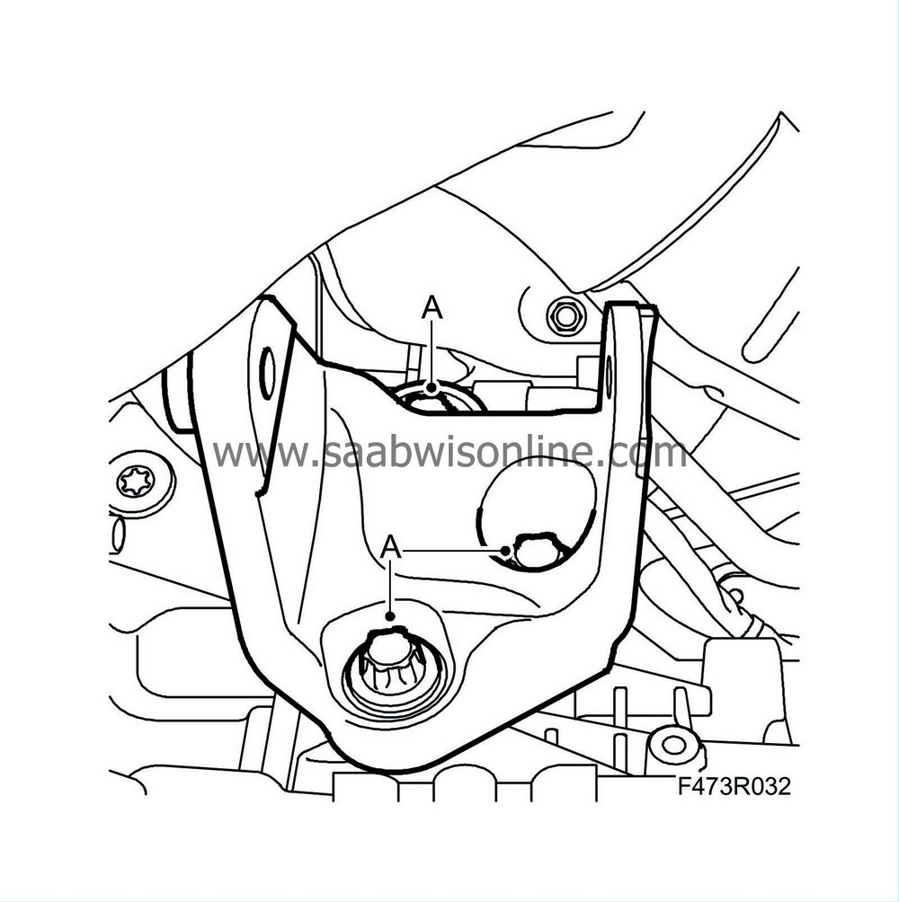
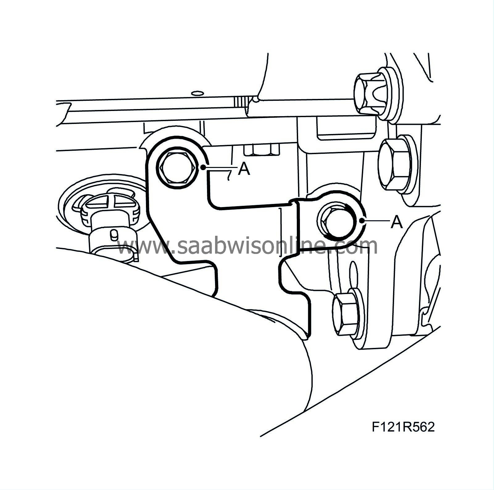
60.
|
Fit the rear torque rod bracket (A).
Tightening torque 80 Nm (59 lbf ft).
|
|
61.
|
Lift the engine up onto the subframe and centre the engine on the subframe using KM 6313 Centring fixture, subframe - engine.
|
|
62.
|
Fit the rear torque rod's bolt.
Tightening torque 80 Nm (59 lbf ft).
|
|
63.
|
Fit the front torque rod's bolt.
Tightening torque: 60 Nm +90° (44 lbf ft + 90°)
|
|
64.
|
Remove the engine lift.
|
|
66.
|
Aut:
Apply thread locking adhesive to the bolts (A) holding the torque converter to the driver plate.
|
Note
|
|
Use the original bolts with associated washers. The torque converter will be ruined if the bolts that are used that are too long.
|
|
|
67.
|
Fit the 6 bolts without tightening them.
|
|
68.
|
Turn the engine clockwise with the pulley and tighten the bolts (A) when all are in place.
Tightening torque 60 Nm (44 lbf ft)
|
|
69.
|
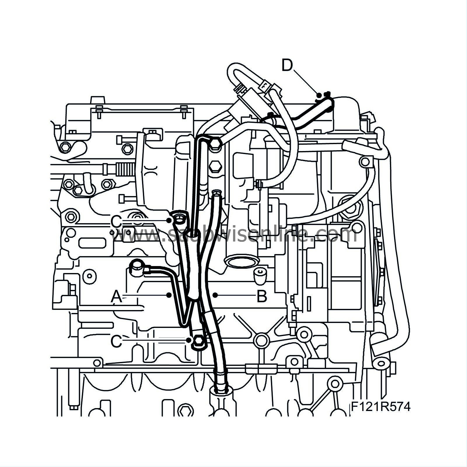
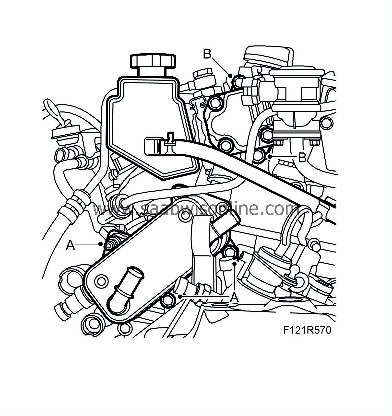
Fit the power steering pump (B) to the cylinder head and replace the gasket.
Tightening torque 22 Nm (16 lbf ft)
|
|
70.
|
Fit the water-cooled oil cooler (A) with new gaskets.
Tightening torque 22 Nm (16 lbf ft)
|
|
71.
|
Fit the starter motor (A).
Tightening torque 47 Nm (35 lbf ft)

|
|
72.
|
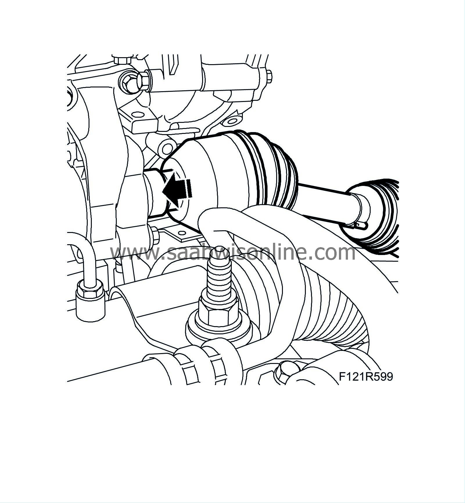
Fit the drive shaft in the intermediate shaft splines. Lubricate the shaft splines with
90 513 210 Universal paste
. Make sure the seal against the intermediate shaft has been fitted.
|
|
73.
|
Fit the thermostat housing (B) and pipe (C) with new O-rings. Lubricate the pipe's O-ring sparingly with vaseline.
Tightening torque 10 Nm (7 lbf ft)

|
|
74.
|
Fit the turbocharger coolant pipe (A). Fit the banjo screws with new gaskets.
Tightening torque M12, 28 Nm (21 lbf ft)
Tightening torque M14, 40 Nm (30 lbf ft)
|
|
75.
|
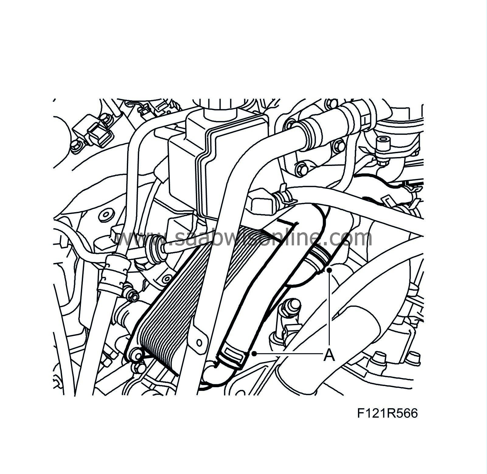
Fit the hoses (A) to the oil cooler. Check that the oil cooler hose clips do not rest against the lower radiator hose. Adjust if necessary.
|
|
76.
|
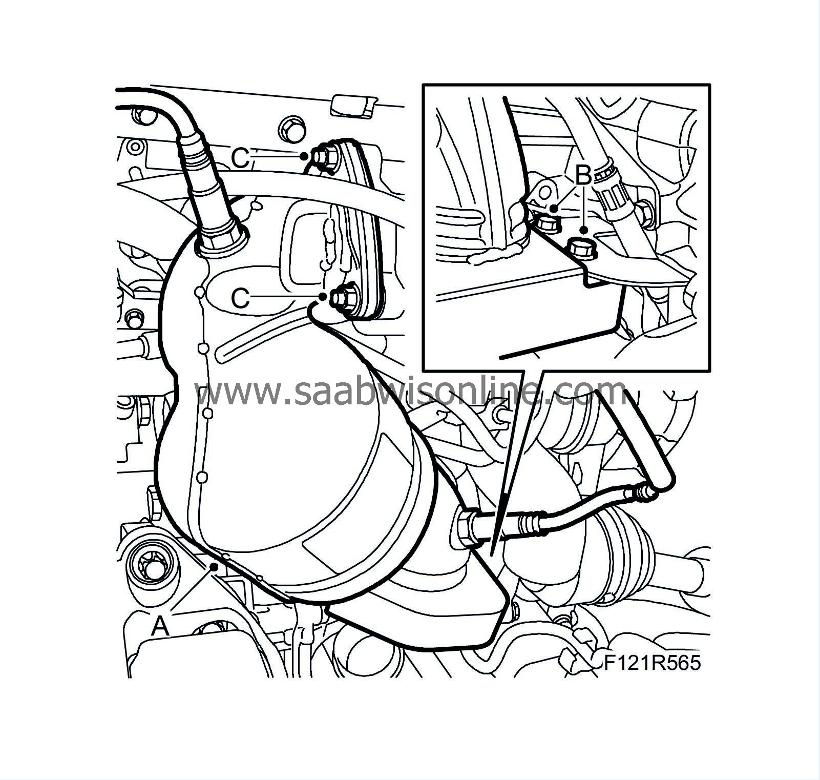
Fit the catalytic converter (A) with new nuts (C).
Tightening torque 25 Nm (18 lbf ft)
|
|
77.
|
Fit the bracket (B) to the catalytic converter and oil pan.
|
|
78.
|
Press the oxygen sensor connectors firmly into place in the bracket.
|
|
79.
|
Fit the turbocharger heat shield (A).
Tightening torque 10 Nm (7 lbf ft)

|
|
80.
|
Fit the charge air pipe (B) and heat shield (A).

|
|
81.
|
Fit the bolts (A) that hold the lower charge air pipe.
Tightening torque 22 Nm (30 lbf ft)
|
Important
|
|
Take care when plugging in the connector so as not to damage or press out the pins/sleeves in the connector. For further information regarding connectors, refer to
Connectors, handling and inspection
.
|
|
|
|
|
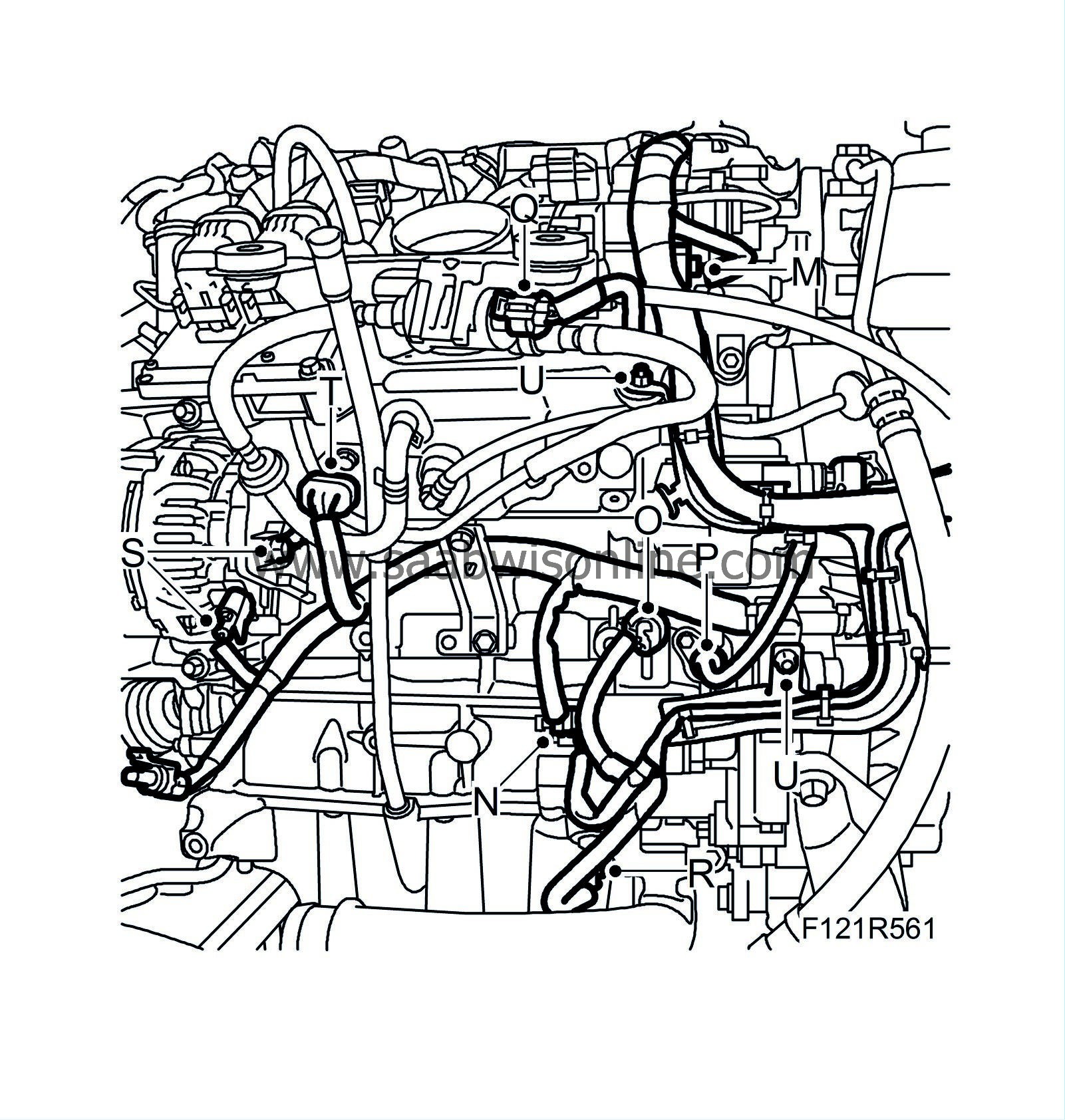
82.
|
Position the engine wiring harness and plug in the following connectors:
|
|
|
•
|
Plug in the connector to the charge air solenoid valve (A).
|
|
|
•
|
Plug in the connector to the coolant temperature sensor (B).
|
|
|
•
|
Plug in the engine control module connector (C).
|
|
|
•
|
Plug in the engine control module connector (D).
|
|
|
•
|
Fit grounding point G7 (E).
|
|
|
•
|
Plug in the charge air bypass valve connector (F).
|
|
|
•
|
Plug in the throttle body connector (G).
|
|
|
•
|
Plug in the connector (H) for the 4 ignition coils.
|
|
|
•
|
Plug in the connector to the ionisation detection module (I).

|
|
|
•
|
Plug in the connector to the front oxygen sensor (J).
|
|
|
•
|
Plug in the connector to the rear oxygen sensor (K).
|
|
|
•
|
Plug in the connector to the power steering pump's pressure sensor (L).
|
|
|
•
|
Plug in the connector to the intake manifold pressure sensor (M).
|
|
|
•
|
Fit the starter motor contacts (N).
|
|
|
•
|
Fit the oil pressure switch (O).
|
|
|
•
|
Plug in the connector to the crankshaft position sensor (P).
|
|
|
•
|
Plug in the EVAP canister purge valve connector (Q).
|
|
|
•
|
Plug in the oil level sensor connector (R).
|
|
|
•
|
Plug in the alternator connector (S).
|
|
|
•
|
Plug in connector H8-9 (T).
|
|
|
•
|
Fit the wiring harness retaining bolts (U).
|
|
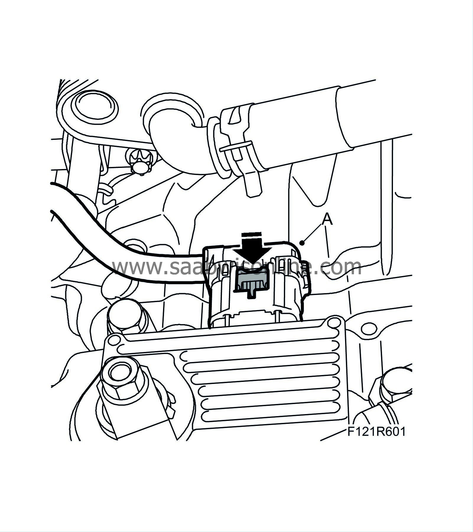
83.
|
Fit the connector (A) to the control module.
|
|
84.
|
Fit the cover (A) to the spark plugs.
|


