PRE-RELEASE
Detailed description
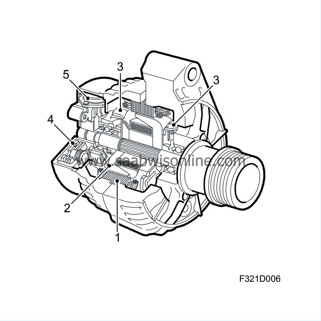
| Detailed description |
| 1. |
Stator
|
|
| 2. |
Rotor with slip rings
|
|
| 3. |
Integral fans
|
|
| 4. |
Rectifier
|
|
| 5. |
Voltage regulator
|
|
The generator is driven by the engine with a poly-V belt from the crankshaft pulley. The gear ratio between the engine and generator is shown for each generator in the technical data.
Cars with 4-cylinder petrol engine
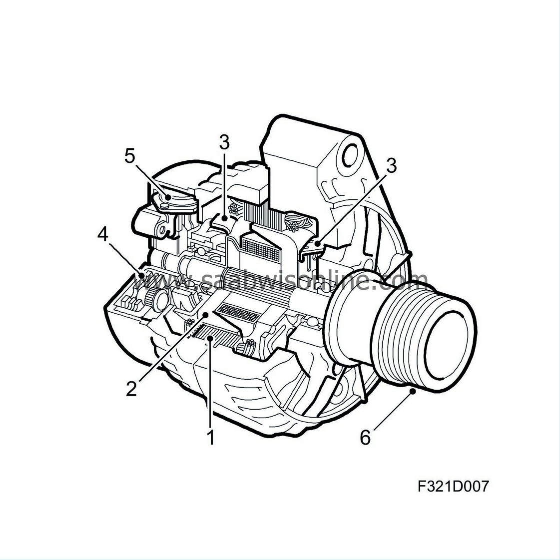
The generator is of the AC type with integral charge regulator. The generator is driven by the engine via a poly-V belt from the crankshaft pulley. Because of the variations in rotation which occur between the engine cycles, a freewheel function is introduced in the pulley which gives a more even rotation for the belt cycle. This in turn results in a longer service life of the poly-V belt.
| 1. |
Stator
|
|
| 2. |
Rotor with slip rings
|
|
| 3. |
Integral fans
|
|
| 4. |
Rectifier
|
|
| 5. |
Voltage regulator
|
|
| 6. |
Pulley with freewheel function
|
|
| Stator |
The stator is fixed and consists of plates with individually insulated grooves compressed together to a plate package. The stator winding's wave shaped coils are located in the grooves. They are delta connected at 120°, giving three-phase alternating current that is led directly to the rectifier.
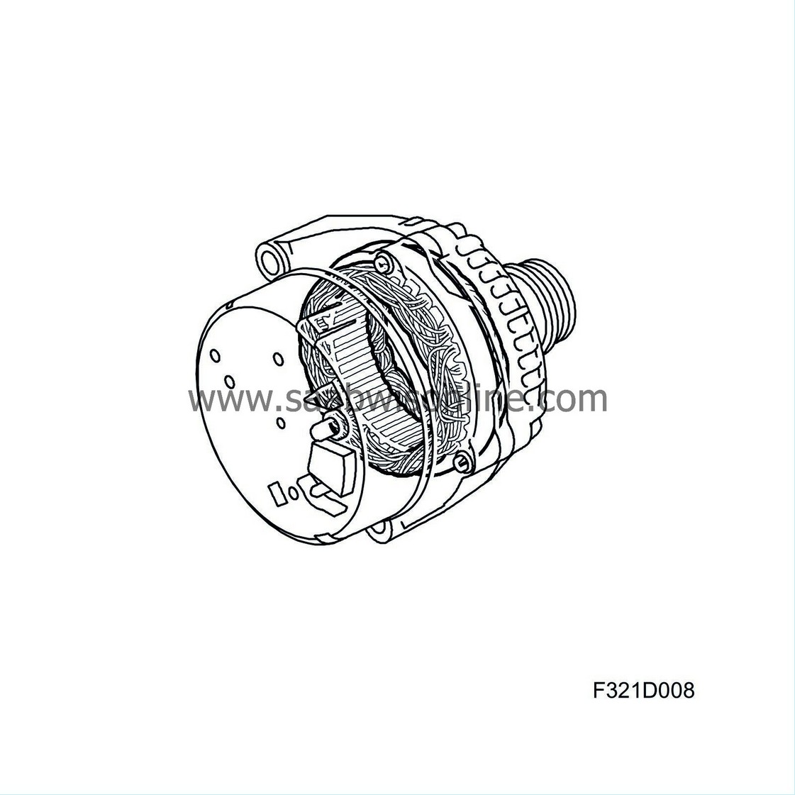
| Rotor with slip rings |
The rotor consists of two halves (claw poles) which engage with each other. The halves are pressed onto the rotor shaft and there are 12 claws on the rotor, i.e. 12 poles. One half has six north poles and the other half six south poles. Between the claw pole halves are magnetisation windings attached to the rotor shaft. The magnetisation windings consist of a circular coil surrounded by the claw poles. Between the claws, which rest on the slip rings, a magnetisation voltage is applied from the regulator.
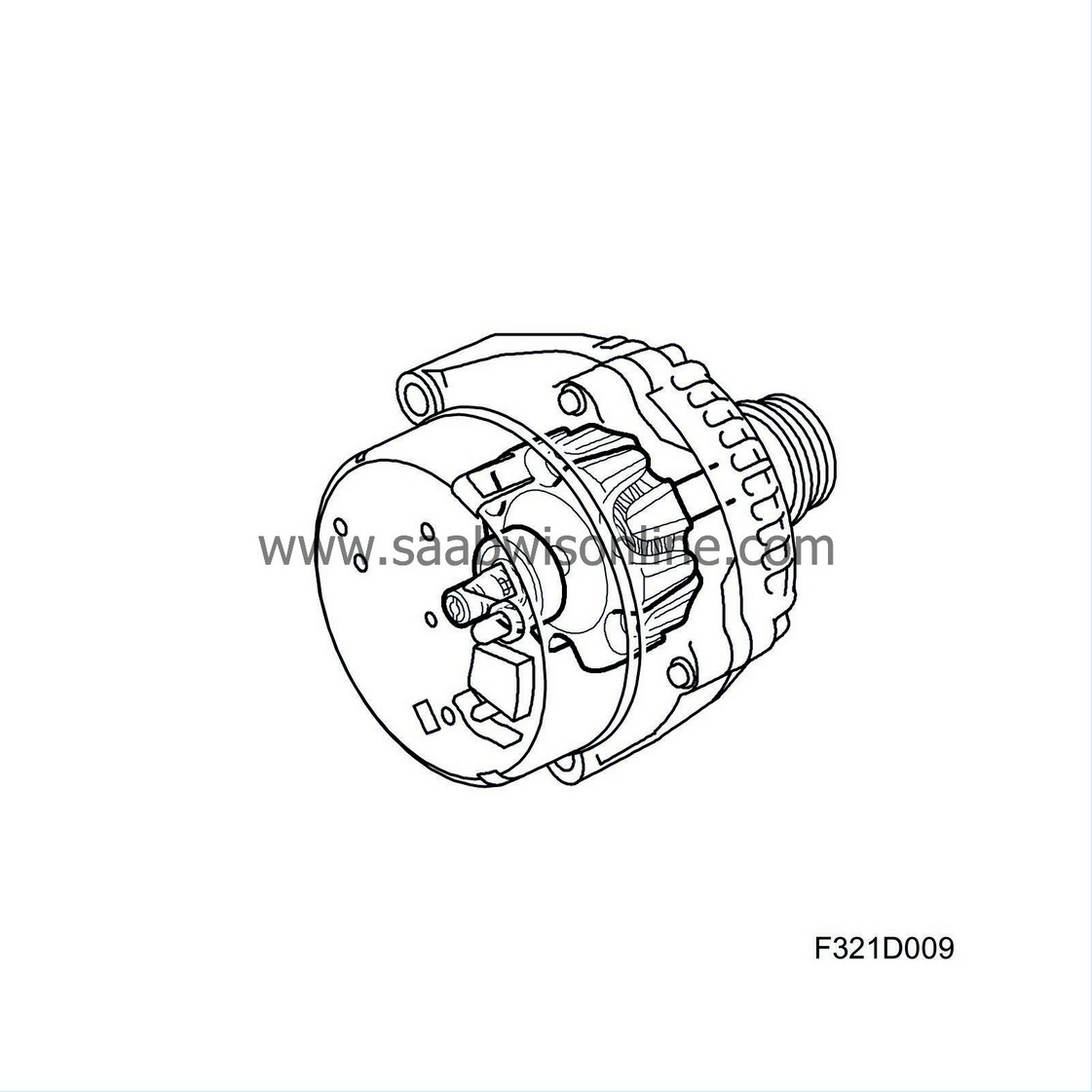
| Integral fans |
The heat developed in the generator during operation can cause damage to the generator. The generator has two integral fans to dissipate the heat. The fans are driven by the generator rotor shaft.
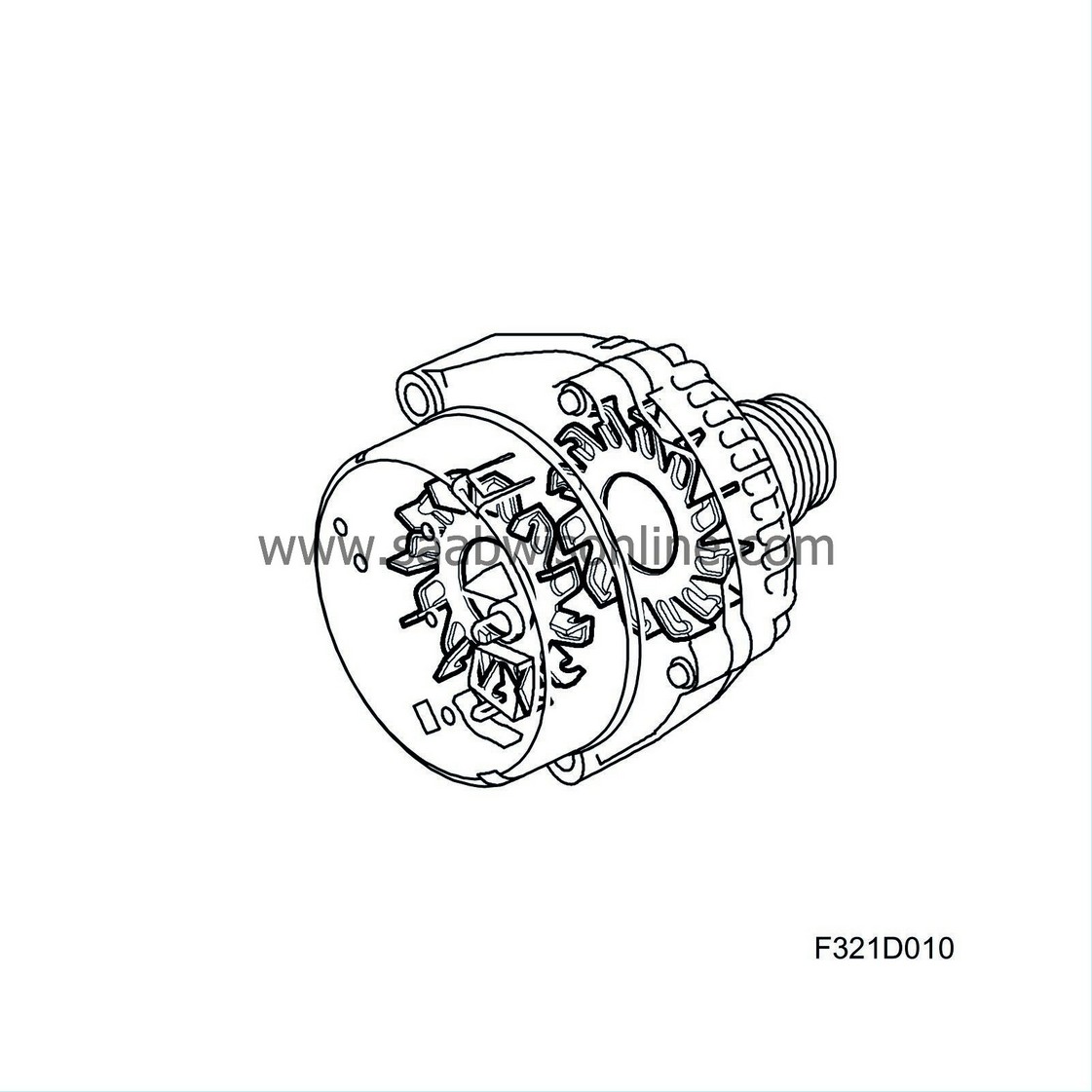
| Rectifier |
The current produced by the generator's stator winding must be converted to direct current before it can be used in the car's electrical system. The current is converted by means of 6 Zener diodes, 2 per phase winding.
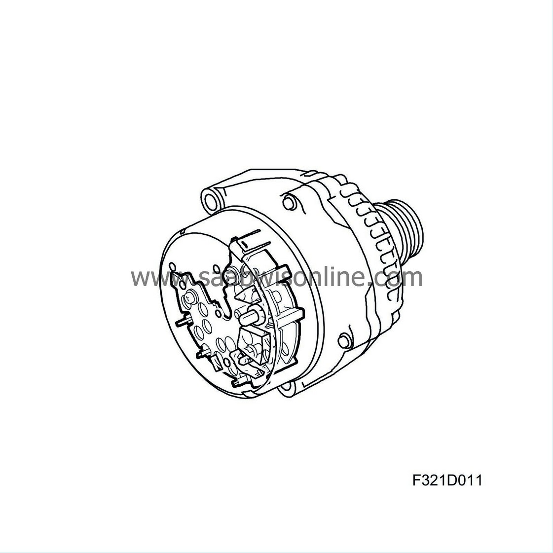
| Voltage regulator |
The purpose of the regulator is to keep the generator voltage constant over the entire engine speed range, irrespective of the generator load and rotation speed. If the generated voltage exceeds the specified nominal value (approx. 14V), depending on load, the regulator lowers the magnetisation flow. The generator magnetisation diminishes and the voltage from the stator windings drops. When the voltage has dropped below the nominal value (approx. 14V), the magnetisation flow increases and hence the generator voltage rises until the nominal voltage is again exceeded. This process is repeated continuously.

| Pulley with freewheel function, 4-cylinder petrol engine |
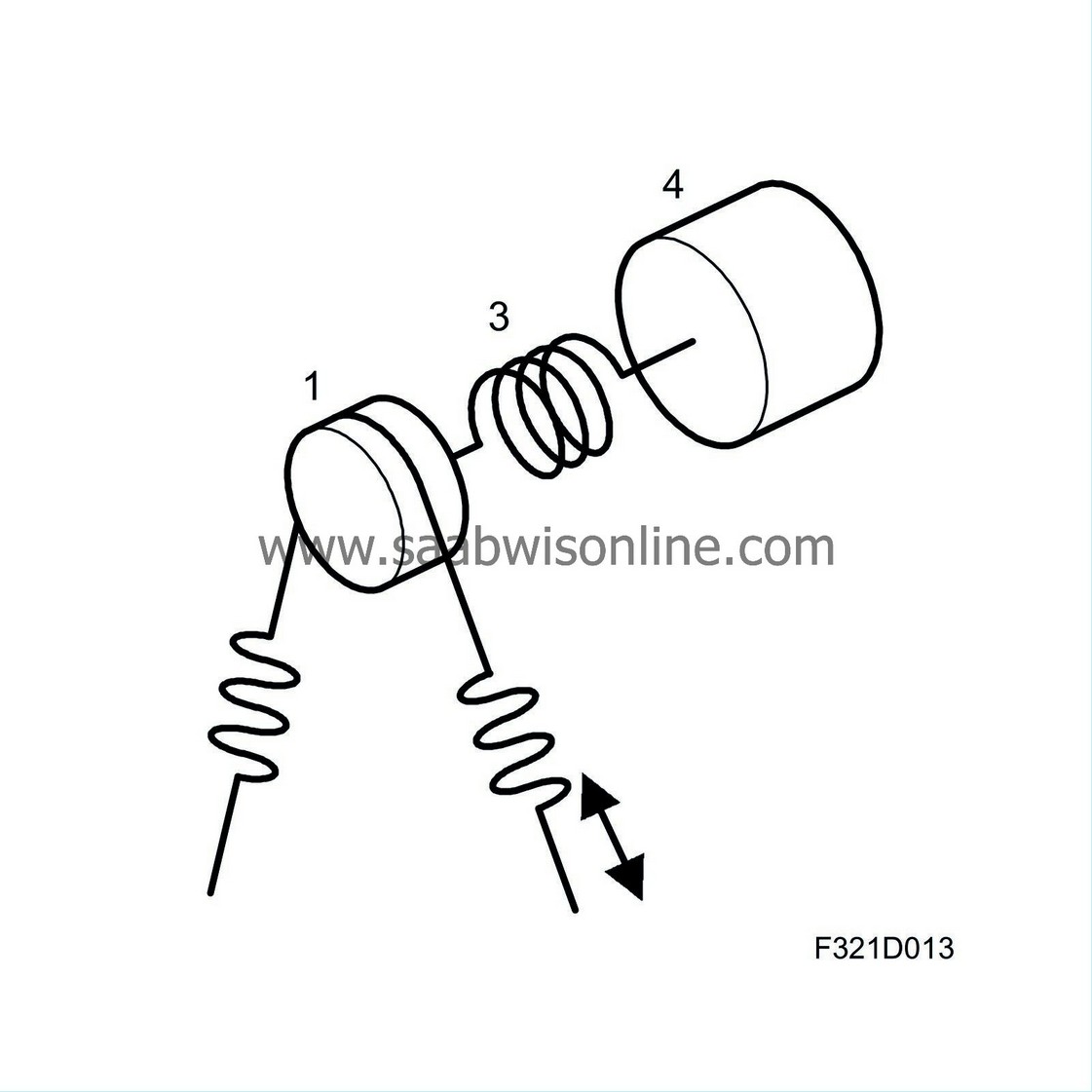
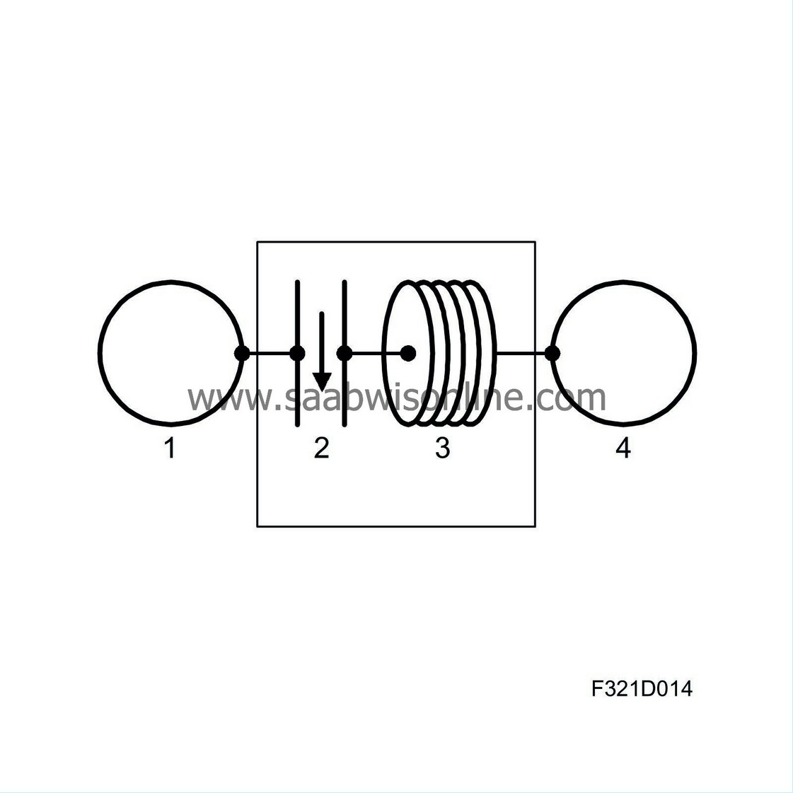
| 1. |
Belt pulley
|
|
| 2. |
Freewheel
|
|
| 3. |
Vibration damper
|
|
| 4. |
Alternator
|
|
The engine speed drops slightly between power strokes, which means that the rotation of the generator will be inhibited by the engine. To stop this happening and attain a smoother running of the belt circuit with less strain on the multigroove belt, the generator is fitted with a freewheel integrated in the pulley. The pulley freewheel function will extend the service life of the multigroove belt. When the engine speed drops lower than the generator speed between power strokes, the freewheel will disengage the generator from the belt circuit. When the engine speed is higher than the generator speed, the freewheel will lock and drive the generator.
| Internal circuitry |
To convert the AC voltage produced by the stator windings into DC voltage, 6 Zener diodes are used. The stator windings form three phases and are delta-coupled.
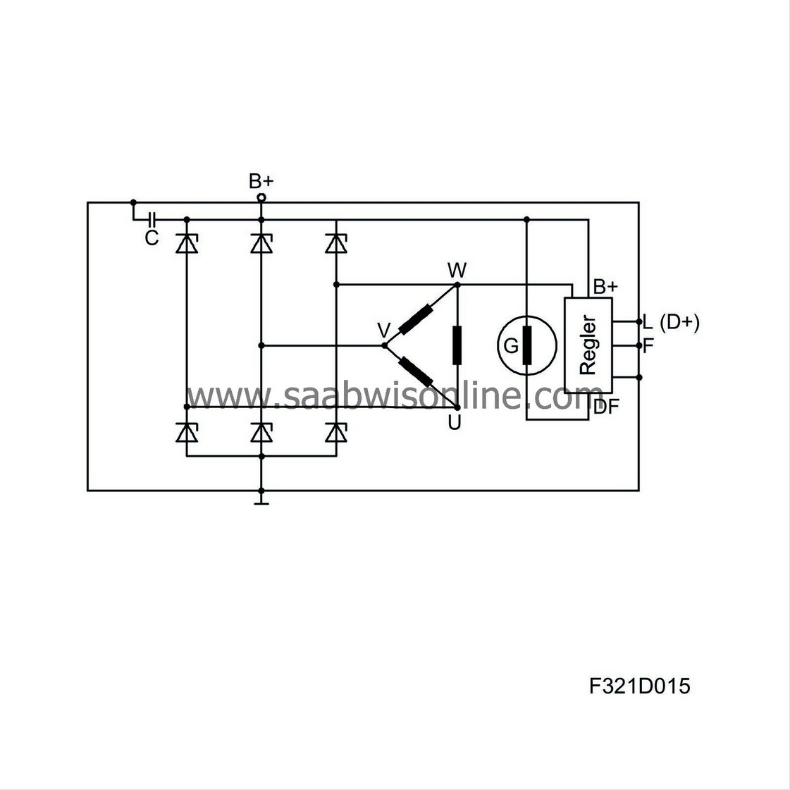
The magnetisation voltage comes from the engine control module when the engine starts, which means that the generator begins to charge. When the generator charges, the magnetisation voltage comes from the B+ connection. This means that no separate magnetisation diodes are required.
The 6 rectifier diodes are bridge-coupled. The diodes are pressed into a diode holder. Depending on polarity, the diode holder is either isolated from the casting or directly connected to it. The magnetisation winding sits on the rotor which is designed with pole claws. Every other claw serves as a north pole and every other claw as a south pole. The magnetisation winding ends are connected to slip rings via which the magnetisation current is supplied.
| Generator, description of operation |
When the engine starts, the engine control module (ECM) sends a signal to the generator connection L. The generator connection L is coupled to the magnetisation winding, which means that the generator begins to charge. To maintain the charge, the engine control module continuously sends out a signal to connection L.
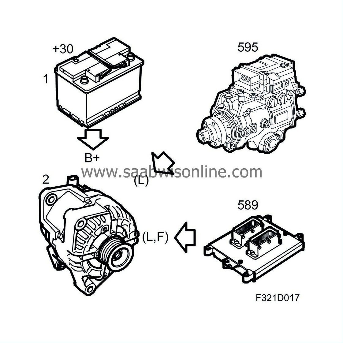
When the rotor in the generator rotates, the magnetic field around the rotor will also rotate and thereby generate an AC voltage in the stator winding. This AC voltage is rectified when it passes the diodes and is then supplied to the car's electrical system via B+. The voltage obtained from the stator winding also passes to the voltage regulator and affects its regulating function. When the voltage exceeds the nominal value (approx. 14V), the voltage regulator will reduce the current through the magnetisation winding. The magnitude of the magnetic field will be reduced, as will the AC voltage generated in the stator winding. When the voltage has dropped below the nominal value, the magnetisation current will increase again, the magnetic field will increase and thereby the charge.
If the engine idle speed falls below the programmed speed, the signal from the engine control module to the connection L is broken. This means that the generator does not receive any magnetisation and does not charge. The engine load is reduced and the risk of stalling avoided.
Connection L is also the diagnostic lead from the generator to the engine control module. If the generator does not charge, an indicator will be displayed on SID and the engine control module will generate a diagnostic trouble code.
Generator connection F in cars with petrol engine B207 or B284 provides information to the engine control module regarding generator load, i.e. how much it is charging, so that the engine management system can correct engine torque and thereby prevent engine speed to change due to different generator loads. Generator connection F is not used in cars with diesel engine or petrol engine Z18XE.
| Warning indicator for charging |
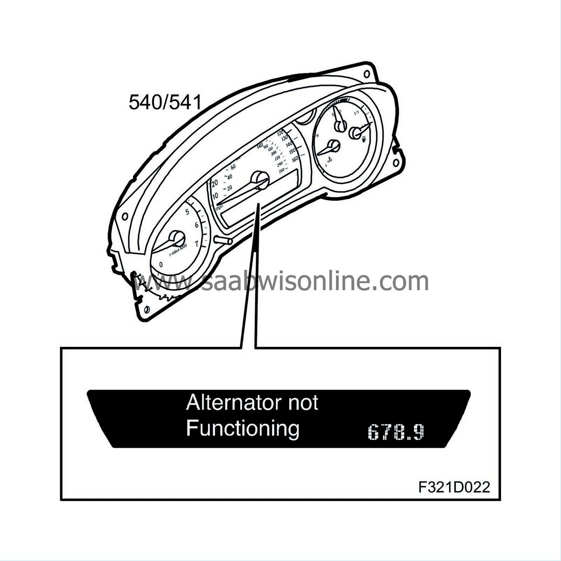
The charge warning indicator advises the driver whether or not the generator is charging. If the generator is not charging then a symbol is shown as well as a warning text in the SID. When no warning message is shown, the generator is charging. Information on the generator's charging status is sent via a cable to the engine control module. The MIU receives information via a bus message from the engine control module as to whether or not the generator is charging. A warning indicator is shown in the SID. When the ignition is on and the engine is not running there is no warning message shown in the SID. A diagnostic trouble code is generated in the engine control module when charging is not working.
| Battery |
The terminal voltage of the battery is 12V and the capacity is dependent on the engine variant. The battery delivers current to the starter motor for starting the engine and supplies other power consumers with current while the engine is not running. The positive battery terminal is connected to the starter motor and to the main fuse box in the engine bay and its negative terminal is connected to the body and the engine.
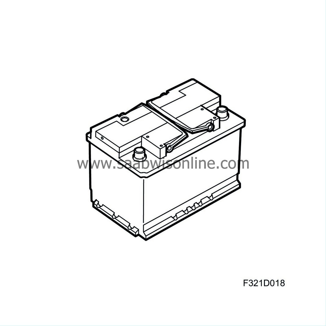
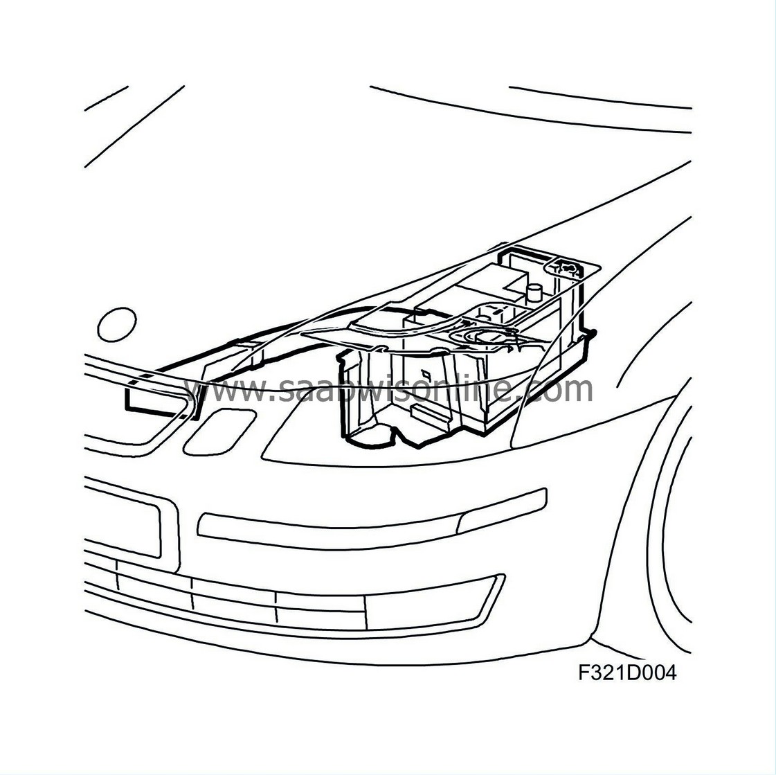
The battery is located on the left-hand side of the engine bay. On some variance, it is contained in a battery cover to reduce heating. An air duct takes in air via the car's grille. The air from the air duct passes through the battery cover and consequently cools down the battery.
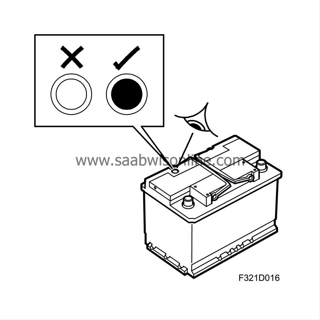
The battery electrolyte cannot be topped up. The battery electrolyte level is indicated by an indicator point on the top of the battery. If the indicator is dark, the level is OK. On low level the indicator is light and the battery should be changed.
| Important | ||
|
Turn the key to LOCK or remove it whenever the car is not being used. In OFF position, the battery will discharge within a couple of hours. |
||
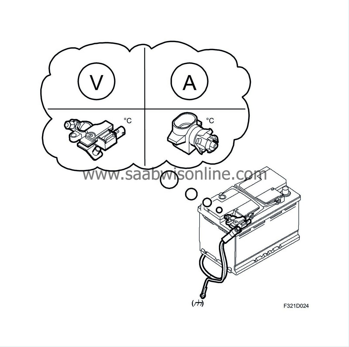
Battery current sensor
The battery charge level SOC (State of Charge) is calculated from the battery voltage when the battery has been at rest for several hours. When the car is next used, the SOC calculated from the rest voltage is taken as a starting point; this value is then corrected by the current (charge/discharge) through the battery.The battery current sensor (343) measures the amount of current and its direction to determine the level of current charging or discharging the battery. This value constitutes the basis for calculation of the battery charge level SOC (State of Charge) during operation. The battery state of charge is defined as the present capacity of the battery divided by its specified capacity. The capacity is measured in ampere-hours, Ah. When the car is produced, the battery capacity (Ah) is programmed into the battery current sensor. When the battery is changed, the new battery capacity must be programmed in again if its capacity deviates from the factory value.
The current is calculated by measuring the voltage drop over a current shunt built into the battery current sensor. To be able to calculate the SOC correctly, the battery voltage and battery temperature must be known. The battery current sensor measures the voltage and temperature. To achieve a correct battery temperature, the external temperature is used with a correction to the temperature measured by the battery current sensor, this information comes from BCM via the I-bus.

On the basis of the battery voltage, battery current, temperature and SOC, the optimum charge voltage is determined for each given situation. The battery should be charged optimally, neither too much nor too little, to ensure reduced fuel consumption, a high charge level and long battery life. If a situation arises where the alternator charge current is not sufficient to maintain the energy balance in the system (falling system voltage), BCM will request an increased idle to increase the alternator charging capacity. On the other hand, under certain circumstances when the battery SOC is high and the car's own consumption is low, the alternator may be shut down. This gives a fuel saving.
