Grinding of valve and seat, A20NFT/LHU
|
|
Grinding of valve and seat, A20NFT/LHU
|
|
Summary: measuring and renovation of valves
|
|
•
|
Correct valve servicing is crucial for engine performance. This means that all measurement procedures which are specified in detail must be followed in order to detect components which are outside the specification.
|
|
•
|
If the measurement procedures reveal that the valve or the valve seat must be renovated, it is very important to carry out measurement after renovation.
|
|
Method for measurement of the width of the valve seat
|
|
1.
|
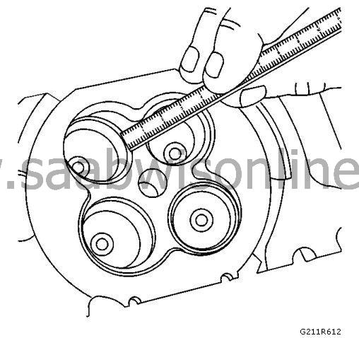
Measure the width of the valve seat in the top cover using a correct scale.
|
|
2.
|
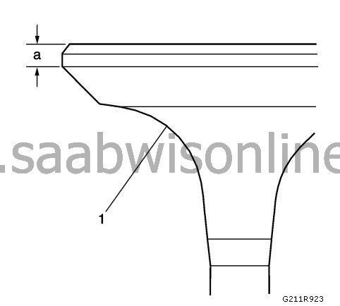
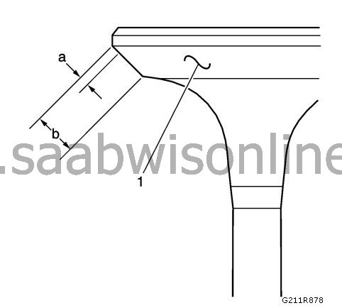
Measure the width of the seat (b) on the valve surface (1) using a correct measuring instrument.
|
|
3.
|
|
Note
|
|
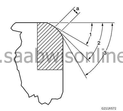
The contact surface of the seat must be at least 0.5 mm (0.020 in.) from the outer diameter, edge (a) on the valve. If the contact surface is too close too the edges, the seat must be renovated in order to move the contact surface away from the edge.
|
Compare your measurement results with the specifications available in
Engine's mechanical specifications (A20NFT/LHU)
.
|
|
4.
|
If the width of the seat is acceptable, check the roundness of the valve seat using the method for measurement of the roundness of valves.
|
|
5.
|
If the width of the seat is unacceptable, you must grind the valve seat using the method for renovation of valves and seats in order to return the width to the specification. Correct valve seat width is crucial to for correct dissipation of heat from the valve.
|
|
Method for measurement of the roundness of the valve seat
|
|
1.
|
Measure the roundness of the valve seat using a dial gauge secured to a conical guide pin mounted on the guide. The guide pin must have a specific binding when it is fitted to the guide.
|
|
2.
|
 Warning
|
|
The guide pin used must be of the correct size. Do not use adjustable guide pins. Adjustable guide pins may damage the valve guides.
|
|
|
|
|
|
Compare your measurement results with the specifications available in
Engine's mechanical specifications (A20NFT/LHU)
.
|
|
3.
|
If the valve seat exceeds the specification for roundness, the valve and the valve seat must be ground using the method for renovation of valves and seats.
|
|
4.
|
If new valves are used, the roundness of the valves must be within 0.05 mm (0.002 in.).
|
|
Measurement action for valve head outer diameter and chamfer
|
|
2.
|
If the outer diameter and chamfer of the valve head are within the specification, test the concentricity of the valve seat (1) using the measurement action for valve-to-seat concentricity. Check again the outer diameter and chamfer of the valve head once you have completed the concentricity measurement if the valve seat has been renovated.
|
|
Method for measurement of valve-to-seat concentricity
|
|
1.
|
|
Note
|
|
•
|
Checking valve-to-seat concentricity determines whether there is a proper seal between the valve and the seat.
|
|
•
|
You must measure the valve surface and the valve seat in order to ensure a correct valve seal.
|
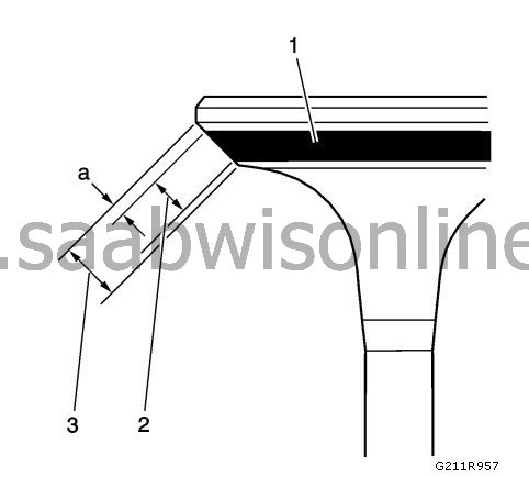
Lightly coat the valve surface (3) with blue paint (1).
|
|
2.
|
Fit the valve in the top cover.
|
|
3.
|
Rotate the valve towards the seat with sufficient pressure to wear off the paint.
|
|
4.
|
Remove the valve from the top cover.
|
|
5.
|
Check the contact surface of the valve.
|
|
|
•
|
If the surface of the valve is concentric and provides a sufficient seal against the valve stem, make a continuous mark (2) around the entire surface.
|
Note
|
|
The wear mark MUST be at least 0.5 mm (0.020 in.) from the outer diameter, edge (a) on the valve. If the wear mark is too close too the edge, the seat must be renovated in order to move the contact surface away from the edge.
|
|
Note
|
|
Do not grind or renovate the intake valve. If the intake valve is not compliant with the specification, replace the valve.
|
|
|
|
•
|
If the surface is not concentric with the stem, the mark will NOT be continuous around the surface of the valve. The valve must be reground or replaced and the seat must be renovated using the method for renovation of valves and seats.
|
|
Method for renovation of valves and seats
|
|
1.
|
|
Note
|
|
•
|
If the width, roundness or concentricity of the valve seat is outside the specifications, you must grind the seats in order to ensure correct heat dissipation and prevent the depositing of soot on the seats.
|
|
•
|
It is necessary to regrind the valve if renovation of the seat is required, unless a new valve is used.
|
Grind the valve sealing surface (a) to the correct angle specification (2) as listed in
Mechanical engine specifications (A20NFT/LHU)
.
|
|
3.
|
Grind the groove surface of the valve to the correct angle specification (3) as listed in
Mechanical engine specifications (A20NFT/LHU)
in order to reduce the width of the valve sealing surface (a) according to the specifications.
|
|
4.
|
|
Note
|
|
Do not grind or renovate the intake valve. If the intake valve seat has been renovated, replace the relevant intake valve.
|
Replace the intake valve if it does not meet the specification. Information can be found in
Mechanical engine specifications (A20NFT/LHU)
|
|
5.
|
If the original exhaust valve is used, grind the valve to the specifications as listed in
Mechanical engine specifications (A20NFT/LHU)
Measure the outer diameter and chamfer of the valve head again when you have ground it according to the measurement action for the outer diameter and chamfer of the valve head. Replace the exhaust valve unless it meets the specification. New valves do not need to be ground.
|
|
6.
|
When grinding valves and seats, you must grind off as little material as possible. Milled valve seats will lead to lowering of the valve spring pressure.
|
|
7.
|
Fit the valve in the top cover.
|
|
|
•
|
If you use reground exhaust valves, the valves must be fine-ground in the seats using a fine grinding paste. Work on regrinding and grinding in should provide smooth, even reground surfaces so that minimal fine grinding is required. Too much fine grinding will groove the valve surface and prevent a good seal being formed when the valve is hot.
|
|
|
•
|
Make sure that any residual fine grinding paste is removed from the valve and the seat using solvent and compressed air prior to final fitting.
|
|
8.
|
When the correct seat width has been achieved in the top cover, you must remeasure the height of the valve stem using the method for measurement of the height of the valve stem.
|
|
9.
|
If the height of the valve stem is acceptable, test the concentricity of the seats using the method for measurement of valve-to-seat concentricity.
|
|
Method for measurement of the height of the valve stem
|
|
1.
|
|
Note
|
|
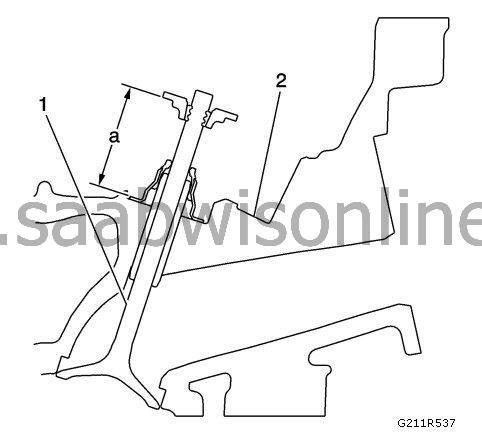
In order to establish the height of the valve stem, measure from the valve spring seat to the valve spring retainer.
|
Fit the valve (1) in the cylinder head valve guide (2).
|
|
2.
|
Make sure that the valve is seated properly in the valve seat of the top cover.
|
|
3.
|
Fit the valve stem's oil seal.
|
|
4.
|
Fit the valve spring retainer and the valve stem locks.
|
|
6.
|
If the maximum height specification is exceeded, a new valve must be fitted and the valve stem remeasured.
|
|
7.
|
|
Warning
|
|
Do NOT grind the tip of the valve stem. The tip of the valve is hardened, and the hardened surface is destroyed if it is ground, which will lead to premature wear and could cause engine damage.
|
|
|
|
|
|
|
Warning
|
|
DO NOT USE shims to adjust the valve stem height. Using shims will cause the valve spring to bottom out before the camshaft eccentric cam reaches its highest position, and this may result in engine damage.
|
|
|
|
|
|
If the valve stem still exceeds the maximum height specification, the top cover must be replaced.
|