Camshaft Position Actuator Replacement - Bank 2 (LF1 or LFW)
|
|
Camshaft Position Actuator Replacement - Bank 2 (LF1 or LFW)
|
Special Tools
EN-48313
Timing Chain Retention Tool
For equivalent regional tools, refer to
Special Tools
.
|
5.
|
|
Note
|
|
Rotate the crankshaft balancer bolt in a clockwise direction ONLY.
|
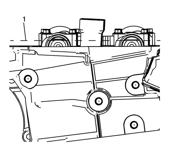
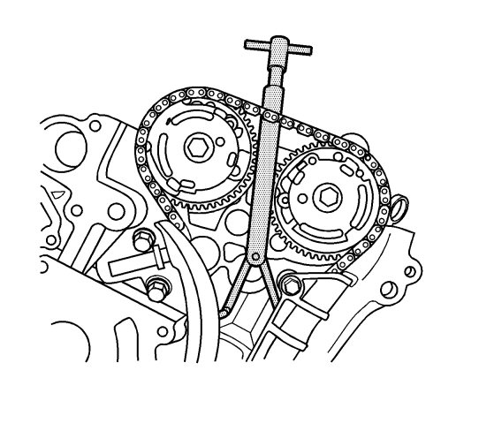
Rotate the crankshaft balancer using the balancer bolt until the camshafts are in a neutral (low tension) position. The camshafts will be parallel with the camshaft cover rail (1).
|
|
6.
|
|
Note
|
|
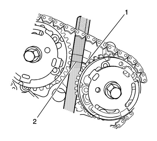
Ensure that the camshaft timing chain and the camshaft position actuators are marked for proper assembly.
|
Use a paint stick to create an alignment mark on one of the timing chain links (2) and the adjacent tooth on the exhaust camshaft position actuator (1).

|
|
7.
|
Use a paint stick to create an alignment mark on one of the timing chain links (3) and the adjacent tooth on the intake camshaft position actuator (4).
|
|
8.
|
Refer to
Torque Reaction Against Timing Drive Chain Caution
.
Use an open end wrench on the hex cast into the left intake and exhaust camshafts and rotate the camshafts toward each other in order to create slack in the chain between the actuators.
|
|
9.
|
Unscrew the
EN-48313
tool so that the legs of the tool are retracted.
|
|
10.
|
Insert the
EN-48313
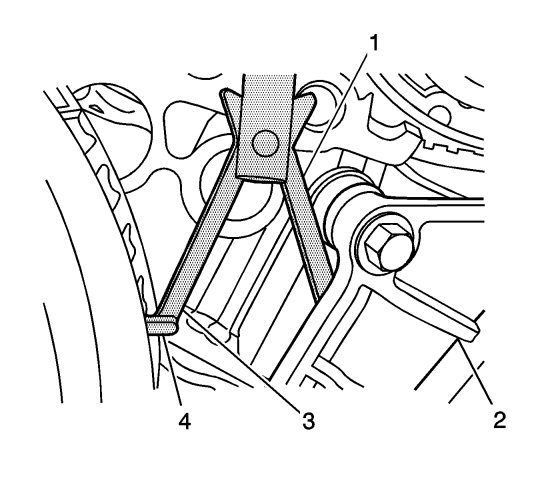
tool between the camshaft actuators, rearward of the timing chain until the bottom line that is scribed in the body of the tool (2) is adjacent to the top surface of the cylinder head (1). This is the approximate installed position.
|
|
11.
|
|
Note
|
|
The engine front cover is removed for clarity in the following graphics, but NOT required to perform the procedure.
|
Ensure that the feet (4) on the legs of the tool are facing the front of the engine.
|
|
12.
|
Partially expand the legs (1, 3) of the
EN-48313
tool by turning the T-shaped handle clockwise.
|
|
13.
|
Insert the leg of the tool (1) behind the timing chain guide (2).
|
|
14.
|
Continue expanding the
EN-48313
tool until the legs (1, 3) contact the timing chain. Do not tighten at this time.
|
|
15.
|
|
Note
|
|
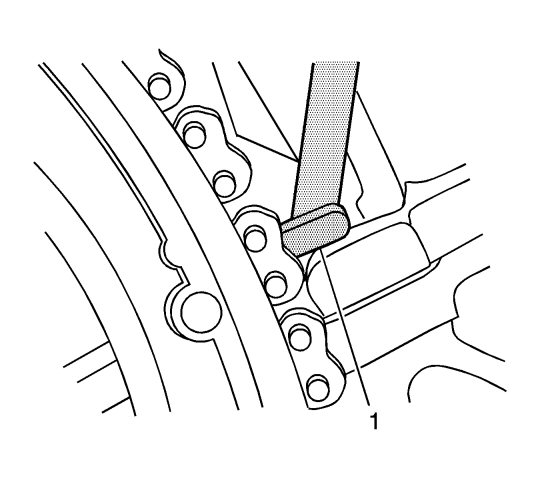
Ensure that the foot (1) of the
EN-48313
tool is engaged into one of the link pockets to prevent tool slippage during tightening of the
EN-48313
tool .
|
Hand tighten the
EN-48313
tool.
|
|
16.
|
Use an open end wrench on the hex cast into the left intake and exhaust camshafts and rotate the camshafts toward each other in order to create slack in the chain between the actuators.
|
|
17.
|
The
EN-48313
tool is now properly installed to hold the timing chain in position.
|
|
18.
|
Use an open end wrench on the hex cast into the camshaft in order to prevent engine rotation when loosening the camshaft position actuator bolt.
|
|
19.
|
If replacing the exhaust camshaft position actuator, then remove the bolt and the actuator.
|
|
20.
|
If replacing the intake camshaft position actuator, then remove the bolt and the actuator.
|
|
21.
|
If removing both the exhaust and intake camshaft actuators, the timing chain can be draped over the
EN-48313
tool once the actuators have been removed.
|
|
22.
|
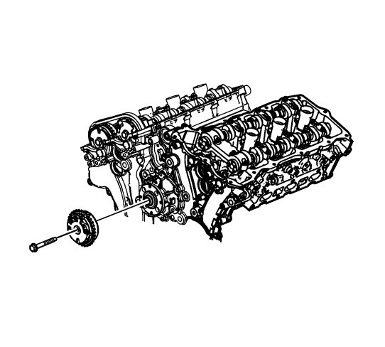
Rotate the actuator in order to align the opening in the actuator reluctor wheel with the cam sensor boss in the front cover, to allow actuator removal.
|
|
23.
|
Remove the camshaft thrust washer.
|
|
1.
|
|
Note
|
|
Ensure that the camshaft timing chain and the camshaft position actuators are marked for proper assembly.
|
Align the exhaust camshaft actuator alignment mark (1) to the timing chain alignment mark (2) made during disassembly.
|
|
2.
|
Ensure that the intake camshaft actuator alignment mark (4) and the timing chain alignment mark (3) also are aligned.
|
|
3.
|
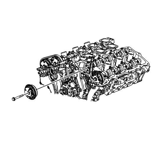
Position the exhaust camshaft actuator to the camshaft and install the actuator bolt hand tight.
|
|
4.
|
Remove the
EN-48313
tool .
|
|
5.
|
|
Note
|
|
•
|
The camshaft position actuator will vary depending on application.
|
|
•
|
Camshaft thrust washers must be installed on all 2010 applications when servicing the camshaft position actuators. Do not install washers on 2009 applications if they are not already present.
|
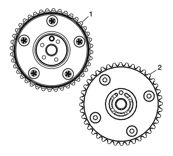
Ensure the proper camshaft thrust washer is used. Use a 1.6 mm (0.063 in) thrust washer on applications that have 5 attaching screws on the back side of the camshaft position actuator (1). Use a 1.1 mm (0.043 in) thick thrust washer with yellow speckles on applications that have 4 attaching screws on the back side of the camshaft position actuator (2).
|
|
6.
|
Install the thrust washer, if applicable.
|
|
7.
|
Refer to
Fastener Caution
.
If the exhaust camshaft position actuator has been replaced, then tighten the bolt to
58 Nm (43 lb ft)
.
|
|
8.
|
If the intake camshaft position actuator has been replaced, then tighten the bolt to
58 Nm (43 lb ft)
.
|
|
9.
|
If both the exhaust and intake has been replaced, then tighten bolt to
58 Nm (43 lb ft)
.
|