PRE-RELEASE
Intake Manifold Replacement
| Intake Manifold Replacement |
| Removal Procedure |
| 1. |
Remove the power steering fluid reservoir upper bracket only.
|
|
| 2. |
Remove the power brake booster vacuum check valve and hose. Refer to
Power Brake Booster Vacuum Check Valve and Hose Replacement (LF1)
Power Brake Booster Vacuum Check Valve and Hose Replacement (LAU)
.
|
|
| 3. |
Remove the coolant air bleed pipe. Refer to
Engine Coolant Air Bleed Pipe Replacement (LAU)
Engine Coolant Air Bleed Pipe Replacement (LF1)
.
|
|
| 4. |
Remove the intake manifold cover. Refer to
Intake Manifold Cover Replacement
.
|
|
| 5. |
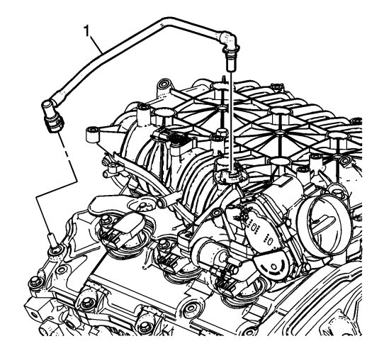
Disconnect and remove the positive crankcase ventilation (PCV) tube (1) from the intake manifold and right camshaft cover.
|
|
| 6. |
Remove the evaporative emission (EVAP) hose from the intake manifold and EVAP solenoid.
|
|
| 7. |
Remove the fuel pipe shield. Refer to
Fuel Pipe Shield Replacement
.
|
|
| 8. |
Unclip wire harnesses as necessary.
|
|
| 9. |
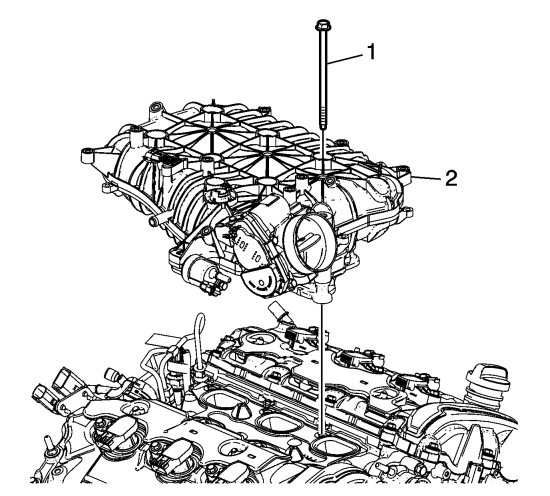
Remove the intake manifold bolts (1).
|
|
| 10. |
Remove the intake manifold assembly (2).
|
|
| 11. |
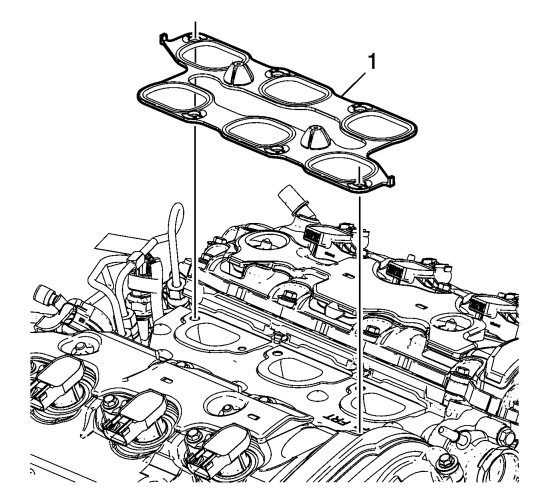
Remove and discard the intake manifold gasket (1).
|
|
| 12. |
To clean the intake manifold, refer to
Intake Manifold Cleaning and Inspection (LF1, LFW or LFX)
Intake Manifold Cleaning and Inspection (LAU or LBW)
.
|
|
| 13. |
To disassemble the intake manifold, refer to
Intake Manifold Disassemble (LF1, LFW or LFX)
Intake Manifold Disassemble (LAU or LBW)
.
|
|
| Installation Procedure |
| 1. |
Assemble the intake manifold if needed. Refer to
Intake Manifold Assemble (LF1, LFW or LFX)
Intake Manifold Assemble (LAU or LBW)
.
|
|
| 2. |
Install the NEW intake manifold gasket (1).
|
|
| 3. |
Install the intake manifold assembly (2).
|
|
| 4. |
Refer to
Fastener Caution
.
Install the intake manifold bolts (1). |
|
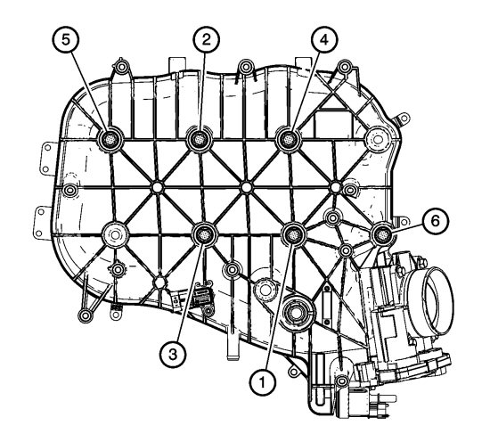
| 5. |
Tighten the intake manifold bolts in the sequence shown.
|
|
| 6. |
Tighten the intake manifold bolts in sequence to
23 Nm (17 lb ft)
.
|
|
| 7. |
Tighten the intake manifold bolts a second time in sequence to
23 Nm (17 lb ft)
.
|
|
| 8. |
Remove the fuel pipe shield. Refer to
Fuel Pipe Shield Replacement
.
|
|
| 9. |
Connect the EVAP hose to the upper intake manifold and EVAP solenoid.
|
|
| 10. |
Connect the PCV tube assembly (1) to the upper intake manifold and the right camshaft cover.
|
|
| 11. |
Install coolant hose.
|
|
| 12. |
Install intake manifold cover. Refer to
Intake Manifold Cover Replacement
.
|
|
| 13. |
Install the coolant air bleed pipe. Refer to
Engine Coolant Air Bleed Pipe Replacement (LAU)
Engine Coolant Air Bleed Pipe Replacement (LF1)
.
|
|
| 14. |
Install the power steering fluid reservoir upper bracket.
|
|
| 15. |
Install the power brake booster vacuum check valve and hose. Refer to
Power Brake Booster Vacuum Check Valve and Hose Replacement (LF1)
Power Brake Booster Vacuum Check Valve and Hose Replacement (LAU)
.
|
|
