PRE-RELEASE
Fuel Injector Replacement
| Fuel Injector Replacement |
Special Tools
| • |
EN-47909
Injector Bore and Sleeve Cleaning Kit
|
|
| • |
EN-48266
Injector Seal Installer and Sizer
|
|
| • |
GE-6125-1B
Slide Hammer
|
|
| • |
EN 3721-A
Injector Remover
|
|
| • |
EN 39313
Spark Plug Port Adapter
|
|
For equivalent regional tools, refer to Special Tools
| Removal Procedure |
| 1. |
Relieve the high side fuel system pressure. Refer to
Fuel Pressure Relief
.
|
|
| 2. |
Remove the fuel injection fuel rail assembly. Refer to Fuel Injection Fuel Rail Assembly Replacement - Bank 1 (LF1, LFW) or Fuel Injection Fuel Rail Assembly Replacement - Bank 2 (LF1, LFW) . |
|||||||
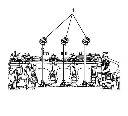
| 3. |
Remove and discard the three fuel injector retaining rings (1).
|
|
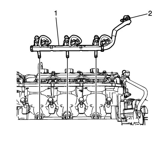
| 4. |
Remove the direct fuel injectors and harness (1) as an assembly, and disconnect the electrical connector (2). If necessary, use the
GE-6125-1B
slide hammer with the
EN 3721-A
injector remover in order to remove the direct fuel injectors evenly.
|
|
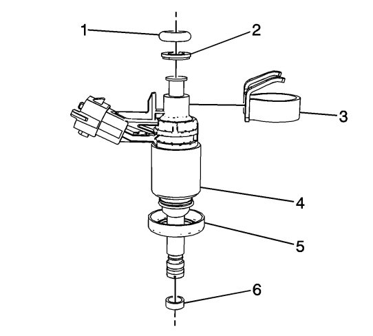
| 5. |
Remove and discard the following components from the fuel injectors (4).
|
|
| • |
Upper O-ring Seal (1)
|
| • |
Plastic Spacer (2)
|
| • |
Retaining Ring (3)
|
| • |
Isolator Cup (5)
|
| • |
Teflon Seal (6)
|
| 6. |
Inspect the fuel rail injector bores and clean with the
EN 39313
adapter, and
EN-47909
cleaning kit, if required.
|
|
| Installation Procedure |
| 1. |
Install the following NEW components to the fuel injectors. Use steps 2 through 8 to install these components.
|
|||||||
| • |
Upper O-ring Seal (1)
|
| • |
Plastic Spacer (2)
|
| • |
Retaining Ring (3)
|
| • |
Isolator Cup (5)
|
| • |
Teflon Seal (6)
|
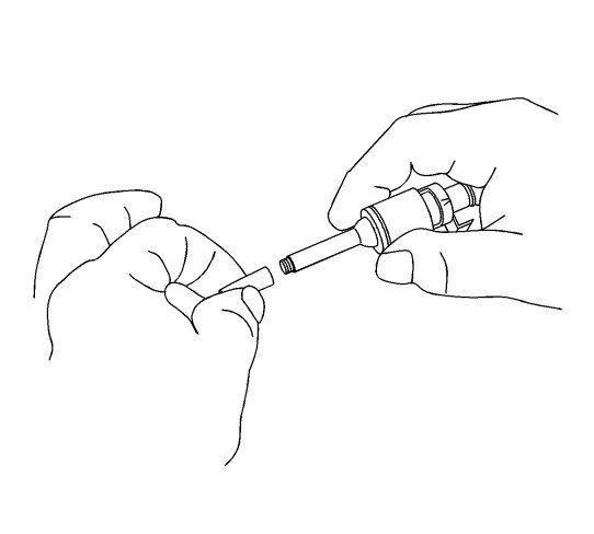
| 2. |
From the
EN-48266
installer, position the EN 48266-1 to the injector tip.
|
|
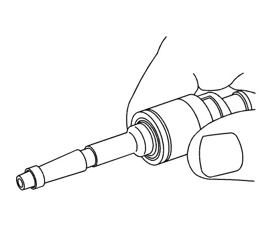
| 3. |
Install a NEW teflon seal onto the EN 48266-1. 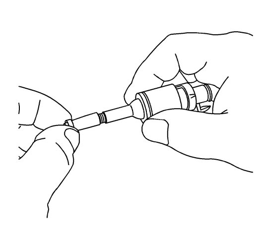
|
|||||||
| 4. |
Pull the NEW teflon seal by hand over the EN 48266-1 and into the groove in the injector.
|
|
| 5. |
Remove the EN 48266-1 from the injector tip.
|
|
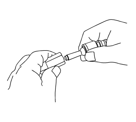
| 6. |
From the
EN-48266
installer, install the EN 48266-2 to the injector tip.
|
|
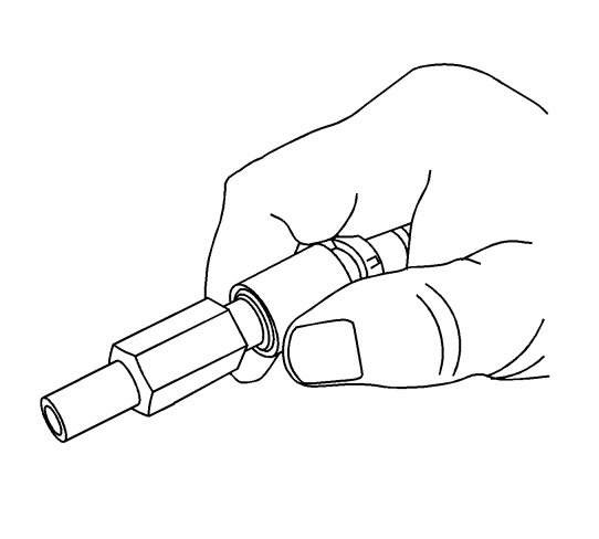
| 7. |
Using EN 48266-2, resize the teflon seal. Install the EN 48266-2, until it bottoms out against the injector body, and rotate the EN 48266-2 while applying only moderate force 180 degrees in one direction and then 180 degrees back in the other direction.
|
|
| 8. |
Remove the EN 48266-2.
|
|
| 9. |
Install the direct fuel injectors and harness (1) as an assembly and connect the electrical connector (2).
|
|
| 10. |
Install the fuel injection fuel rail assembly. Refer to Fuel Injection Fuel Rail Assembly Replacement - Bank 1 (LF1, LFW) or Fuel Injection Fuel Rail Assembly Replacement - Bank 2 (LF1, LFW) . |
|||||||
