PRE-RELEASE
Control Solenoid Valve and Transmission Control Module Assembly Replacement
| Control Solenoid Valve and Transmission Control Module Assembly Replacement |
| Removal Procedure |
| 1. |
Remove the control valve body cover. Refer to
Control Valve Body Cover Replacement
.
|
|
| 2. |
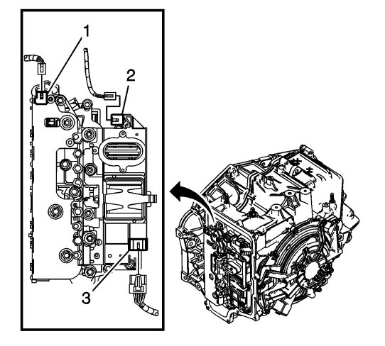
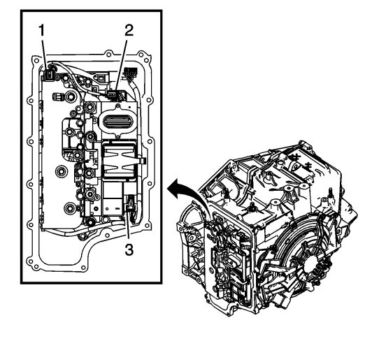
Disconnect the input speed sensor electrical connector (1).
|
|
| 3. |
Disconnect the output speed sensor electrical connector (2).
|
|
| 4. |
Disconnect the shift position switch electrical connector (3).
|
|
| 5. |
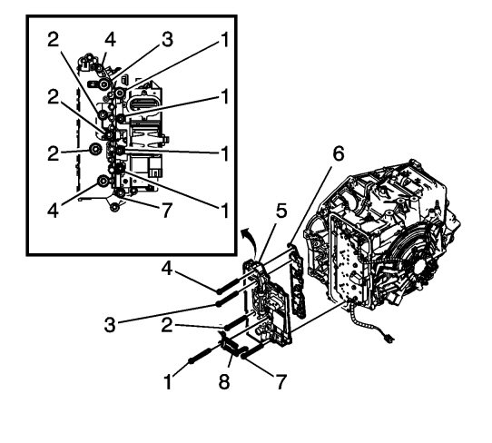
Remove the 4 control valve body bolts (1) M6 x 80.
|
|
| 6. |
Position the control solenoid valve spring (8) to the side. Spring will be released with the removal of the control valve body assembly.
|
|
| 7. |
Remove the 2 control valve body bolts (4) M6 x 65.
|
|
| 8. |
Remove the control valve body bolt (3) M6 x 42.
|
|
| 9. |
Remove the 3 control valve body bolts (2) M6 x 95.
|
|
| 10. |
Remove the control valve body bolt (7) M6 x 55.
|
|
| 11. |
Remove the control solenoid valve body and transmission control module (TCM) assembly (5).
|
|
| 12. |
Remove the control solenoid valve assembly filter plate (6). |
|||||||||
 Warning
| • |
Discard the filler plate. It is not reusable.
|
| • |
Inspect the pressure switch manifold seals for damage or contamination. Replace the control solenoid valve assembly as necessary.
|
| • |
Inspect the upper channel plate bolt holes for damage, peening or burnelling. Damage around the bolt holes near the pressure control switch's (PCS) feed holes may cause leakage around the PCS seals. Replace the upper channel plate if necessary.
|
| Installation Procedure |
| 1. |
Install a NEW control solenoid valve assembly filter plate (1). 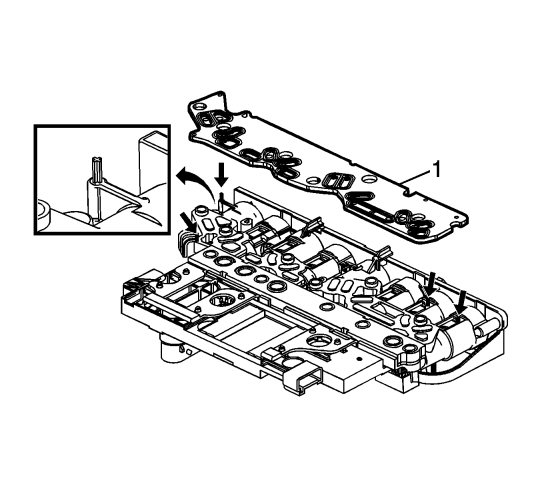
|
|||||||||
| 2. |
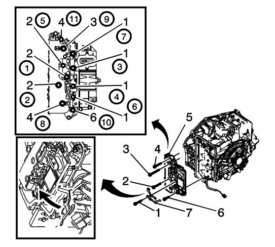
Install the control solenoid valve body and TCM assembly (5).
|
|
| 3. |
Rotate the control solenoid valve spring (7) into position.
|
|
| 4. |
Refer to
Fastener Caution
.
Install the 4 control valve body bolts (1) M6 x 80. |
|||||||
| 5. |
Install the control valve body bolt (6) M6 x 55.
|
|
| 6. |
Install the 3 control valve body bolts (2) M6 x 95.
|
|
| 7. |
Install the control valve body bolt (3) M6 x 42.
|
|
| 8. |
Install the 2 control valve body bolts (4) M6 x 65 and tighten to
12 Nm (106 lb in)
.
|
|
| 9. |
Connect the input speed sensor electrical connector (1).
|
|
| 10. |
Connect the output speed sensor electrical connector (2).
|
|
| 11. |
Connect the shift position switch electrical connector (3).
|
|
| 12. |
Install the control valve body cover. Refer to
Control Valve Body Cover Replacement
.
|
|
| 13. |
If a NEW TCM has been installed into the vehicle, the NEW module needs to be reprogrammed. Refer to
Service Programming System (SPS)
.
|
|
| 14. |
Reset the transmission's adaptive values. See Resetting of the transmission's adaption . |
||||||||||||||||||||||
