Control Valve Lower Body and Upper Body Replacement
|
|
Control Valve Lower Body and Upper Body Replacement
|
|
2.
|
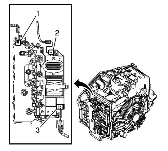
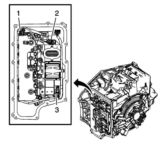
Disconnect the input speed sensor electrical connector (1).
|
|
3.
|
Disconnect the output speed sensor electrical connector (2).
|
|
4.
|
Disconnect the shift position switch electrical connector (3).
|
|
5.
|
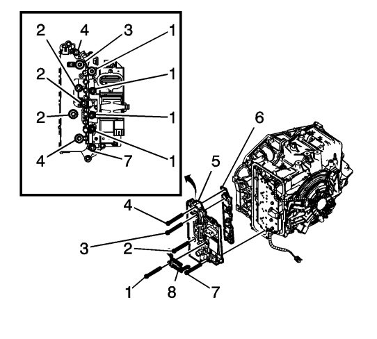
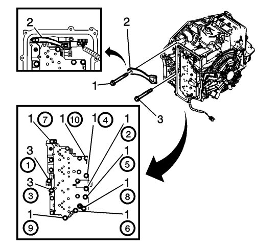
Remove the 4 control valve body bolts (1) M6 x 80.
|
|
6.
|
Position the control solenoid valve spring (8) to the side. Spring will be released with removal of lower control valve body.
|
|
7.
|
Remove the 2 control valve body bolts (4) M6 x 65.
|
|
8.
|
Remove the control valve body bolt (3) M6 x 42.
|
|
9.
|
Remove the 3 control valve body bolts (2) M6 x 95.
|
|
10.
|
Remove the control valve body bolt (7) M6 x 55.
|
|
11.
|
Remove the control solenoid valve body and transmission control module (TCM) assembly (5).
|
|
12.
|
 Warning
|
|
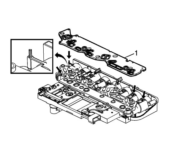
Use care when removing or installing the filter plate assembly. A broken or missing retaining tab may not adequately secure the filter plate to the control solenoid valve assembly, resulting in possible damage or contamination.
|
|
|
|
|
|
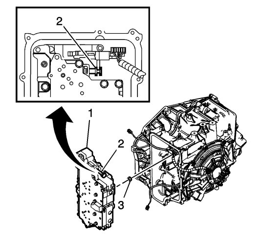
Remove the control solenoid valve body assembly filter plate (6).
|
|
|
•
|
Discard the filler plate. It is not reusable.
|
|
|
•
|
Inspect the pressure switch manifold seals for damage or contamination. Replace the control solenoid valve assembly as necessary.
|
|
|
•
|
Inspect the upper channel plate bolt holes for damage, peening or burnelling. Damage around the bolt holes near the PCS switch's feed holes may cause leakage around the PCS switch seals. Replace the upper channel plate if necessary.
|
|
13.
|
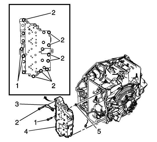
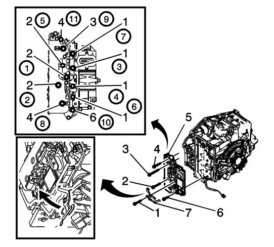
Remove the 8 control valve body bolts (2) M6 x 65.
|
|
14.
|
Remove the 2 control valve body bolts (1) M6 x 55.
|
|
15.
|
Remove the manual shaft detent assembly (3).
|
|
16.
|
Remove the control valve body assembly (4).
|
|
17.
|
The control solenoid valve spring can now be fully removed from the lower control valve body assembly.
|
|
18.
|
|
Note
|
|
The clutch fluid passage seal is not reusable.
|
Remove the 1-2-3-4 clutch fluid passage seal (5).
|
|
1.
|
|
Note
|
|
The clutch fluid passage seal is not reusable.
|
Install a NEW 1-2-3-4 clutch fluid passage seal (3).
|
|
2.
|
|
Note
|
|
Ensure the control solenoid valve spring is attached to the lower control valve body assembly.
|
|
Note
|
|
Align the manual valve (2) to the detent lever assembly while installing the lower control valve body assembly.
|
Install the control valve body assembly (1).
|
|
3.
|
|
Note
|
|
Ensure proper alignment of the detent assembly to the detent lever assembly with position switch while tightening the bolt. The detent assembly can move and hit the valve body assembly that could cause improper engagement with the detent lever assembly.
|
Install the manual shaft detent assembly (2).
|
|
4.
|
Refer to
Fastener Caution
.
|
Note
|
|
Install all bolts before tightening, then tighten in specified sequence.
|
Install the 8 control valve body bolts (1) M6 x 65 and tighten to
12 Nm (106 lb in)
.
|
|
5.
|
Install the 2 control valve body bolts (3) M6 x 55 and tighten to
12 Nm (106 lb in)
.
|
|
6.
|
|
Warning
|
|
Use care when removing or installing the filter plate assembly. A broken or missing retaining tab may not adequately secure the filter plate to the control solenoid valve assembly, resulting in possible damage or contamination.
|
|
|
|
|
|
Install a NEW control solenoid valve assembly filter plate (1).
|
|
7.
|
Install the control solenoid valve body and TCM assembly (5).
|
|
8.
|
Rotate the control solenoid valve spring (7) into position.
|
|
9.
|
|
Note
|
|
Install all bolts before tightening, then tighten in specified sequence.
|
Install the 4 control valve body bolts (1) M6 x 80.
|
|
10.
|
Install the control valve body bolt (6) M6 x 55.
|
|
11.
|
Install the 3 control valve body bolts (2) M6 x 95.
|
|
12.
|
Install the control valve body bolt (3) M6 x 42.
|
|
13.
|
Install the 2 control valve body bolts (4) M6 x 65.
|
|
14.
|
Connect the input speed sensor electrical connector (1).
|
|
15.
|
Connect the output speed sensor electrical connector (2).
|
|
16.
|
Connect the shift position switch electrical connector (3).
|
|
19.
|
|
Note
|
|
After an internal transmission repair or replacement of internal parts, the transmission's adaption must be reset.
|
Perform resetting of the transmission's adaption. See
Resetting of the transmission's adaption
.
|
