Steering Linkage Inner Tie Rod Inspection
|
|
Steering Linkage Inner Tie Rod Inspection
|
Special Tools
GE 8001
Dial Indicator Set
For equivalent regional tools, refer to
Special Tools
.
|
1.
|
|
Note
|
|
This inspection procedure does not supersede local government required inspections that have more stringent requirements.
|
Turn the ignition key to the ON position with the engine OFF.
|
|
2.
|
With the aid of an assistant, turn the steering wheel to the full stop position and hold the steering wheel in that position until the test is complete. The tie rod being tested should be inside the steering gear housing seated against the steering stop.
|
|
4.
|
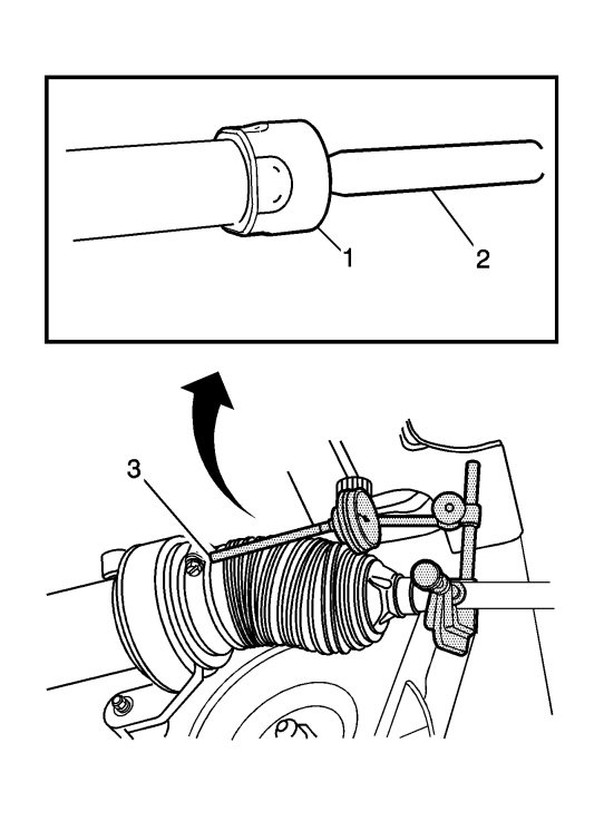
If there is not a good location for the
GE-8001
dial indicator pointer at the steering gear housing, install a large worm gear hose clamp to the steering gear housing over the larger steering gear boot clamp and align the clamp so that the screw can be a location for the
GE-8001
dial indicator pointer.
|
|
5.
|
Install the
GE-8001
dial indicator between the inner tie rod (2) and the steering gear housing or the worm gear clamp in such a way as to measure the lash between the inner tie rod and the steering gear housing.
|
|
6.
|
|
Note
|
|
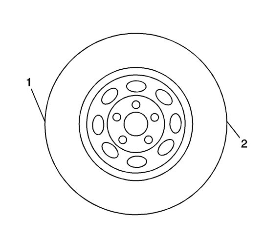
Only move the tire enough to feel any lash between the inner tie rod and the inner tie rod housing without moving the steering gear rack.
|
Grasping the tire at the 3 o'clock (2) and 9 o'clock (1) positions, gently push in on one side of the tire in order to remove any lash.
|
|
7.
|
Zero the
GE-8001
dial indicator.
|
|
8.
|
On the same side of the tire previously pushed in, gently pull out and measure the lash.
|
|
9.
|
Record the measurement shown on the
GE-8001
dial indicator.
|
|
11.
|
Repeat the procedure for the other side.
|
