PRE-RELEASE
Front Hinge Pillar Body Sectioning
| Front Hinge Pillar Body Sectioning |
| Removal Procedure |
| 1. |
Refer to
Approved Equipment for Collision Repair Warning
See Warning during the repair of collision damage with repair sheet metal Refer to Glass and Sheet Metal Handling Warning
Disable the supplemental inflatable restraint (SIR) system. Refer to SIR Disabling and Enabling . |
|||||||
| 2. |
Disconnect the negative battery cable. Refer to
Battery Negative Cable Disconnection and Connection
.
|
|
| 3. |
Remove all related panels and components.
|
|
| 4. |
Repair as much of the damage as possible to factory specifications. Refer to
Dimensions - Body
.
|
|
| 5. |
Note the position of the seals and anti-corrosive materials in the repair area and remove them if necessary.
|
|
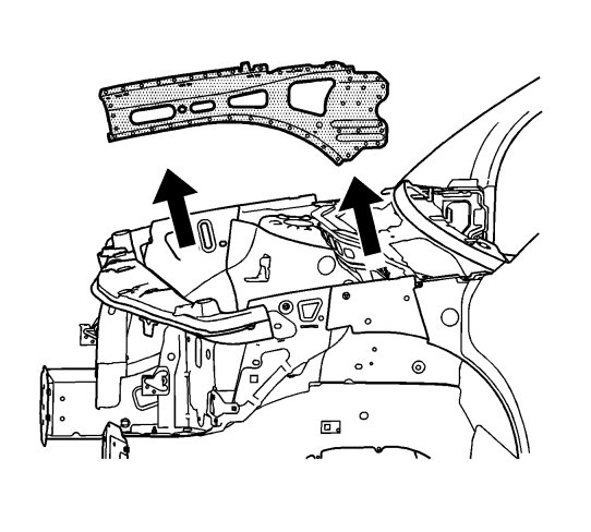
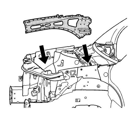
| 6. |
Drill spot welds and remove the front upper outer rail.
|
|
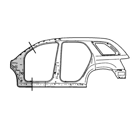
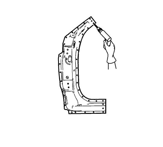
| 7. |
Cut the panel where sectioning is to be performed. 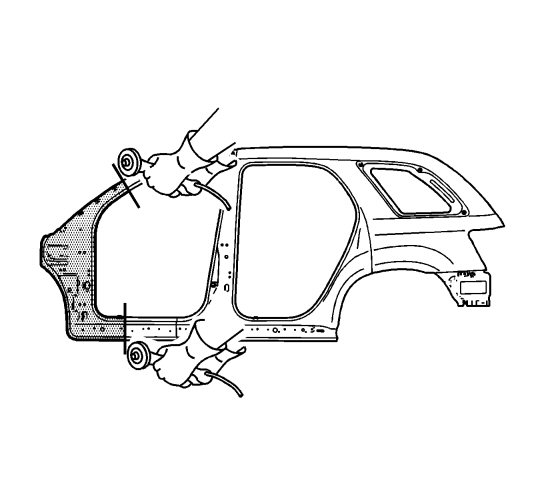
|
|||||||
| 8. |
Perform any additional sheet metal sectioning work depending on the nature of the character. See:
|
|
| 9. |
Locate and drill out all factory welds. Note the number and location of the welds for installations of the service part.
|
|
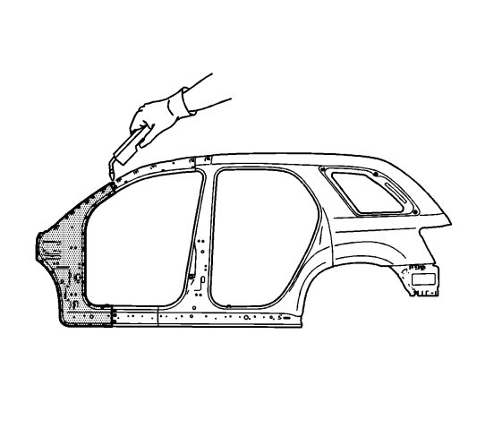
| 10. |
Remove the damaged windshield pillar section.
|
|
| Installation Procedure |
| 1. |
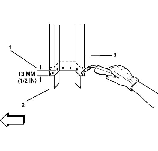
Cut out the panel from the service part (1) to overlap the original panel with 25 mm (1 inch) at the joining points.
|
|
| 2. |
Drill 8 mm (5/16 in) plug weld holes in the service part as necessary in the locations noted from the original panel and along the sectioning cut.
|
|||||||
| 3. |
Prepare all mating surfaces, as necessary.
|
|
| 4. |
Apply GM-approved Weld-Thru Coating or equivalent to all mating surfaces. Refer to
Anti-Corrosion Treatment and Repair
.
|
|
| 5. |
Fit the backing plate (2) halfway into the sectioning joint, clamp and plug weld to the vehicle.
|
|
| 6. |
Position the service part.
|
|
| 7. |
Plug weld accordingly.
|
|
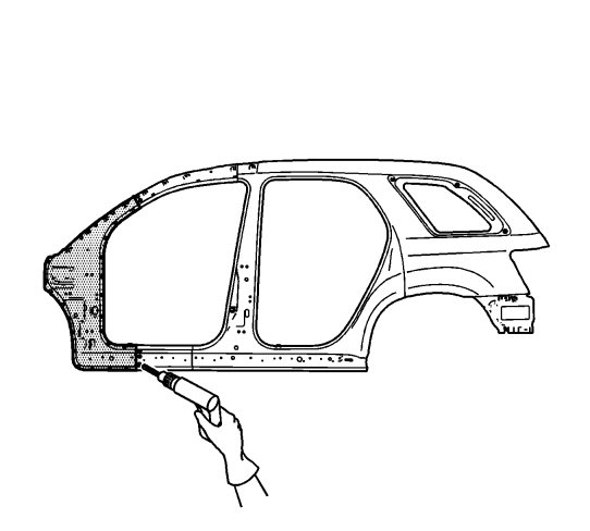
| 8. |
Stitch weld the sectioning joint. |
|||||||
| 9. |
Clean and prepare all welded surfaces.
|
|
| 10. |
Install the front upper outer rail.
|
|
| 11. |
Apply the sealers and anti-corrosion materials to the repair area, as necessary. Refer to
Anti-Corrosion Treatment and Repair
.
|
|
| 12. |
Paint the repair area. Refer to
Basecoat/Clearcoat Paint Systems
.
|
|
| 13. |
Install all related panels and components.
|
|
| 14. |
Connect the negative battery cable. Refer to
Battery Negative Cable Disconnection and Connection
.
|
|
| 15. |
Activate the SIR system. Refer to
SIR Disabling and Enabling
.
|
|
